A Soft Processor MicroBlaze-Based Embedded
System for Cardiac Monitoring
El Hassan El Mimouni
University Sidi Mohammed Ben Abdellah Fès, Morocco
Mohammed Karim
University Sidi Mohammed Ben Abdellah Fès, Morocco
Abstract—this paper aims to contribute to the efforts of design community to demonstrate the effectiveness of the state of the art Field Programmable Gate Array (FPGA), in the embedded systems development, taking a case study in the biomedical field. With this design approach, we have developed a System on Chip (SoC) for cardiac monitoring based on the soft processor MicroBlaze and the Xilkernel Real Time Operating System (RTOS), both from Xilinx. The system permits the acquisition and the digitizing of the Electrocardiogram (ECG) analog signal, displaying heart rate on seven segments module and ECG on Video Graphics Adapter (VGA) screen, tracing the heart rate variability (HRV) tachogram, and communication with a Personal Computer (PC) via the serial port. We have used the MIT_BIH Database records to test and evaluate our implementation performance. In terms of the resources utilization, the implementation occupies around 70% of the used FPGA, namely the Xilinx Spartan 6 XC6SLX16. The accuracy of the QRS detection exceeds 96%.
Keywords—ECG; FPGA; Heart Rate Variability; MicroBlaze; QRS detection; SoC; Xilkernel
I. INTRODUCTION
A Field Programmable Gate Array (FPGA) is a high density Programmable Logic Device (PLD) that allows high performance data processing. Its digital signal processing (DSP) performance is derived from the ability to construct naturally parallel structures or modules, achieving a hardware multitasking. This rapid increase of complexity emerged also the new concept of SoC that integrates most of the functions of the end product into a single chip; this is encouraged by the reuse of optimized Intellectual Properties (IPs), particularly soft and hard processors; in fact, FPGAs are nowadays so dense that it is possible to embed a processor (soft or hard) on the single chip and there is still enough room for eventual additional functionalities. Moreover, these FPGAs come with sophisticated software tools for the processor, like C/C++ compilers and a RTOS kernel; this improves the design abstraction and consequently the productivity [1 - 4].
The electrocardiogram signal (ECG) is one of the most commonly used in medical practice thanks to its non-invasive nature, simple acquisition process and the meaningful information it contains; the analysis of such information permits to evaluate the state of the heart. Thus, the cardiac monitoring by means the ECG is a standard practice in intensive care, emergency rooms, ambulatory monitoring, etc. It is worth noting that the cardiac rhythm monitoring by means the heart rate variability (HRV), increasingly studied in the
recent years, and has become also an important way to assert the heart’s condition [5 - 9].
II. SYSTEM OVERVIEW
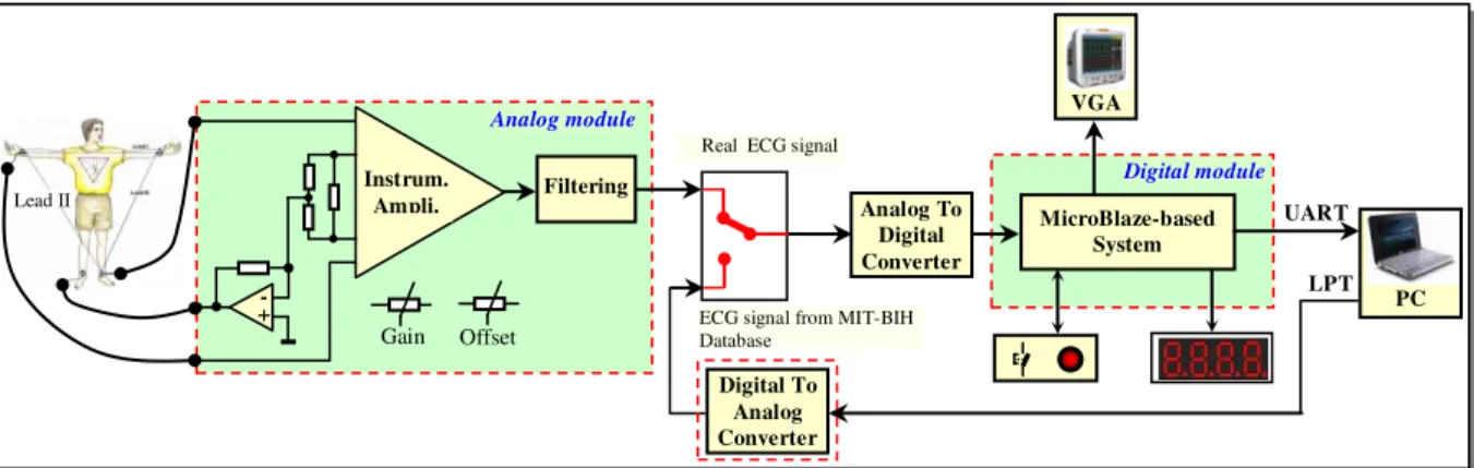
We have designed and implemented a prototype of basic embedded system for cardiac monitoring, whose functional block diagram is shown in the figure 2; it exhibits a modular structure that facilitates the development and debugging. Thus, it includes 2 main modules:
An analog module intended for acquiring and conditioning of the analog ECG signal to make it appropriate for use by the second digital module ; A soft processor-based module digitizes and processes
the ECG signal.
A secondary module acts as a way to facilitate testing system with the standard ECG records contained in the standard MIT-BIH database [10].
This implementation is to be considered as a strong improvement and a migrating to advanced new technology, mentioned above, of one of our previous works [11]; it can also be seen as a contribution to developing a more efficient and low-cost biomedical instrumentation.
ECG signal is the measure, via electrodes acquiring the voltage (potential difference) on the body surface, generated by the heart's electrical activity. As illustrated by the figure 1, the ECG is characterized mainly by 5 waves reflecting the activity of the heart during a cardiac cycle (R-R interval); these waves are called P, Q, R, S and T; the Q, R, and S waves are treated as a single composite wave known as the QRS complex. The ECG signal is typically characterized by maximum amplitude of 1 mV and a bandwidth of 0.05 Hz to 100 Hz [9, 12].
Fig. 2. System functional diagram block.
III. ANALOG MODULE
We used the Lead II that is the most commonly used lead for ECG ambulatory monitoring, because it’s a relative high -voltage deflection resulting in P, R and T waves. The reference electrode is connected to the right leg via an amplifier to reduce common mode noise, a principle commonly termed by “Right Leg Drive”. The two other electrodes, representing Lead II, attack an instrumentation amplifier (IA) we have achieved with off the shelf operational amplifiers, which present good performances, especially a relative good common mode rejection ratio (CMRR). The different types of noise are reduced by means analog filtering: low pass and anti-aliasing filter of 0-70 Hz,and notch filter for reducing noise effect of 50 Hz of AC power line. Finally, the output signal gain and offset of this stage are properly adapted to the analog to digital converter (ADC) of the digital module.
IV. SOFT PROCESSOR-BASED DIGITAL MODULE
Today’s FPGAs integrate existing IP cores achieving functionalities commonly used in the embedded systems world (GPIO, Timers, UART, SPI, VGA, etc.); they can be easily instantiated into a top-level design. Among them, the most important are the soft processors cores; indeed, the availability of such embedded subsystems in FPGAs opens a whole new world of possibilities. A soft or virtual processor is built by combining blocks of optimized HDL code inside an FPGA. In our case, it was the MicroBlaze, which is a reduced instruction set computer (RISC) optimized for implementation in Xilinx FPGAs [13].
The development of this module was guided by the Hardware/Software co-design techniques, which try to exploit the synergy of Hardware and Software with the goal to optimize and satisfy design constraints of a final product [14]. Thus, as development tool, we have used the XilinxEmbedded Development Kit (EDK), which is a suite of tools and Intellectual Property (IP) that permits the design of a complete embedded processor system for implementation in a Xilinx FPGAs [15]. We mention in particular:
The Xilinx Platform Studio (XPS) that is the development environment used for designing the hardwareaspect of an embedded processor system.
The Software Development Kit (SDK) that is an integrated development environment, complementary to XPS used for C/C++ embedded software application creation and verification.
As development board, we have used the Nexys 3 of Digilent that features Xilinx's Spartan-6 XC6SLX16 FPGA, 48 Mbytes of external memory, and enough I/O devices and ports to host a wide variety of digital systems [16].
A. Hardware
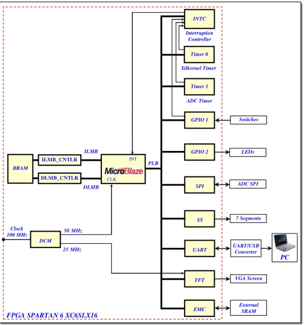
The foundation of the hardware of the design is created using the Base System Builder (BSB) wizard within XPS. This allows the use of pre-developed IPs cores with a series of Buses and Interfaces to connect the various hardware elements of the design. The figure 3 shows the architecture of our implementation; the design consists of the main following IPs cores:
MicroBlaze soft processor is the main and central element of the entire architecture; in other words, it represents the central and processing unit (CPU) of the system.
The Digital Clock Manager (DCM) primitive in FPGA provides advanced clocking capabilities; it optionally multiply or divide the incoming clock frequency to synthesize a new clock frequency.
Bus Local memory Bus (LMB) provides single-cycle access to on-chip RAM.
On-chip dual-port block RAM (BRAM) stores processor’s program instructions and data; as the application program exceeds the BRAM limit (32 Kbytes), the external SRAM is used for this purpose.
The Processor Local Bus (PLB) provides a connection to both on-and off-chip peripherals and memory. Timer 0 is required by Xilkernel RTOS to tick its
kernel.
Timer 1 is used to generate an interrupt every 5 ms (200 Hz) for ECG analog signal sampling, according to the Shannon theorem.
MicroBlaze-based System VGA
PC UART
LPT
Real ECG signal
Digital To Analog Converter
Analog To Digital Converter
ECG signal from MIT-BIH Database
Digital module
Instrum.
Ampli. Filtering
+ -
Gain Offset
Lead II
Fig. 3. MicroBlaze-based hardware.
General Purpose Input Output (GPIO) is used to communicate with simple human machine interface (HMI) that consists of switches and LEDs.
INTC is an interrupt controller used to concentrate multiple interrupt inputs from peripheral devices to a single interrupt output driving the unique processor interrupt input; hence, in this application, it captures kernel tick interrupt, 5 ms interrupt and so on.
SPI (Serial Peripheral Interface) is the IP core providing a serial interface to the small board PmodAD1 from Digilent, which features ADCS7476 that is an SPI ADC serving for ECG analog signal digitizing.
UART (Universal asynchronous Receiver Transmitter) is the IP core allowing serial communication with a PC (COM port), via an UART/USB converter, that is the FT232RQ; indeed, there is no COM port in the most modern PCs.
SS is a customized IP from Digilent; it controls the seven segments with time multiplexing, intended to heart rate display; that is a good example for Hardware/Software co-design illustration; in fact, this task could have been achieved by a certain C code function executed by the CPU; this customized IP offloads then the processor.
TFT (Thin Film Transistor) is the IP serving as interface for 18-bit VGA; it supports 25 MHz clock, generated from DCM, for display resolution of 640x480 pixels at 60 Hz refresh rate.
EMC (External Memory Controller) is the interface for on-board SRAM, which contains the application program and the video memory for VGA display.
B. Software
As the complexity of the embedded systems increases, the development in an RTOS environment is essential; it becomes ILM
CL
ILMB_CNTLR
BRAM
DLMB_CNTLR
INT
DLMB
SS PLB
Clock 100 MHz
Switches
FPGA SPARTAN 6 XC6SLX16
DCM
50MHz
25MHz UART
PC
SPI
UART/USB Converter Interruption
Controller INTC
CLK
ILMB LEDs
ADC SPI
7 Segments
VGA Screen
External SRAM Xilkernel Timer
ADC Timer
Timer 0
Timer 1
GPIO 1
GPIO 2
tools available in the new computer aided development (CAD) tools, like EDK. Thus, an application is broken into small pieces (tasks or threads) more easy to manage; each task deals with certain aspect of the application. In our case, the RTOS was Xilkernel from Xilinx. Xilkernel is a small, light-weight easy to use, robust and modular kernel. It provides features like scheduling, threads, inter-process communication (IPC) and synchronization, with a POSIX subset interface. It is integrated with EDK, easy to configure and free software [17].
Thus, the software application consists of Xilkernel threads executing on top of the kernel. In the following text of this section, we describe the RTOS structure of our software written in C language and in a bit more detail the QRS detection algorithm.
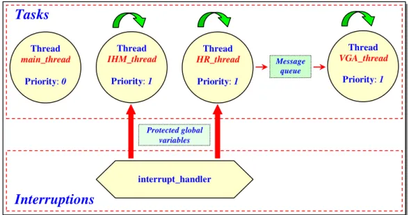
1) Software Structure
The figure 4 illustrates the software structure of the application in the Xilkernel RTOS context. We have configured Xilkernel to have round robin scheduling. Once Xilkernel is called and initialized, it calls its scheduler to manage the different application tasks:
The first task to run is the “main_thread”; it has the highest priority (0) and therefore always runs before any other tasks; this task creates the others threads and achieves necessary initializations and exits.
“IHM_thread” is the task where the state of a switch is read permitting the choice between acquisition of ECG or reading a small sequence of ECG signal stored in an array for testing purposes; A LED (LD0 in the board) blinks at measured cardiac rhythm.
“HR_thread” is the task responsible for calculating the heart rate for 10 s with an interpolation over 1 mn. “VGA_thread” deals with the display of the ECG in
VGA screen with a resolution of 640 x 480.
“interrupt_handler” is the interrupt service routine (ISR) that can be considered as a thread of high priority; that is the Timer 1 interrupt allowing processing critical events, like real-time acquiring of ECG, QRS detection and so on.
We have used as means of communication between threads: Protected global variables, so that there is no conflict in
access to these variables.
Message queue, an available technique in Xilkernel.
2) QRS Detection
The QRS complex of the ECG signal is the reference point for the most ECG applications. In this paper we adapted the algorithm subject of our previous work [18], in the MicroBlaze context. This detector uses a modified Pan and Tompkins algorithm [19], which is the most widely used and highly acknowledged algorithm, for its real-time aspect, robustness and efficiency; its structure with 2 stages is shared by many algorithms in the recent years:
The pre-processing stage has for purpose enhancing QRS complex with noise suppressing and artifacts. The decision stage determines the QRS candidates,
based on thresholding technique and a set of rules; this detection provides a logic signal (QRS flag).
Fig. 4. Application RTOS structure.
Tasks
Thread
main_thread
Priority: 0
Interruptions
Message queue
interrupt_handler
Protected global variables
Thread
IHM_thread
Priority: 1
Thread
HR_thread
Priority: 1
Thread
VGA_thread
V. EVALUATION
As described above, the system is implemented in reconfigurable circuit, that is, FPGA representing the strong actual trend for embedded systems designing. Our system is developed in the Xilinx EDK suite that enables design a complete embedded processor system for implementation in a Xilinx FPGA device. This evaluation focuses on the resources estimation and the QRS detection accuracy:
Based on the same tests realized in our previous work [18], the total accuracy of the QRS Detector exceeds 96%.
The implementation occupies around 70% of the used FPGA device, namely the Xilinx Spartan 6 XC6SLX16, which is the core of the development board, Nexys 3 of Digilent.
For testing our work, an excerpt of a MIT-BIH record, with 10000 samples (50 s), is saved in a text file, read from a simple Visual Basic application and presented to Nexys 3 board, via the parallel port, i.e. LPT1 of a PC, driving a simple digital to analog converter (DAC), provided by an R-2R resistor ladder network, at the sampling period mentioned above (5 ms). By convenience, the data is quantized with 8 bits. The figure 5 shows such an experimental setup. On another hand, the PC, via USB port emulating an UART link, receives from the Nexys 3 board the QRS flag and the HRV signals.
Fig. 5. The Design test via LPT1of a PC
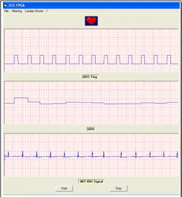
The figure 6 illustrates the global result of the experience with a screenshot, showing the ECG signal sent to the board (bottom signal), the QRS flag received from the board (top signal) and the HRV tachogram (middle signal).
The figure 7 presents a captured photo of the implementation running the program, with HR equal to 66 bpm (beats per minute) and a blinking LED (LD0 in the board) at measured cardiac rhythm.
The figure 8 illustrates the display result on VGA screen; it presents some resolution problems; it seems that the resolution doesn’t exceed (640x100); we think that this problem is related to some dysfunction in TFT IP core; we are trying to find the responsible bug.
Fig. 6. Screenshot of the test with LPT1 of a PC.
Fig. 7. Photo of the design with running program.
Fig. 8. ECG display on VGA screen.
GND
Nexys 3 UART via FT232RQ
Nexys 3 Board
Nexys 3 connector JA
LPT1 8
ECG raw Digital to
Analog Converter
PmodAD1 SCLK
MOSI
USB
D+ D-
PC
VI. CONCLUSIONS
We have designed and implemented a soft processor MicroBlaze-based embedded system for cardiac monitoring; it implements the most popular algorithm and widely adopted by the patient monitoring industry, that is, the Pan and Tompkins QRS detector algorithm, which is based on slope, amplitude and width information. It was developed with EDK suite tools with C code and in the Xilkernel RTOS environment. The accuracy of the QRS detection exceeds 96%. In terms of the resources utilization, our implementation occupies around 70% of the used FPGA, namely the Xilinx Spartan 6 XC6SLX16. Thus, there is still space for additional functionalities. The Hardware/Software co-design and RTOS were compatible with the parallelism natively permitted by the FPGA; so, the implementation parts are operated in parallel and executed concurrently, making possible a real-time and multitask processing.
Based on this successful basic implementation, the ongoing work has for purpose to try optimization and implementing more functionalities in such low cost FPGA devices, particularly an algorithm for myocardial Ischemia detection; there is also plan to use multiprocessor design, if needed, for more determinism, which satisfies the real-time constraints.
REFERENCES
[1] J. O. Hamblen, T. S. Hall, and M. D. Furman, Rapid Prototyping of Digital Systems, SOPC edition, Springer, 2008.
[2] Zainalabedin Navabi, Digital Design and Implementation with Field Programmable Devices, Springer, 2005.
[3] Xilinx System Generator for DSP V12.2, User Guide , July 2010.
[4] J. cong, B. Liu, J. Noguera, K. Vissers, and Z. Zhang, “High-level
synthesis for FPGAs: from prototyping to deployment,” in IEEE Transactions on computer-aided design of integrated circuits and systems, Vol. 30, No 4, April 2011.
[5] D. I. Fotiadis, A. Likas, L. Michalis and C. Papaloukas,
“Electrocardiogram (ECG): Automated Diagnosis”, Wiley encyclopedia
of biomedical engineering,” Vol. 2, pp. 1259-1275, ISBN 978-0-471-24967-2 (set), Wiley, 2006.
[6] L. Sörnmo and P. Laguna, Bioelectrical SignalProcessing in Cardiac and Neurological Applications, Elsevier (Academic Press), 2005.
[7] L. Sörnmo and P. Laguna, “Electrocardiogram (ECG) Signal Processing”, Wiley encyclopedia of biomedical engineering,” Vol. 2, pp. 1298-1313, ISBN 978-0-471-24967-2 (set), Wiley, 2006.
[8] W. J. Tompkins, Biomedical Digital SignalProcessing: C-Language Examples and Laboratory Experiments for the IBM PC, Englewood Cliffs, NJ: Prentice-Hall, 1993.
[9] Rajendra Acharya U, A.E. Spaan, Jasjit Suri, and Shankar M. Krishnan, Advances in Cardiac Signal Processing, Springer, 2007.
[10] http://www.physionet.org/cgi-bin/atm/ATM.
[11] E. El Mimouni, and M. Karim, “Design and implementation of an
embedded system for ambulatory cardiac monitoring,” in Journal of Telecommunications and Information Technology (JTIT), issue n°1 p. 23-32, Mars 2011.
[12] J. G. Webster, Medical Instrumentation Application and Design, Wiley, 2010.
[13] http://www.xilinx.com/support/documentation/sw_manuals/mb_ref_guid e.pdf.
[14] J. Teich, “Hardware/Software codesign: the past, the present, and
predicting the Future,” in Proceedings of the IEEE, Vol. 100, May 13th,
2012.
[15] http://www.xilinx.com/support/documentation/sw_manuals/xilinx13_1/e dk_ctt.pdf.
[16] http://digilentinc.com/
[17] http://www.xilinx.com/ise/embedded/edk91i_docs/xilkernel_v3_00_a.pd f.
[18] E. El Mimouni, M. Karim, “Novel real-time FPGA-based QRS detector
using adaptive threshold with the previous smallest peak of ECG signal,” in Journal of Theoretical and Applied Information Technology (JATIT), pp 33-43, Vol. 50 No.1, 10th April 2013.
[19] J. Pan, and W. J. Tompkins, “A real-time QRS detection algorithm,” in