Gonçalo Franco Pita Louro Alves
Licenciado em Ciências de EngenhariaElectrotécnica e de Computadores
A Framework for Semantic Checking of
Information Systems
Dissertação para obtenção do Grau de Mestre em Engenharia Electrotécnica e de Computadores
Orientador: Ricardo Jardim-Gonçalves, Professor Auxiliar,
FCT-UNL
Co-orientador: João Filipe dos Santos Sarraipa, Investigador,
UNINOVA
Júri:
Presidente: Doutor João Francisco Alves Martins
Arguente: Doutor João Pedro Mendonça de Assunção da Silva Vogais: Doutor Ricardo Luís Rosa Jardim Gonçalves
Mestre João Filipe dos Santos Sarraipa
A Framework for Semantic Checking of Information Systems
Copyright © Gonçalo Franco Pita Louro Alves, FCT/UNL, UNL
A
CKNOWLEDGEMENTS
First of all, I would like to thank all the people who helped me during my academic course.
To my advisor, Professor Ricardo Gonçalves for giving me the opportunity to work with him and with his research group, and for giving me valuable advice during the execution of this work.
To all members of GRIS, and especially to João Sarraipa for being there every day, for his attention, guidance and support during the research and the preparation of this dissertation.
To my friends, Gonçalo Barros, Francisco Esteves, Nuno Vasconcelos, João Silva, João Filipe, Gonçalo Carvalho, João Melo, Pedro Almeida, Ricardo Lampreia and to everyone else whom I may have forgot to mention, for all your support and for providing many unforgettable moments during this academic experience.
To my parents, brother and all of my family for providing with everything you could and for trying to give me the best possible future. You mean a lot to me.
Finally, to my girlfriend Íris, for always being there for me and for supporting me, pushing me to go further and to never give up, but more importantly for always believing in me.
A
BSTRACT
In this day and age, enterprises often find that their business benefits greatly if they collaborate with others in order to be more competitive and productive. However these collaborations often come with some costs since the worldwide diversity of communities has led to the development of various knowledge representation elements, namely ontologies that, in most cases, are not semantically equivalent. Consequently, even though some enterprises may operate in the same domain, they can have different representations of that same knowledge. However, even after solving this issue and establishing a semantic alignment with other systems, they do not remain unchanged. Subsequently, a regular check of its semantic alignment is needed.
To aid in the resolution of this semantic interoperability problem, the author proposes a framework that intends to provide generic solutions and a mean to validate the semantic consistency of ontologies in various scenarios, thus maintaining the interoperability state between the enrolled systems.
K
EYWORDS
R
ESUMO
Nos dias de hoje, as empresas muitas vezes verificam que o seu negócio beneficia bastante quando colaboram com outros, aumentando a sua competitividade e produtividade. Contudo estas colaborações tipicamente têm algum custo associado, pois a diversidade global de comunidades conduziu ao desenvolvimento de vários elementos de representação de conhecimento, nomeadamente ontologias, que não são semanticamente coincidentes. Consequentemente, e apesar de algumas empresas trabalharem sobre um mesmo domínio, estas podem ter diferentes representações de um mesmo conhecimento. Porém, mesmo após ultrapassar esta barreira e se estabelecer um alinhamento semântico com outros sistemas, estes não permanecem inalterados. Por conseguinte, é necessário verificar regularmente o alinhamento semântico dos sistemas.
Para ajudar a solucionar estes problema de interoperabilidade semântica, o autor propõe uma estrutura que tem a intenção de proporcionar soluções genéricas e meios para validar a consistência de ontologias a nível semântico numa variedade de cenários, de modo a manter o estado de interoperabilidade entre os sistemas envolvidos.
P
ALAVRAS
-
C
HAVE
T
ABLE OF
C
ONTENTS
1. Introduction ... 1
1.1. Background Observation ... 1
1.2. Motivation ... 2
1.3. Research Method ... 2
1.4. Research Questions and Problems ... 4
1.5. Hypothesis ... 4
1.6. Dissertation Outline ... 4
2. Ontology Based Solutions for Knowledge Representation ... 7
2.1. Ontology Operations & Learning ... 7
2.1.1. Ontology mapping/matching ... 7
2.1.2. Ontology alignment ... 8
2.1.3. Ontology merging ... 8
2.1.4. Ontology Learning ... 9
2.2. Ontology Management Tools ... 9
2.2.1. Protégé ... 10
2.2.2. Ontopia ... 10
2.2.3. TM4L... 12
2.2.4. Ontology Management Tools Concluding Remarks ... 13
2.3. Ontology Visualization ... 13
2.3.1. Ontopia Vizigator ... 14
2.3.2. Jambalaya ... 14
2.3.3. OntoGraf ... 16
2.3.4. TM4L Viewer ... 16
2.3.5. DebateGraph ... 17
2.3.6. TheBrain ... 18
2.3.7. XMind... 19
2.3.8. Ontology Visualization Tools Concluding Remarks... 19
2.4. Ontology Reasoners ... 20
2.4.1. HermiT ... 20
2.4.2. Pellet ... 22
2.4.3. FaCT++ ... 23
2.4.4. RacerPro ... 23
2.4.5. Ontology Reasoners Concluding Remarks ... 24
3. Semantic Checking Framework ... 27
3.1. Interoperability ... 27
3.2. MENTOR Methodology ... 28
3.2.1. Mediator Ontology ... 31
3.3. Consistency Checking ... 32
3.3.1. Interoperability Checking ... 33
3.3.2. Semantic Checking ... 34
3.3.3. Semantic Adaptability Using a Mapping Tuple ... 35
3.4. Semantic Checking Framework ... 37
3.5. Concluding Remarks ... 39
4. Application Scenarios ... 41
4.1.1. Single Structural Semantic Checking ... 43
4.1.2. Single Structural Semantic Checking Concluding Remarks... 44
4.1.3. Single Conceptual Checking at MENTOR Scenario ... 44
4.1.4. Single Conceptual Semantic Checking Concluding Remarks ... 45
4.1.5. Multiple Conceptual Semantic Checking... 45
4.1.6. Multiple Conceptual Semantic Checking Concluding Remarks ... 50
4.2. ENSEMBLE Scenario ... 51
4.2.1. Composite Ontologies Checking at ENSEMBLE Scenario ... 53
4.2.2. Multiple Structural Semantic Checking at ENSEMBLE Scenario ... 54
4.2.3. ENSEMBLE Scenario Concluding Remarks ... 56
5. Proof-of-Concept Implementation ... 59
5.1. Used Technologies ... 59
5.1.1. Java ... 59
5.1.2. MySQL ... 59
5.1.3. Protégé / Protégé-OWL API ... 60
5.1.4. Changes and Annotations API ... 60
5.2. Architecture ... 60
5.2.1. Synchronization Module... 61
5.2.2. ChAO Ontology ... 61
5.2.3. Wiki DB ... 61
5.2.4. FInES Wiki ... 62
5.2.5. EISB Reference Ontology ... 65
5.3. Synchronization execution flows ... 73
5.3.1. EISB Ontology to FInES Wiki Synchronization Execution Flow ... 73
5.3.2. FInES Wiki to EISB Ontology Synchronization Execution Flow ... 74
5.4. Concluding Remarks ... 75
6. Synchronization Tool Demonstration ... 77
6.1. Ontology to Wiki Synchronization Demonstration ... 77
6.1.1. New Scientific Area instance ... 78
6.1.2. Remove Scientific Area class ... 81
6.2. Wiki to Ontology Synchronization Demonstration ... 83
6.2.1. New Publication ... 84
6.2.2. Edit Scientific Area ... 87
6.3. Synchronization Tool Demonstration Concluding Remarks ... 89
7. Conclusions and Future Work ... 91
7.1. Research Validation ... 91
7.2. Future Work ... 92
8. References ... 93
9. Appendix ... 97
9.1. Ontology to Wiki Synchronization – New Scientific Area instance code example ... 97
9.2. Ontology to Wiki Synchronization – Scientific Area class removal code example ... 97
9.3. Wiki to Ontology Synchronization – New Publication code example ... 98
L
IST OF
F
IGURES
Figure 1.1 - Phases of the Classical Research Method [6] ... 2
Figure 2.1 - Ontology mapping/matching... 8
Figure 2.2 - Ontology alignment ... 8
Figure 2.3 - Ontology merging ... 9
Figure 2.4 - Snapshot of the Protége GUI ... 10
Figure 2.5 - Ontopoly snapshot ... 11
Figure 2.6 – Omingator snapshots - (a) Omnigator Main Page with index of topic maps; (b) Browsing a topic map ... 11
Figure 2.7 - Snapshot of TM4L user interface ... 12
Figure 2.8 - Ontopia Vizigator snapshot ... 14
Figure 2.9 - Jambalaya snapshots (a) Sink Tree view; (b) Nested Graph view ... 15
Figure 2.10 - OntoGraf snapshot ... 16
Figure 2.11 - Snapshot of the TM4L Viewer ... 17
Figure 2.12 - Snapshot of the debateGraph visualization tool ... 18
Figure 2.13 - Snapshot of theBrain visualization tool ... 18
Figure 2.14 - Snapshot of the XMind visualization tool ... 19
Figure 2.15 - HermiT reasoner Protégé plugin output - inconsistent ontology ... 21
Figure 2.16 - HermiT reasoner example using the command line ... 21
Figure 2.17 - HermiT reasoner java application integration example ... 22
Figure 2.18 - Pellet reasoner Protégé plugin output - inconsistent ontology ... 23
Figure 2.19 - FaCT++ reasoner Protégé plugin output - inconsistent ontology ... 23
Figure 2.20 - RacerPro reasoner supported features [40] ... 24
Figure 3.1 - Enterprise Interoperability [46] ... 27
Figure 3.2 - MENTOR Methodology [48] ... 30
Figure 3.3 - MENTOR prototype [49] ... 30
Figure 3.4 - Mediator Ontology Structure [51] ... 31
Figure 3.5 - Mapping design and execution flow in data exchange ... 32
Figure 3.6 - Conformance Testing Example [57] ... 33
Figure 3.7 - Interoperability Testing Example [57] ... 34
Figure 3.8 - (a) Single Semantic Checking; (b) Composite Semantic Checking; (c) Multiple Semantic Checking ... 34
Figure 3.9 - Knowledge Mapping Types [50] ... 36
Figure 4.1 - MENTOR scenario overview ... 42
Figure 4.2 - Used Ontologies ... 43
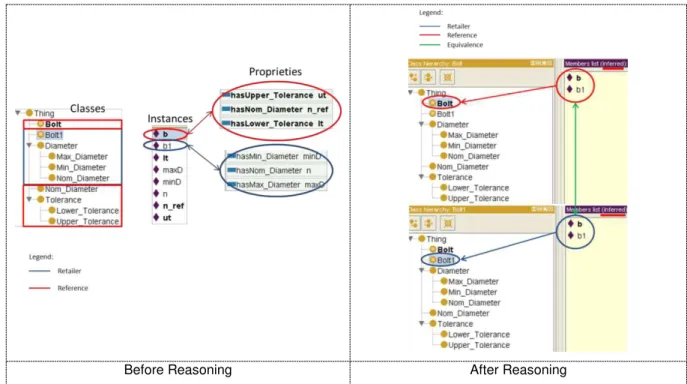
Figure 4.3 - Pellet reasoner output ... 44
Figure 4.4 - Reasoning Example (Retailer Ontology) ... 45
Figure 4.5 - Reasoning Example (Retailer and Reference Ontologies) ... 47
Figure 4.6 - Reasoning Example (Manufacturer and Reference Ontologies) ... 47
Figure 4.7 - Multiple Conceptual Semantic Checking Example ... 50
Figure 4.8 - ENSEMBLE scenario overview ... 51
Figure 4.9 - EISB Reference Ontology ... 52
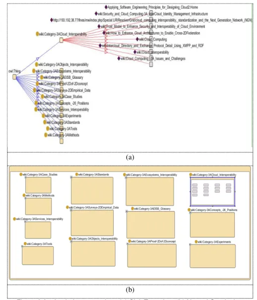
Figure 4.10 - (a) FInES wiki Main Page; (b) FInES wiki article example ... 53
Figure 4.11 - EISB Reference Ontology and FInES Wiki Structural Comparison ... 55
Figure 4.12 - Ontology/Wiki Synchronization (a) Using Web Services; (b) Using XML/RDF Files ... 55
Figure 5.1 - Synchronization tool architecture ... 60
Figure 5.2 - Example of changes recorded in the ChAO ontology ... 61
Figure 5.3 - Wiki DB example ... 62
Figure 5.5 - FInES Wiki: EISB Scientific Areas and Glossary ... 63
Figure 5.6 - FInES Wiki: (a) EISB Glossary; (b) Scientific Area category page example ... 63
Figure 5.7 - FInES Wiki: Scientific Area page example ... 64
Figure 5.8 - FInES Wiki: Sub Scientific Area page example ... 64
Figure 5.9 - FInES Wiki: EI Ingredient page example ... 65
Figure 5.10 - FInES Wiki: Publications page example ... 65
Figure 5.11 - EISB Reference Ontology overview ... 72
Figure 5.12 - Ontology to Wiki Synchronization execution flow ... 74
Figure 5.13 - Wiki to Ontology synchronization execution flow... 75
Figure 6.1 - Synchronization tool GUI ... 77
Figure 6.2 - Ontology to Wiki Synchronization - New Scientific Area instance detection ... 79
Figure 6.3 - Ontology to Wiki Synchronization - Scientific Area instance ... 79
Figure 6.4 - Ontology to Wiki Synchronization - New Scientific Area instance finished synchronization ... 80
Figure 6.5 - Ontology to Wiki new Scientific Area synchronization example ... 80
Figure 6.6 - Ontology to Wiki Synchronization - Deleted Class detection ... 81
Figure 6.7 – EISB Reference Ontology (a) Before class deletion; (b) After class deletion ... 81
Figure 6.8 - Ontology to Wiki Synchronization - Wiki page deletion (Java GUI) ... 82
Figure 6.9 - Ontology to Wiki Synchronizaton. (a) Wiki page before deletion; (b) Wiki page after deletion ... 83
Figure 6.10 - Wiki to Ontology Synchronization example - New publication detection ... 84
Figure 6.11 - Wiki to Ontology synchronization example - Publication to be synchronized ... 85
Figure 6.12 – Finished wiki to ontology synchronization process: (a) - java GUI; (b) Created instance ... 86
Figure 6.13 - Wiki to Ontology new publication synchronization example ... 86
Figure 6.14 - Wiki to Ontology Synchronization example - Edited Scientific area detection ... 87
Figure 6.15 - Scientific area page - (a) Before editing; (b) After editing ... 88
Figure 6.16 - Edited Scientific Area Synchronization - (a) Instance before editing; (b) Instance after editing; (c) Finished process - Java GUI... 88
L
IST OF
T
ABLES
Table 2.1 - Comparison between Ontology management tools ... 13
Table 2.2 - Comparison between ontology visualization tools ... 19
Table 2.3 - Ontology Reasoners Comparison ... 24
Table 3.1 - Semantic Mismatches [51] ... 36
Table 3.2 - Semantic Checking Framework... 38
Table 4.1 – Framework applicability scenarios ... 41
Table 4.2 - Retailer Ontology Terms and Definitions ... 42
Table 4.3 - Manufacturer Ontology Terms and Definitions ... 42
Table 4.4 - Reference Ontology Terms and Definitions ... 43
Table 4.5 – Retailer Reference Mappings ... 46
Table 4.6 - Manufacturer - Reference Mappings ... 46
Table 4.7 - Reference - Manufacturer Conceptual Mappings ... 48
Table 4.8 - SWRL rules defined in the retailer - reference example ... 48
Table 4.9 - SWRL rules defined in the manufacturer - reference example ... 49
Table 4.10 - Identification of conceptual losses in information ... 50
Table 6.1 - Ontology to Wiki synchronization cases analysis ... 78
A
CRONYMS
API - Application Programming Interface
ChAO –Changes and Annotations Ontology
CTM –Compact Topic Maps
DB –Database
EI –Enterprise Interoperability
EISB - Enterprise Interoperability Science Base
ENSEMBLE - Envisioning, Supporting and Promoting Future Internet Enterprise Systems Research through Scientific Collaboration
FInES –Future Internet Enterprise Systems
GUI –Graphical User Interface
HTML –Hypertext Markup Language
JDBC –Java Database Connectivity Driver
JVM - Java Virtual Machine
KB –Knowledge Base
KRE –Knowledge Representation Element
LTM –Linear Topic Maps
MENTOR - Methodology for Enterprise Reference Ontology Development
MO - Mediator Ontology
OWL –Web Ontology Language
RDF –Resource Description Framework
SHRIMP –Simple Hierarchical Multi-Perspective
SQL - Structured Query Language
SWRL - Semantic Web Rule Language
TM4L - Topic Maps 4 E-Learning
XML –Extensible Markup Language
1. I
NTRODUCTION
Nowadays, in an increasingly global business environment, several companies have found that to make themselves more competitive and productive they have to collaborate with other enterprises, to compete with the larger organizations [1]. However the globalization that led to the collaboration between companies, also led to the development of various Knowledge Representation Elements (KREs), such as ontologies, which are not semantically coincident [2]. As a result enterprises are engaging in some standstills regarding the lack of interoperability of systems and software applications to manage and increase their collaborative business.
Since various companies that operate in the same domain may have different representations of a same Knowledge Base (KB), when they describe it electronically it will most likely lead to different representation models [1]. Thus interoperability problems, particularly regarding the semantics of the concepts involved, may surface when these different systems try to exchange or share information with one another.
Even after having established seamless communication and semantic alignment between systems it
was identified the necessity of having “something” that allows companies to track their semantic evolution to keep the consistency and validity of their KREs. Since this is a vast and complex subject, it was recognized that a structured solution that encompasses several different scenarios was a possible step forward in help solving some of the semantic interoperability problems. Therefore the idea of a framework was conceived. A framework is a structure for supporting or enclosing something else, especially a skeletal support used as the basis for something being constructed [3].
To this effect, an interoperability framework that provides a set of assumptions, concepts, values and practices (methods & tools) [4] and that contemplates several scenarios for the semantic checking is a possible solution to the semantic interoperability maintenance issue.
1.1. Background Observation
Since interoperability between enterprises is becoming increasingly important to assure competitiveness and productivity, there is a need to constantly verify if the involved systems remain interoperable, particularly on a semantic level. For this reason, there is a need to have validation elements to ensure this interoperable state.
1.2. Motivation
Although some work has been done in the Enterprise Interoperability (EI) field, these focus more on the seamless interoperability between enterprises rather than verifying the consistency of the exchanged information. In fact a research roadmap (Enterprise Interoperability Research Roadmap) has been defined with the main objective of identifying the main areas of research within the EI domain [5]. As a consequence, one of the great motivations for this dissertation work is the fact that the semantic interoperability between businesses and enterprises is an authentic research challenge and it is a research area that is in constant contact with the industrial world.
Furthermore, enterprises would benefit greatly if it is assured that the information they exchange, besides being received, is also well perceived by others, since communication would be made with much less effort.
Therefore this works aim is to provide a possible solution in the field of semantic interoperability, with focus on the verification of the semantic consistency of information, by proposing a framework to serve as a backbone in solving these issues.
1.3. Research Method
The research method adopted in this work is centred on the classical method, which is composed by seven steps, conveniently ordered from a more theoretical to a more practical view of the system, in addition to an eighth step which is the passage from the theoretical work to the industrial world. This research method starts by defining the research theme and area and leads to the testing step and results analysis. Since this method is iterative, the researcher can go back to the first steps if the
obtained results weren’t the expected ones to try a new approach. Figure 1.1 represents the different steps of this method that are described afterwards.
study that intends to define the area of interest of the research. The research question must be clearly defined, making the study feasible and capable of being validated or refuted. Furthermore, a research question can be complemented with several minor questions to refine the main idea of the research subject. This is presented on section 1.4 - Research Questions and Problems.
2. Background / Observation: This step contemplates the study of the work done before about the same research area. In other words, this is where the state of the art research takes place. This is accomplished by reviewing literature and scientific projects bringing up the ideas of what was already tested and accomplished. Furthermore it is important to have a big variety of documents for searching information on the area of interest, since some of the literature although very reliable, can be outdated and on the other hand, some documentation can be recent and have very innovative ideas but low reliability. Finally, it is also in this step that the researcher defines what differs from the previous work to the one being developed, as well as the methodologies taken when approaching the solution.
The background observation (state of the art study) is comprehended in sections 2 and 3 of this dissertation.
3. Formulate Hypothesis: As its name indicates, in this step the researcher formulates the hypotheses in order to make the research problem simpler to understand, stating the ambitions to accomplish at the end of the project. The hypothesis can be seen as an educated guess since it states the predicted relationship amongst variables.
The hypotheses for this research work are presented in section 1.5 of this document.
4. Design Experiment: This step works as a preparation for the experimental step, where a prototype or system architecture is designed. In addition, it is significant to find a validation plan for the previous step, i.e. the hypothesis.
5. Test Hypothesis: This step comprehends the implementation of the designed prototype and the evaluation of the obtained results. A large amount of tests (especially in different scenarios) should be done in order to test effusively the outcomes given by the system. These outcomes are supposed to be collected for later analysis.
possible to consider what comes after, making some recommendations for further research. But even if the results are not what was expected it should not be taken as a failure, but as an opportunity to improve the original approach and go back again to the first steps of this research method. The researcher can then try a different approach from the one taken before.
7. Publish Findings: The final results, if consistent, must end up in a valuable contribution to the scientific community as scientific papers. These papers can be then presented in conferences, where the author has the chance to show in person his ideas for the research, presenting the results and answer questions of other researchers to prove the efficiency of the results.
8. Transition to Industry: Upon validation from the scientific community, the conducted work should be analysed for a possible industrial application in order to capitalize from it and contribute to the entrepreneurial world. This can be accomplished by passing the developed work from a prototype stage to a fully functional industry application which can be presented to various enterprises and businesses.
1.4. Research Questions and Problems
How can the semantic consistency of the data exchanged between enterprises information systems be checked?
1.5. Hypothesis
With a proper framework that provides guidelines for semantic consistency checking complemented with possible resolutions for each case, the data exchange between enterprises is facilitated and its understanding maintained.
1.6. Dissertation Outline
Section 3 is named Semantic Checking Framework and covers a background research about interoperability and consistency checking in ontologies. Furthermore this section introduces the framework that is proposed in this work as a solution to the semantic checking of information systems issue.
The next section (4), Application Scenarios, describes two situations where the proposed framework was applied. Firstly a mechanical scenario is presented, that features the interaction between a bolt retailer and a manufacturer. The second scenario refers to the Envisioning, Supporting and Promoting Future Internet Enterprise Systems Research through Scientific Collaboration (ENSEMBLE) project. The described scenarios were also used to demonstrate the validity of the ideas presented in this work.
Section 5 is called Proof-of-Concept Implementation and as its name indicates, features the architecture of the developed prototype, the technologies used to develop it and why they were chosen. Furthermore it is presented the execution flow of the prototype to serves as a complement to the architecture in the sense that it shows in detail the flow of the system. Furthermore, this chapter presents and describes in detail the involved elements in the system, namely the EISB (Enterprise Interoperability Science Base) Reference Ontology and the FInES (Future Internet Enterprise Systems) wiki.
The following section is the Synchronization Tool Demonstration chapter which shows the results of the implemented prototype by featuring some execution examples of the developed prototype.
2. O
NTOLOGY
B
ASED
S
OLUTIONS FOR
K
NOWLEDGE
R
EPRESENTATION
This chapter comprehends the state of the art study regarding ontology operations, reasoners and management and visualization tools. This study focuses mainly on ontologies since they are capable of encoding the knowledge of a certain domain in machine-processable form to make it available to other information systems [7]. Therefore ontologies have been widely adopted as mechanisms to represent knowledge on a given domain.
This chapter is structured as follows; firstly, some ontologies operations are presented and described, as well as the concept of ontology learning. Following is the study of selected ontology management and visualization tools. Finally, the review of certain ontology reasoners is presented.
2.1. Ontology Operations & Learning
Ontology operations usually refer to the methods used to integrate two or more ontologies, while ontology learning refers to the fact of extracting ontological elements in order to build new ontologies. A summary of the ontology operations that are going to be discussed in detail in the following sub-sections are:
Ontology mapping/matching;
Ontology alignment;
Ontology merging;
After the execution of any of these operations the user should check the resulting ontology for inconsistencies or loss of information [8].
To conclude this subsection, the concept of ontology learning is described and presented in detail.
2.1.1. Ontology mapping/matching
As referred by the de Bruijn et al in [9], ontology mapping is a (declarative) specification of the semantic overlap between two ontologies.
This operation consists in mapping or matching each entity (class, relation, attribute, etc.) of an ontology to the corresponding entity in another ontology, as illustrated in Figure 2.1. The corresponding entities must have the same meaning, which means that usually the correspondences are expressed in a one-to-one fashion. This process won’t modify the involved ontologies, and as a
Figure 2.1 - Ontology mapping/matching
2.1.2. Ontology alignment
Much like the mapping process, in the alignment operation the original ontologies persist with links established between them [10], which is why this operation is often considered a synonym of ontology mapping. However, the original ontologies might suffer alterations because this process implies a mutual agreement between the ontologies in order to make them aligned and coherent with one another, eliminating unnecessary information [8]. This is why this method is usually applied when the involved ontologies cover domains that are complementary to each other. This way the original ontologies are more likely to remain unaltered diminishing the likelihood of occurring inconsistencies of information. As illustrated in Figure 2.2, the two original ontologies (A and B) were aligned so that the resulting ontology of the operation, in this case, consists of the greyish area of ontology A.
Figure 2.2 - Ontology alignment
2.1.3. Ontology merging
The process of ontology merging consists in integrating or merging two or more existing ontologies to form a new ontology. In this operation, the source ontologies are usually discarded and only the new ontology remains active. Although in some cases the source ontologies could also remain active after the merging process. In the merging operation, often the original ontologies cover similar or overlapping domains [10] .
Figure 2.3 - Ontology merging
Figure 2.3 shows a small example where ontologies A and B are merged together to form a new ontology (C) that consists of the source ontologies.
It is worthy of note that the result of the merging process (or any other that promotes changes to the ontologies) should be tested in order to identify inconsistencies or loss of information [8].
2.1.4. Ontology Learning
Ontology Learning refers to extracting ontological elements (conceptual knowledge) from input and building an ontology from them [11]. Furthermore, within the research community, ontology learning is mainly associated to the process of discovering ontological knowledge from various forms of data [13]. According to Cimiano et al in [12] there are three kinds of data to which ontology learning can be applied, which are, structured data (e.g. databases), semi-structured data (e.g. HyperText Markup Language - HTML or Extensible Markup Language - XML) and unstructured data (e.g. text) documents. However, it can also be used as support to the refinement and expansion of existing ontologies that could have been built following a traditional basis by means of incorporating new knowledge in an automatic way [13].
To achieve the goal of discovering ontological knowledge from various forms of data, diverse ontology learning techniques have been developed. These serve the purpose of supporting an ontology engineer in the task of creating and maintaining an ontology [12]. Most of these techniques are drawn from well-established disciplines such as machine learning, natural language processing, statistics, knowledge acquisition, information retrieval, artificial intelligence, reasoning and Database (DB) management [11][14]. However these techniques are not exclusive to one another, i.e., they can be combined to form a more powerful method to achieve the goals of ontology learning. For example, linguistic-based methods are commonly applied with statistical approaches to calculate the relevance of concept to the given domain, these methods include techniques based on linguistic patterns, pattern-based extraction, methods that measures the semantic relativeness between terms within a domain.
2.2. Ontology Management Tools
other operations on ontologies. As referred by Youn, S et al in [15], ontology tools can be applicable for all stages of the ontology life cycle (creation, population, validation, deployment, maintenance and evolution). These tools support a variety of ontology languages such as the Web Ontology Language (OWL), Resource Description Framework (RDF) or XML which are used to implement the ontologies. In this subsection three ontology management tools are presented, Protégé, Ontopia and Topic Maps 4 E-Learning (TM4L), although there are many more.
2.2.1. Protégé
Protégé is a free, open-source platform, with a suite of tools to construct domain models and knowledge-based applications with ontologies [16]. This tool allows the user to perform numerous ontology operations, such as creating, populating, validation or visualization. It also enables the creation of domain ontologies, definition of classes, class hierarchies, variable-value restrictions, and the relationships between classes and the properties of these relationships [16]. Apart from these features, Protégé also allows the user to export or import ontologies provided they are in OWL/XML or RDF/XML formats. Regarding the Graphical User Interface (GUI), Protégé consists of a tab navigation system, much like a web browser, allowing for a much smoother learning curve. Navigating through the tabs the user can easily see the entities, classes, instances and relations that compose the ontology, as illustrated in Figure 2.4.
Figure 2.4 - Snapshot of the Protége GUI
2.2.2. Ontopia
using a user-friendly web interface, as shown in Figure 2.5. The Ontopoly editor also provides the user the possibility to populate the ontologies and to store them in files or databases [19].
Figure 2.5 - Ontopoly snapshot
The second main component of Ontopia is the ontologies browser called Omnigator and has a variety of features. It is web-based and can be used to display any topic map [20], as illustrated in Figure 2.6, whether the topic map was created with the Ontopia editor (Ontopoly) or imported from another ontology editor (e.g. Protégé). Additionally, the Omnigator also features an exportation plugin, that allows saving the ontology into various file formats such as RDF, XML Topic Maps (XTM 1.0, 2.0 or 2.1) or Linear Topic Map (LTM), a topic map query interface, topic maps validation, statistics and merging. One great advantage of this tool is that it allows the user to follow links associated to classes or instances. For example, navigating to a class through omnigator one could follow the link associated with that class and be redirected to the designated web page.
(a) (b)
Figure 2.6 – Omingator snapshots - (a) Omnigator Main Page with index of topic maps; (b) Browsing a topic map
Finally, the third main component of the Ontopia tool suite is the graphical visualization feature named Vizigator (visual navigator). Since section 2.3.1 is dedicated to this component, there won’t be a
show graphical visualizations of topic maps and is subdivided in two components, the VizDesktop and the Vizlet.
2.2.3. TM4L
The TM4L tool is somewhat similar to Ontopia, in a sense that it also uses the topic maps technology to manage ontologies. However, Ontopia is web-based and TM4L is more of a “standalone” or “offline”
product. This tool provides support in conceptual structure design and maintenance through its functionality for editing, browsing, and combining such structures, coupled with support for relating concepts, linking concepts to resources, merging ontologies, external searching for resources, defining perspectives, etc.[21]. TM4L has a user-friendly interface, which guides the users to create and update topic as well as their relations and resources [21]. This tool is divided into two constituents, the editor and the viewer.
The TM4L editor is what allows the user to create, edit and manage ontologies using topic maps. About formats, TM4L saves the topic maps in the XTM format by default, however TM4L comes equipped with a XTM to RDF converter granting compatibility with RDF applications, such as Protégé, for example. Since this is as topic maps based tool, the main objects it manipulates are topics (representing domain ontology concepts), relationships between them, resources, and contexts (represented by themes) [21]. Regarding the user interface, TM4L uses a tab navigation system, as seen in Figure 2.7 similar to the one used in Protégé, from which the user can access the topic map, the topics, relationships, themes and the graphical visualization of the topic map.
Figure 2.7 - Snapshot of TM4L user interface
2.2.4. Ontology Management Tools Concluding Remarks
In conclusion of this section, Table 2.1 is presented in which a comparison of the main features of the described ontology management tools is conducted. Namely, the characteristics being compared are the supported file formats for import and export and if the management tool provides means for a graphic visualization of ontologies.
Table 2.1 - Comparison between Ontology management tools
Ontology Management
Tool
Import
Format Export Format Graphic Visualization
Protégé RDF, OWL
RDF/XML,OWL/XML in all versions. In versions 3.4.x, CLIPS, N-TRIPLE, N3, TURTLE. In versions 4.x, KRSS2, OBO 1.2, Latex.
Yes.
In versions 3.4.x through plugins like Jambalaya. On versions 4.x through plugins like OntoGraf
Ontopia
RDF, XTM, CTM, TM/XML
XTM 1.0, XTM 2.0, XTM 2.1, RDF/XML, CXTM,
LTM and TM/XML
Yes, through the Vizigator tool
TM4L
XTM , RDF (though to work RDF must be converted to
XTM)
XTM, RDF (through the XTM to RDF converter
tool)
Yes, through the TM4L Viewer
As seen in this table, they all seem to be very complete, since they all provide support for various file types and graphical visualization methods. However, Protégé is more adequate for beginning ontology development since it has a more user-friendly interface and has a smoother learning curve. Nonetheless, the choice between which tools to use should come down to the needs of each user. If topic map technology is used, then Ontopia and TM4L are best suited, with Ontopia being more complete, specifically regarding the supported file formats. On the other hand, if OWL or RDF files are used to store the ontology then Protégé is the best choice.
2.3. Ontology Visualization
Ontology visualization refers to the graphical visualization of ontologies. These representations can be accomplished by means of directed or nested graphs, topic maps or other techniques. However this
isn’t an easy operation to accomplish, because ontologies are more than just a hierarchy of concepts [22]. They are the sum of various relations and attributes between classes and entities, and in turn, these can have a wide number of instances, so it can be difficult to represent ontologies effectively. It is worthy of note that the examples used to take the snapshots for the figures were taken from the FInES wiki [23], upon extraction of its contents to an RDF file. The examples will highlight the cloud interoperability wiki category (class) and all of its pages (instances).
2.3.1. Ontopia Vizigator
The Vizigator (visual navigator) is an ontology visualization tool from the Ontopia tool suite that displays ontologies in form of topic maps, as illustrated in Figure 2.8
It shows graphical visualizations of the structure of a topic map for seeing larger patterns in complex data, or simply as a visually attractive and user-friendly alternative way of displaying the topic map [24].
It was also said in the Ontopia dedicated section that the Vizigator tool has two main components, the VizDesktop and the Vizlet. The first component provides a graphical interface where the user can load a topic map or ontology to display, in a variety of formats including RDF, XTM, Compact Topic Maps (CTM) and LTM, and configure the visualization through a set of operations like filtering and scoping. These options enable the user to configure which associations, classes or instances to show, or what colours and shapes represent the various components of the ontology. In short the user can fine tune the display to ensure the best results. The second component refers to a Java applet for displaying visualizations on the web which is called the Vizlet [24] .
Setting up the visualization requires no programming, the user only has to create a configuration in VizDesktop and deploy the applet together with the necessary web service interface on the server side [24].
Figure 2.8 - Ontopia Vizigator snapshot
2.3.2. Jambalaya
The Shrimp visualization technique uses a nested graph view to present information that is hierarchically structured. It introduces the concept of nested interchangeable viewsto allow a user to explore multiple perspectives of information at different levels of abstraction [25].
In Jambalaya, there are many types of views available. The user has choices that range from the nested graph to the sink tree views. Furthermore the user is able to choose the layout of those views, such as radial or grid layouts. The classes and instances are represented as nodes in the graph. However they are represented differently according to view type chosen, as shown in Figure 2.9. In the nested view, the classes (or instances) are represented within the class they belong to, that is they are nested inside their superclass node. As for the sink tree view, the classes and instances are still represented as nodes, though the relations are represented by directed arcs connecting them. Apart from this visualization features, Jambalaya also allows the user to filter contents of the visualization, to search for a specific class, instance or relation or zoom in or out for a more detailed or more generic view. These features result in an environment where the user can interact directly with the information space enhancing their understanding of the information structures, thus promoting further exploration [25].
(a)
(b)
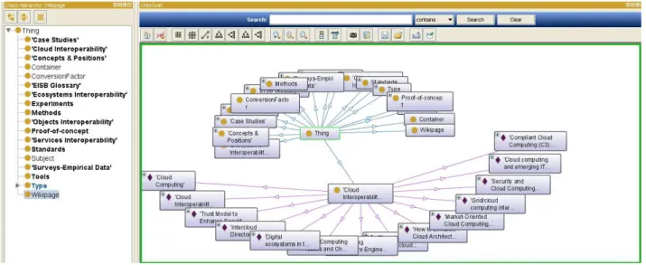
2.3.3. OntoGraf
The OntoGraf is an ontology visualization tool available as a plugin for Protégé versions 4.x. It gives support for interactively navigating the relationships of OWL ontologies and it also supports various layouts for automatically organizing the structure of the ontology [26]. Much like the other visualization tools described, OntoGraf displays all information regarding a class (subclasses, instances, etc.) and it also represents the various relationships which are represented by directed arcs and differentiates them through different colours.
It is a very similar tool to Jambalaya since it provides similar views, however it doesn’t feature the
nested graph view (figure 2.9 (b)). On the other hand it is able to better present complex information than Jambalaya as one can see by comparing Figure 2.9 (a) and Figure 2.10 that represent exactly the same scenario gathered from the FInES wiki [23]. Jambalaya depicts a confusing scenario, where the labels of the classes and instances are all overlapping. On the contrary OntoGraf is able to keep things very neat, clearly representing all the classes and instances with the labels being completely readable and all the relationships also clearly visible.
Figure 2.10 - OntoGraf snapshot
2.3.4. TM4L Viewer
By choosing a member of a list, the TM4L Viewer automatically displays the graph and the tree of the selected object, as illustrated in Figure 2.11.
Figure 2.11 - Snapshot of the TM4L Viewer
2.3.5. DebateGraph
DebateGraph [27] is a web-based collaborative idea visualization tool based on mind maps. This visualization tool displays topics or ideas that relate to a selected topic. It enables several users to contribute to a topic by adding their own ideas and contributions that can be represented in different colours depending on the user point of view. For example, the green colour is used when the user has a positive argument about a certain topic, or a red colour when the argument is against a certain point of view. It also enables the user to create subtopics that can represent instances, or subclasses of a certain class (topic). A major advantage of this tool is the possibility of easily sharing the map with others via web pages through the addition of specific HTML code provided by the DebateGraph GUI. Another advantage of this tool is that it provides excellent readability of the concepts, even when dealing with very large and complex maps, i.e. the topics are clearly visible and their labels aren’t
stacked upon each other and can easily be read. However, a big disadvantage of this tool is the fact
that it isn’t possible to open or exporting map files, which means that the user either creates a new
Figure 2.12 - Snapshot of the debateGraph visualization tool
2.3.6. TheBrain
This tool is based on the mind map technology and can be used as a mean for ontology visualization. It uses a graphical layout of topics connected by lines that radiate out from a central topic [28]. However it is a very dynamic tool since any topic can be the central one as the user shifts contexts or changes the focused topic. Up to this point, the Brain tool seems very similar to the other ontology visualization tools already presented. However this tool has some features that the others do not. One
of these features is the possibility of attaching files or URL’s to each topic allowing the user to be
redirected to those sources thus providing complementary information about the topic. Another important feature is the possibility of uploading and sharing the created mind map to a website using simple HTML code, thus allowing other users to navigate online through the map. Figure 2.13 represents the same example gathered from the FInES wiki that was used in the previous ontology visualization tools. As can be seen, this tool centres the focused topic and arranges the other topics neatly in the side so that they can easily be selected if the user so desires.
2.3.7. XMind
XMind is an open source tool that contributes to building a cutting-edge brainstorming/mind-mapping facility, focused on both usability and extendibility [29]. The structure in XMind contains a root in the center, with main branches radiating from it, similarly to “theBrain” tool. Its features contemplate several mind map templates, the ability to import and export mind maps in a variety of file formats and it can also be shared on the web or embedded in a webpage [30]. This tool can be of great use in terms of ontology visualization because the information can be arranged as to maintain good
readability and more importantly it can clearly represent the class hierarchy, as well as the properties that relate the several classes. However a major downside to this tool is that it doesn’t work with
ontology files such as, OWL or RDF, thus the classes and properties have to be built manually, which for complex ontologies, can be very error-prone and extenuating.
Figure 2.14 shows an example gathered from the FInES wiki, and as can be observed, it contains a root topic, and its branches represent classes, while the blue dotted lines represent the relations between them. This example can attest to the capability of this tool to represent the relations and class hierarchy of an ontology, although this is mainly a mind mapping tool.
Figure 2.14 - Snapshot of the XMind visualization tool
2.3.8. Ontology Visualization Tools Concluding Remarks
To conclude this section Table 2.2 is presented, where the studied ontology visualization tools are compared regarding their supported file formats, possibility of embedding the visualization online, support for multiple users and elements disposition and readability.
Table 2.2 - Comparison between ontology visualization tools Ontology
Visualization Tool
Supported File
Formats Online Embedding
Multiple Users
Support Readability
Ontopia Vizigator XTM, CTM, LTM, RDF and TM/XML
Yes. Through Java applet + web service
interface Yes Medium
Jambalaya OWL 1.0, RDF No N.A. Bad
OntoGraf OWL, RDF No N.A. Medium
TM4L Viewer XTM and LTM No N.A. Medium
DebateGraph N.A. Yes Yes Good
theBrain
XML, DOCX, MMAP, XMMAP, OPML, MM,
OWL and TXT Yes Yes Good
XMind XMIND, MMAP, XMP and MM Yes Yes Good
arcs. However when their specifications are more thoroughly analysed, differences between them begin to emerge, as shown in the table. Beside these differences, one cannot clearly state that a tool is better than the other. Still, depending on the technology used to develop the ontologies or their end use, some tools can be more suited than others. For example, if topic map type files are used then
perhaps it is best to use Ontopia’s Vizigator or the TM4L Viewer. On the other hand if the ontologies are developed using the OWL or RDF file formats then the Jambalaya and OntoGraf tools are perhaps more suited for a better visualization. Furthermore if the end use for the visualization is an online application then DebateGraph or theBrain or even XMind are more suited as they offer a more simple solution for online integration. The multiple users feature relates to the capability of the tool to support users editing or viewing the ontology at the same time. Unfortunately this feature could not be tested for the Jambalaya, OntoGraf and TM4L viewer tools, hence the “Not Applicable” (N.A.) value Lastly
there’s the readability attribute, which is evaluated according to three levels, “bad”, “medium”, and “good”. The lowest value is “bad” and means that the elements aren’t clearly shown or the labels
aren’t read easily, signifying that the concepts are piled on top of each other creating a lot of confusion and not allowing a good overview of the structure of the ontology. The “medium” value means that the
concepts are still presented somewhat confusingly, however it is possible to have a better overview of the ontologies structure. The highest value for this attribute is “good” and it means that the elements
are neatly shown, all the labels are easily readable and the structure of the ontology is well represented. It is also worthy of note that the readability attribute refers to large or complex ontologies, since for simple or small ontologies, all of the tools perform satisfactorily.
2.4. Ontology Reasoners
Reasoners are key components for working with OWL ontologies. In fact, querying an ontology should be done using reasoners. The reason for this is that knowledge in an ontology might not be explicit and a reasoned is required to deduce implicit knowledge so that the correct query results are obtained [31]. These tools work based on description logic, where logical consequences are inferred, using an inference engine, based on a predefined set of rules and are often based on a hypertableau algorithm [32]. Reasoners are often used paired with ontology editing tools, like the ones previously presented, with the objective of computing the class hierarchy and alert users to inconsistencies within the ontology [33].
In this subsection four of the most known description logic reasoners will be presented, HemiT [34], Pellet [35], FaCT++ [36] and RacerPro [37].
2.4.1. HermiT
the command line or in java applications [39].
HermiT as Protégé plugin
In this mode of operation, HermiT can be accessed directly from the Protégé GUI from a drop down menu on the menu bar. When the reasoner is run the consistency of the ontology is assessed. If the ontology is inconsistent, a pop up message appears to alert the user to that fact, as shown in Figure 2.15. On the other hand, if the ontology is consistent, the results can be seen by choosing to view the inferred components from the Protégé GUI as illustrated in Figure 4.4.
Figure 2.15 - HermiT reasoner Protégé plugin output - inconsistent ontology
Using HermiT from the command line
When HermiT is used from the command line, different common reasoning tasks can be configured for the reasoner to perform. In the example featured in Figure 2.16 HermiT was used to classify an
ontology, outputting the class hierarchy. The command to invoke HermiT from a shell is “java –jar
HermiT.jar” followed by the arguments that serve to tell which operation the reasoner is to perform.
Using HermiT in java applications
This reasoner can be used in java applications through the OWL Reasoner interface that is available in the OWL Application Programming Interface (API). It can be used to integrate HermiT with user developed applications or tools. In the example shown in Figure 2.17, a simple demo application was created where the consistency of an ontology is tested. If the ontology is consistent the program
returns the Boolean value “true”, else if it isn’t consistent the program returns the Boolean value “false”.
Figure 2.17 - HermiT reasoner java application integration example
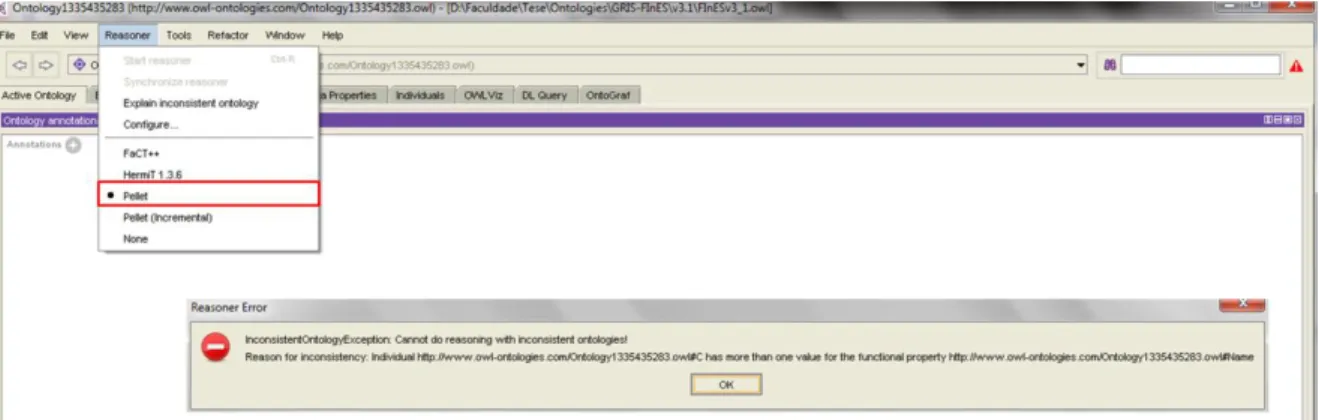
2.4.2. Pellet
Pellet is an OWL description logic reasoner that features standard reasoning services, such as, consistency checking, concept satisfiability, classification and realization [40]. As it happens with the HermiT reasoner, Pellet also has multiple interfaces from which users can access its reasoning capabilities, for instance, a command line interface, an API and as a Protégé plugin. The command line interface is more suited for simple reasoning tasks, while the API is better for standalone applications and the Protégé plugin is useful when the ontology is being developed using that editor.
An example of consistency checking of an ontology using this reasoner is shown in Figure 4.3.
Figure 2.18 - Pellet reasoner Protégé plugin output - inconsistent ontology
2.4.3. FaCT++
FaCT++ is also an open source OWL description logic reasoner that uses FaCT algorithms, but with a different internal architecture [36]. This reasoner can be used as standalone reasoner, as back-end reasoner for an OWL API based application [38] or as a plugin for the Protégé ontology editor. FaCT++ is implemented using C++ in order to create a more efficient tool, and to maximise portability [36]. As happens with the previously presented reasoners, FaCT++ is also capable of verifying the consistency of OWL ontologies and classifying the ontology to compute the class hierarchy.
The example featured in Figure 2.19, illustrates the output of the execution of the FaCT++ reasoner, as a Protégé plugin, on an inconsistent ontology.
Figure 2.19 - FaCT++ reasoner Protégé plugin output - inconsistent ontology
2.4.4. RacerPro
can be used on a standalone application via a Java or LISP API. Its main functionalities include [41]:
Check the consistency of an OWL ontology and a set of data descriptions.
Find implicit subclass relationships induced by the declaration in the ontology.
Find synonyms for resources (either classes or instance names).
Incremental query answering for information retrieval tasks (retrieve the next n results of a query). In addition, RacerPro supports the adaptive use of computational resource: Answers which require few computational resources are delivered first, and user applications can decide whether computing all answers is worth the effort.
To have a better understanding of its features, Figure 2.20 is presented, which illustrates the technologies that this reasoner integrates and supports.
Figure 2.20 - RacerPro reasoner supported features [41]
2.4.5. Ontology Reasoners Concluding Remarks
As a conclusion to this subsection Table 2.3 is presented where some features of the presented
reasoners are put side by side for a better general view. It isn’t the objective of this work to make an
exhaustive comparison of these reasoners, but it is suffice to say that these tools are quite similar to each other varying only in their architectures, implementations and speed of execution of the reasoning tasks.
Table 2.3 - Ontology Reasoners Comparison
Ontology
Reasoner User Interface
Ontology Consistency
Checking
Ontology Classification
Standalone applications
integration
HermiT Protégé plugin,API Command line, Yes Yes Yes
Pellet Protégé plugin, API Command line, Yes Yes Yes
FaCT++ Command line,
Protégé plugin Yes Yes N.A.
RacerPro Protégé plugin, API Yes N.A. Yes
RacerPro doesn’t implement this feature. An API is particularly useful when integrating reasoning
features to user developed applications. Out of the studied reasoners, only FaCT++ doesn’t implement
this feature. Regarding the consistency checking of ontologies, all of the reasoners are capable of
doing so, since it’s their main objective. Referring to the classification of an ontologies taxonomy, only RacerPro doesn’t have this capacity. Finally, the integration of reasoning features with standalone applications isn’t accomplished by FaCT++ since it doesn’t provide an API.
3. S
EMANTIC
C
HECKING
F
RAMEWORK
In this chapter, the semantic checking framework proposed by the author is presented along with an extensive description of its purpose and guidelines. In addition, to provide a context as to why and how this framework was developed, a background study on the problematic of systems interoperability and consistency checking is also presented. This study is important because it introduces key concepts to the problematic addressed in this work such as, consistency checking and semantic checking.
3.1. Interoperability
According to the IEEE standards glossary [42] interoperability is the ability of a system or a product to work with other systems or products without special effort on the part of the customer. Still, the popular perception is that interoperability is synonymous with connectivity. However, interoperability is much more than just connectivity. It is also a function of operational concepts and scenarios, policies, processes and procedures [43]. Nonetheless, there are other definitions of interoperability such as the one in [44], which regards interoperability as the ability of a set of communicating entities to exchange specified state data and operate on that state data according to specified, agreed-upon, operational semantics. Interoperability can also be seen in an EI point of view being defined as the ability of interaction between enterprises. The enterprise interoperability is achieved if the interaction can, at least, take place at the three levels: data, application and business process [45]. Despite these different definitions, the one adopted in this work is the one defined in [44] as it is deemed by the author as the most suitable to the topic of this dissertation.
Nowadays, as information systems in enterprises and organizations keep evolving and become more complex, the need for interoperable operation, automated data interchange and coordinated behaviour of large scale infrastructures becomes highly critical [46]. Regarding enterprise systems as layered systems, to achieve meaningful interoperability between enterprises, interoperability must be achieved on all layers [47], as seen in Figure 3.1.
Yet, interoperability isn’t only a technical issue. The rise of other challenges have led to the
categorization of interoperability into several fields, such as, data, organizational, semantic, syntactic, etc. Data interoperability denotes the agreed format in which data is exchanged between collaborating enterprises. Organizational interoperability deals with the ability of enterprises to collaborate and exchange information despite having different internal structures and processes. Semantic interoperability offers cooperating enterprises the ability to bridge semantic conflicts arising from differences in implicit meanings, perspectives and assumptions by creating a compatible environment based on agreed concepts between the entities [48]. Syntactic interoperability allows multiple software components to cooperate regardless of their different implementation languages, interfaces or execution platforms [48].
There are several ways to achieve interoperability, either by implementing standards [42] or, in the case of ontologies, by performing operations to integrate them or by resorting to a methodology, such as MENTOR (Methodology for Enterprise Reference Ontology Development), to build a reference ontology to serve as a bridge between the source ontologies. However, it is needed to take into account that the execution of any operation can result, in some cases, in loss of information. Therefore, after conducting operations to integrate or to make two or more systems interoperable, it is needed to check the consistency of the output, independently of which type of interoperability considered.
3.2. MENTOR Methodology
MENTOR is a methodology that helps an organization to build and adapt a domain reference ontology [49]. MENTOR provides a methodology that allows ontology building from scratch, ontology reengineering, cooperative ontology building and ontology merging methods.
This methodology is comprised of two phases, each with three steps, as seen in Figure 3.2. The first phase (Lexicon Settlement Phase) represents the domain knowledge acquisition and is divided in the following steps:
Terminology Gathering – In this step all the relevant terms or concepts in a specific domain are gathered, with the all the participants giving their inputs [49]. The terms gathered in this step should reference the contributors so that they can provide their definitions during the next step;
Glossary Building – In this step, each contribute provides their annotations of the previously established terms. Then the terms enter a cycle where they are reviewed in order to reach a
reference definition. This cycle has two possible outputs. If there isn’t an agreement then the
into semantic proper paths in the existing taxonomic structure down to the thesaurus leafs [49]. Equally to the previous step, the process only advances if there is an agreement between
the participants. If an agreement isn’t reached then the cycles starts all over again. On the contrary, if there is an agreement then the thesaurus is produced and process advances to the next phase. The defined thesaurus will enhance the ontology harmonization process in the next phase [49].
The second phase (Reference Ontology Building Phase) is where the reference ontology is built and the semantic mappings between the organizational ontologies and the reference one are established [49]. This phase is composed by the following steps:
Ontologies Gathering – This step comprehends the collection of ontologies or other types of knowledge representation techniques within the specified domain;
Ontologies Harmonization – This step is supported by two cycles. First there is a discussion about the structure of the reference ontology where the previously defined thesaurus is taken into account. Once again, if an agreement is reached by all, then the cycle is repeated. If a consensus is reached then the taxonomy of the reference ontology is defined. From there the step advances to the second cycle where the contents of the gathered ontologies are harmonized using the semantic mismatches previously recorded. However new mismatches may be found and these need to be recorded as well. When the participants reach an agreement the reference ontology is finalized and the process can advance to the final step;
Figure 3.2 - MENTOR Methodology [49]
Some work has already been conducted by Gaspar in [50] in order to enrich MENTOR with qualitative information collective methods and developed a functioning prototype, illustrated in Figure 3.3 that implements some of the described steps.
3.2.1. Mediator Ontology
As previously referred, one of the steps in this methodology comprises the establishment of mappings to record the possible existing semantic mismatches. Since this is not an easy task, MENTOR uses a Mediator Ontology (MO) as a reference for mediating the mapping establishment and its subsequent
‘mapping records’ reasoning [50]. This allows communities to build systems with reasoning capabilities
able to understand each other’s representation format, without having to change their data and
communication functions [49]. Apart from the feature of enabling seamless communication between different systems, the MO is also able to represent ontology semantic operations such as, the semantic mismatches found in the Glossary building step, the semantic transformations identified in the harmonization process, the ontologies mapping and other ontology operations (e.g. versioning) [49]. To be able to represent these ontology operations, the MO is uses a five-tuple mapping expression proposed by Agostinho et al. in [51]. According to the tuple philosophy, all the information about the mappings should be stored in a dedicated KB so that it becomes computer processable and so that readjustments are easier to manage. In this case the KB is the MO which is defined in the OWL format with the structure represented in Figure 3.4.
Figure 3.4 - Mediator Ontology Structure [52]
The structure of the MO, presented in the previous figure is described as follows: the MO has two
main classes: “Object” and “Morphism”. The “Object” represents any “InformationModel” (IM) which is
used by several organizations to automatically transform and exchange data with their business partners [51].
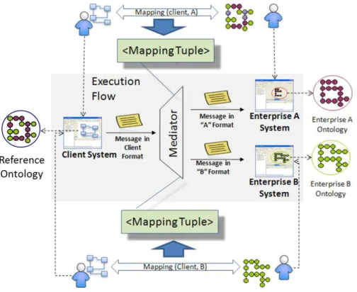
With the mappings stored in the mediator, all information regarding them can be accessed by local systems of business partners that wish to communicate. The translation from one message format to another is the responsibility of the mediator, therefore assuring seamless communication between different systems. Figure 3.5 illustrates the general vision of the flow of the system. At the beginning, all the required mappings, using the tuples, are established and stored in the MO. Then, when one of the business partners wants to communicate with another, it simply sends its message to mediator who is then in charge of transforming its format and forwarding it to the destination.
Figure 3.5 - Mapping design and execution flow in data exchange
3.3. Consistency Checking
strategies for detecting and repairing inconsistencies [56] and how to deal with the evolution of ontologies in order to maintain their consistency [55]. Other work that has been conducted in this area features tools to help prevent or detect and fix inconsistencies. Such tools are mostly descriptive logic reasoning tools that infer logical consequences, through an inference engine, based on a set of rules or facts. Examples of consistency checking tools are ConsVISor [57], FaCT++ [36] or HermiT [34].
Consistency checking can be divided into two categories that are referred here as interoperability checking and semantic checking. The latter being the main focus of this dissertation.
3.3.1. Interoperability Checking
As information systems in companies and enterprises evolve and grow larger and more complex, a previous interoperable state with other systems, within the same or between different companies, can become compromised. Therefore there is a necessity to continuously verify if the systems are still functioning properly with one another, i.e., if they remain interoperable. This is often done by using tests designed specifically to achieve this goal. From a general perspective, two types of testing are relevant in the entrepreneurial context, conformance and interoperability testing [58]. Conformance testing involves the verification of whether an implementation is in conformity with the underlying specifications. This kind of testing is the first step toward interoperability with other conformant systems as prescribed by the specification [58]. An example of conformance testing is shown in Figure 3.6.
Figure 3.6 - Conformance Testing Example [58]
Figure 3.7 - Interoperability Testing Example [58]
Also according to [58], software implementations can be certified and correct information exchange between systems if both types of testing are used, meaning that conformance testing isn’t a substitute
for interoperability and vice-versa. Furthermore, the quality of the interoperability specifications impacts the difficulty in the application of the tests.
3.3.2. Semantic Checking


![Figure 3.2 - MENTOR Methodology [49]](https://thumb-eu.123doks.com/thumbv2/123dok_br/16580455.738520/48.893.206.736.110.635/figure-mentor-methodology.webp)
![Figure 3.4 - Mediator Ontology Structure [52]](https://thumb-eu.123doks.com/thumbv2/123dok_br/16580455.738520/49.893.136.766.515.901/figure-mediator-ontology-structure.webp)