American Journal of Applied Sciences 5 (2): 129-135, 2008 ISSN 1546-9239
© 2008 Science Publications
Corresponding Author: Full-Professor of Biomedical Engineering, Artificial Tactile Sensing and Robotic Surgery Lab, Department of Biomechanics, Faculty of Biomedical Engineering, Amirkabir University of Technology, Tehran, Iran, P.O. Box 15875-4413. Tel: (+98-21)-6454-2378. Fax: (+98-21)-6646-8186
Fabrication of a Capacitance-Based Tactile Sensor with Biomedical Applications
1
Ali Tavakoli Golpaygani,
1Siamak Najarian,
2M. Mehdi Movahedi,
1Goldis Darb Emamieh
1
Artificial Tactile Sensing and Robotic Surgery Lab, Faculty of Biomedical Engineering,
Amirkabir University of Technology, Tehran, Iran
2
Physical-Medicine Department, Shiraz University of Medical Sciences, Shiraz, Iran
Abstract: The design, modeling, and testing of a flexible tactile sensor and its applications are presented. This sensor is made of polymer materials and can detect the 2D surface texture image and contact-force estimation. The sensing mechanism is based on the novel contact deflection effect of a membrane. We measure the amount of membrane deflection with measuring the change of capacitance between two plates. One plate is attached to membrane and the other fixed on the substrate of sensor. An electronic interface circuit is used to convert the capacitance variety to frequency variety. Furthermore, the size and shape of the sensor can be easily tailored to the applications requirements. The proposed sensor with the potential for further miniaturization is suitable for using in biomedical applications, especially in minimally invasive surgery (MIS).
Keywords: Tactile sensor, Contact force, Membrane, Capacitance
INTRODUCTION
By touching an object, it is possible to measure contact properties such as contact force, torques, and contact position. From these, we can estimate object properties such as geometry, stiffness, and surface conditions. This information can then be used to control grasping or manipulation. So, tactile sensing is a key to the advanced robotic grasping and manipulation. In this regard, there are two different kinds of grasps; power grasps and precision grasps.
Power grasps are typically used for larger and rigid objects and in tasks that do not require more than simple manipulation of the object. Grasping a book to lift it, would be an example. More delicate and soft objects are typically held in a precision grasp. When lifting a fragile grasp or holding a soft tissue and in other precision tasks, primarily the fingertips are used for contact. The precision grasp has advantages such as enabling better control of contact force and motion of object, but it is also less stable than the power grasp[1-3]. For these applications, Table 1 shows some specifications for a robotic force sensor especially for using in prosthetic hands.
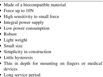
Table 1: Some important specifications of a prosthetic force sensor
• Made of a biocompatible material • Force up to 10N
• High sensitivity to small force • Integral power supply • Low power consumption • Robust
• Light weight • Small size
• Simplicity in construction • Little hysteresis
• Thin in depth for mounting on fingers or medical
devices
• Long service period
In biomedical engineering and medical robotics applications, tactile sensors can be used tosense a wide range of stimuli. This includes detecting the presence or absence of a grasped tissue/object or even mapping a complete tactile image[4-6].
Artificial palpation is another important application of tactile sensors. Additionally, tactile and visual sensing is of great importance in different types of surgeries. It has been demonstrated that automation
Author Manuscript
SCI-PUBLICATIONS
Author Manuscrip
technology can assist surgeons in minimal access treatment by enabling the benefits of steady tool motion through difficult access[7].
Minimal invasive surgery (MIS) is now being widely used as one of the most preferred choices for various types of operations[8-10]. MIS has many advantages, including reducing trauma, alleviating pain, requiring smaller incisions, faster recovery time, and reducing post-operation complications[11,12]. Applications to the prostatectomy procedure and in the resection of tumors in neurosurgery are excellent examples[13]. Other examples of advanced mechatronic surgical tools to enhance skill levels are in the alignments of bone tissues in craniofacial surgery[14], the control of cutting tools in knee surgery[15], the precise control of tool motion in soft tissues in the ear[16], and needle penetration[17]. However, MIS decreases the tactile sensory perception of the surgeon. In this situation, force and position signatures are the two factors that can provide a great deal of information about the state of gripping or manipulation of a biological tissue[18].
In order to take advantage of tactile sensing in applications that require imaging of force between two area surfaces, a versatile sensor technology is required. This technology should consider the spatial resolution, force sensing range, and sensing area size. A telesurgical system returns force sensation to the user corresponding with the reaction force of tissues to the tool action imposed. Figure 1 shows a function diagram of a master-slave system.
Fig.1: Function diagram of a master-slave system. The user inputs a tool action. This is sensed at the master system and is transmitted as a control demand to the tool operated by the slave system. The tool responds automatically by following the user input demand signal. The reaction force of the tissue is sensed at the
tool and is transmitted to the master system where actuators are applied to resist the motion of the input device. The control of tool motion in soft tissues requires careful monitoring of forces and responses. Such a system can be applied to scissors, forceps, needles, probes, and other tool actions.
The term tactile sensing covers a range of applications from object recognition by touch to measurement of the magnitude of the force over the area in contact with an object. For measuring a distribution of contact forces, resistive transducers have been investigated[19]. These are positioned such that there is significant deformation when subjected to a change in applied force resulting in a change in conductivity[20]. Piezoelectric sensors are alternative and are most suited to measuring fast transients and not steady levels[21]. Magnetic, mechanical, and optical transduction methods have also been used[22,23].
Capacitive sensor is a kind of sensor, which transforms non-electrical variety into capacitive variety. Comparing with other sensors, capacitance has some advantages, including high resolution, excellent accuracy, rapid dynamic response, consuming very little power, simple mechanism, and potential for low cost.
A suitable sensor for application in telesurgery and robotic surgery should determine the applied force and detect the force distribution and movement of surfaces by deformation. It should use operating media that do not present a risk to patients and it should be manufactured from biocompatible materials.
This paper introduces the design of a new type of capacitive tactile sensor and shows how to build rugged, reliable capacitive tactile sensor with high accuracy and low part cost. It can measure the magnitude and the position of an applied load on it. This sensor has good potential for use in surgical devices.
MATERIALS AND METHODS
A force sensor for using in robotic and manipulation tasks needs to be small, robust, low power, cheap, and easily controlled by using simple digital technique. We have designed and tested a new type of sensor which uses capacitive effects to measure the deflection of an elastic membrane, according to applying force on it. It can detect the 2D surface texture image and contact-force estimation.
Master System Operator
……… Surgeon
Tissue .…… Patient
Slave System
Central Tool
Force Demand Force
Contact Force
Author Manuscrip
2D Surface Texture Image Detection: This sensor can be used to sense a diverse range of stimuli ranging from detecting the presence or absence of a grasped object to a complete tactile image. Figure 2 shows an array of two elements of our tactile sensor. When the tactile sensor array comes in contact with an object that has a bumpy surface, some of the mesa structures on the membrane push inwards and as a result of it, the capacitance changes. Hence, the system can detect the presence or absence of object above each of the elements. Therefore, we can have a 2D surface texture image of the object.
Fig. 2: An array of two elements for detecting contact-force distribution and surface texture image.
Contact-Force Estimation: The structure of the
estimating contact-force is illustrated in Fig. 2. When the mesa of membrane comes in contact with an object, the normal force or uniform pressure from it causes inward deformation of the membrane. Therefore, by determining the displacement at the center of the membrane according to the capacitance change, we can measure the amount of normal force or the uniform pressure actuating on it.
Sensor Design: This sensor element is a pair of parallel plates which form a capacitor. One plate is glued to an elastic membrane which deforms in response to contact force. The other plate is attached to rigid substrate of the sensor. As the applying force changes, the membrane flexes and the distance between capacitor plates changes. The material of membrane should be elastic, highly stable, reliable, and with low hysteresis. The radius of membrane is 2 cm and it is attached on a rigid cylinder which has a port for exhaust. The thickness of membrane is 100 µm and the radius of mesa is 0.5cm with a thickness about 150 µm.
Table 2 shows typical specifications of the modeled sensor.
Table 2: Specifications of the modeled sensor Device(cylindrical) 2 cm (inner radius)
3 cm (outer radius) 1 cm (height)
Membrane 2 cm (radius)
100 m (thickness)
Mesa 0.5 cm (radius)
150 m (thickness)
Capacitor Plates(Al) 1 cm (radius)
100 m (thickness)
(Poisson’s ratio) 0.33
E (Elastic modulus) 30 MPa
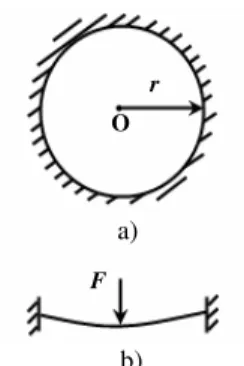
Mechanical Principle: The problem of axisymmetric
large deformation of circular membrane has practical significance. The theoretical model of a single-layer circular membrane is shown in Fig. 3.
Fig. 3: Theoretical model. a) Front view, b) Top view. For single-layer circular membranes under the concentrated force and by considering the large deformation theory of them, the solution for out-of-plane deflections (OPD) can be expressed as[24]:
2
1 3 4
3 1 / 3 3
( ) [1 ( ) ]
4
4 (1 )
d r F
h E h
ν
ν π −
= −
+
(1) if =1/3,
2 3 3
( )
4
d r F
h π E h
= (2) where d is out-of-plane deflection of membrane, r is radius of membrane, h is thickness of membrane, is Poisson's ratio, E is elastic modulus, and F is applied force at central point.
Electrical Principle: The capacitance between two
plates is determined by three parameters:
1.Size of the plates: Capacitance increases as the plate
F r
O
a)
b) Object
Mesa Membrane
Exhaust Plates
Contact No Contact
Author Manuscrip
size increases.
2.Gap size: Capacitance decreases as the gap increases. 3.Materials between the plates (the Dielectric): Dielectric material will cause the capacitance to increase or decrease, depending on the materials. Equation 3 shows the relationship between these parameters and the capacitance.
0 rA
c d
ε ε
= (3)
where c is the capacitance, 0 is the permittivity of free
space, r is the dielectric constant of the material in the
gap, A is the area of the plates, and d is their separation[25].
In this sensor, the surface of the plates and the dielectric material (air) remain constant. The only variable is the gap size. Based on this assumption, all changes in capacitance were produced as a result of a change in gap size. An integrated circuit in the transducer measures the capacitance and converts it to a frequency.
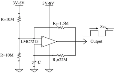
Figure 4 shows a schematic of our employed circuit for converting a change in capacitance into a signal[25]. One of our circuit advantages is that, if the frequency and the output current are being kept low, this circuit will operate with DC supplies below 1.5v.
Fig. 4: Oscillating circuit.
The above circuit oscillates with a frequency (f) given by the below equation:
] / ) ln[(
2
1
2 2
1 R R
R cR f
+
=
(4)
Experimental Method: In order to evaluate the
performance of proposed sensor, we have set one
experiment for determining the contact-force between the sensor and an object to find the relationship between the force and membrane deflection. In this test, a single tactile sensor was fabricated according to the theoretical model specifications. The material of membrane should yield sufficiently under low force, in an ideal elastic (no hystersis) and repeatable manner.
Several polymers were studied to identify one with suitable mechanical properties and more compatibility with the biological tissues. Materials with the high hystersis were rejected. We chose a particular kind of silicon rubber as the membrane and we made the body of the sensor out of PVC. In this work, according to the hardness of membrane, the maximum magnitude of applied force was limited to 1 N. There is a possibility for determining the higher force with choosing a material with higher hardness for membrane or changing the thickness of membrane. We stuck two thin plates of aluminum to the membrane and the substrate of sensor.
In this system, each of the components, including a probe, a driver, and an indicator, is a critical part in providing reliable, accurate device measurement. The probe geometry, sensing area size, and mechanical construction affect range, accuracy, and stability. A probe requires a driver to provide the changing electric field that is used to sense the capacitance. The electronic driver is a primary factor in determining the resolution of the system and must be well designed. We used a square wave oscillator (LMC7215) as a comparator in our system. The frequency measuring device is the final link in the system. A high resolution counter oscilloscope and data acquisition system selected for this task.
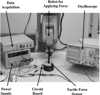
In our configuration, the change coming out via the oscillator represented the force applied to the membrane. A digital storage oscilloscope (Instek, GDS-820) and a high resolution counter (Victor) were used to measure the signal output from oscillator. Additionally, a data acquisition (AD Instruments, Power Lab-ML750) was used for collecting data and drawing the graph of output signal variation. The details of experimental setup are illustrated in Fig. 5. +
-3V-8V 3V-8V
Sec
R=10M R=10M
C R1=22M R2=1.5M
Output LMC7215
Author Manuscrip
Fig. 5: Photograph of the experimental setup.
Load tests: It should be noted that in tactile sensing, a force range of 0.1N to 10N is considered to have practical applications in medical devices[26-29]. Static forces were applied to the sensor in two ways. One way was using steel weights, in which loads were applied incrementally to nearly 1 N and then unloaded. The other way was using a robot hand and by applying a static force with a precise deflection on the membrane of the sensor.
RESULTS AND DISCUSSION
The theoretical and experimental results have been in good agreement. We investigated the deformation at the center of mesa and found that it changes with variations of applied force and the thickness of membrane. Figure 6 shows the variations of out-of-plane deflections of membrane with the constant radius and unique force (0.1N) at different thicknesses. Also, as a result of applied force at the center of membrane, we have an out-of-plane deflection on it. Figure 7 demonstrates the deformation or out-of-plane deflections of membrane according to the variations of applied force.
1.9 2.1 2.3 2.5 2.7 2.9
0.06 0.08 0.1 0.12 0.14
Thickness (mm)
D
ef
le
ct
io
n
(
m
m
)
Fig. 6: Variations of out-of-plane deflections vs. different thicknesses
2 2.5 3 3.5 4 4.5
0.1 0.2 0.3 0.4 0.5
Force (N)
D
ef
le
ct
io
n
(
m
m
)
Fig. 7: Variations of out-of-plane deflections vs. different applied forces
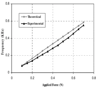
Static forces were applied to the sensor by using a robot hand with precise displacement and the output of circuit was recorded. Figure 8 shows the measured output frequency of the circuit versus the applied force to the membrane.
Robot for Applying Force Data
Acquisition
Power Supply
Circuit Board
Tactile Force Sensor
Oscilloscope
Author Manuscrip
0 0.2 0.4 0.6 0.8
0 0.2 0.4 0.6 0.8
Applied Force (N)
F
re
q
u
en
cy
(
K
H
z)
Theoretical
Experimental
Fig. 8: Output voltage vs. the applied force.
Although the equations 2, 3, and 4 show a linear relationship between the frequency and the applied force, Fig. 8 demonstrates that as the applied force increases, the frequency decreases in a nonlinear relationship. So, we can suggest a nonlinear regression model fitted to the achieved results.
CONCLUSION
Although a considerable number of sensor technologies and strong theoretical models have been developed, there is still much left to be done in intelligent grasping and manipulation. Also, there is a gap in applying the theoretical models in association with tactile sensing. We proposed a new type of tactile sensor that can detect the contact force. First, we analyzed theoretically the operation of sensor and secondly we constructed the sensor according to this analysis.
A major advantage of the designed system is that it can be easily miniaturized and micromachined. Because of the low mass, low size and low power characteristics of this sensor, it could be maintenance-free for a long period. These characteristics especially lead to opening up the possibility of putting more sensors, for example, in a prosthetic hand to improve functionality without a significant mass penalty. Also, small and simple electronic circuit allows using a simple interface as a
counter to a digital signal processor for measuring the output frequency. This sensor is made from robust and flexible biocompatible polymers that can be used to directly touch biological objects. According to its biological compatibility, the designed sensor has two main applications, one in MIS and one in artificial palpation.
ACKNOWLEDGEMENTS
This work was partially supported by the grant awarded by The Ministry of Health of Iran through Razi International Festival. The authors wish to thank The Ministry of Health for their support. We also would like to express our gratitude to the Center of Excellence of Biomedical Engineering of Iran based in Amirkabir University of technology, Faculty of Biomedical Engineering for its contribution.
REFERENCES
1. Lee, M.H., H.R. Nicholls, 1999. Tactile Sensing for Mechatronics–a State-of-the-Art Survey. Mechatronics, 9: 1-31.
2. Dargahi, J., S. Najarian, 2005. Advances in Tactile Sensors Design/Manufacturing and its Impact on Robotics Applications–A Review. Industrial Robot, 32: 268-281.
3. Howe, R.D., W.J. Peine, D.A. Kontarinis and J.S. Son, 1994. Remote Palpation Technology. Proc. IEEE Eng. Med. Biol. Mag.,14(3): 318-323. 4. Najarian, S., J. Dargahi and X.Z. Zheng, 2006. A
Novel Method in Measuring the Stiffness of Sensed Objects with Applications for Biomedical Robotic Systems. Int. J. Med. Robotics Comput. Assist. Sur., 2: 84-90.
5. Singh, H., J. Dargahi and R. Sedaghati, 2003. Experimental and Finite Element Analysis of an Endoscopic Tooth-Like Tactile Sensor. 2nd IEEE International Conference on Sensors, Toronto, Canada.
6. Dargahi, J., 2002. An Endoscopic and Robotic Tooth-Like Compliance and Roughness Tactile Sensor. J. Mech. Design, 124: 576-582.
7. Brett, P.N., R.S. Stone, 1997. A Technique for Measuring Contact Force Distribution in Minimally Invasive Surgical Procedures. Journal of Engineering in Medicine, 211: 309-316.
Author Manuscrip
8. Rao, N.P., J. Dargahi, M. Kahrizi and S. Prasad, 2003. Design and Fabrication of a Microtactile Sensor. Canadian Conference on Electrical and Computer Engineering Towards a Caring and Human Technology, Montreal, Canada.
9. Dargahi, J., S. Najarian, 2004. An Integrated Force-Position Tactile Sensor for Improving Diagnostic and Therapeutic Endoscopic Surgery. BioMed. Mater., 14: 151-166.
10. Dargahi, J., M. Parameswaran and S. Payandeh, 2000. A Micromachined Piezoelectric Tactile Sensor for an Endoscopic Grasper: Theory, Fabrication, and Experiments. J. Microelectromechan. Syst., 9: 329-335.
11. McGinty, J.B., S.S. Burkhart, R.W. Jackson, et al., 2002. Operative Arthroscopy. Lippincott Williams & Wilkins: Philidelphia.
12. Dargahi, J., S. Najarian, 2004. Analysis of a Membrane Type Polymeric-Based Tactile Sensor for Biomedical and Medical Robotic Applications. Sensors & Materials, 16: 25-41.
13. Weimin Shen Gu, J., E. Milios, 2004. Robotic Neurosurgery and Clinical Applications. Proc. Intelligent Mechatronics and Automation Int. Conf., 114-119.
14. Widmann, G., 2007. Image-Guided Surgery and Medical Robotics in the Cranial Area. Biomedical Imaging and Intervention Journal, 3.
15. Davies, B., K.L. Fan, R.D. Hibberd, M. Jakopec, S.J. Harris, 1997. A Mechatronic Based Robotic System for Knee Surgery. Intelligent Information Systems, 48-52.
16. Brett, P.N., B. Allotta, J. Wahrburg, V. Petridis, 1997. Research on Innovative Mechatronic Tools and Systems for Surgical Procedures Involving Soft Tissues. Proc. Mechatronics and Medicine Vision in Practice, Fourth Annual, 57-59.
17. Wakasa, Y., M. Oka, K. Tanaka, M. Fujii, S. Yamauchi, K. Minami, 2006. Development of a Needle-Insertion Robot for MRI-Guided Stereotactic Surgery. Journal of Robotics and Mechatronics, 18: 643-649.
18. Rininsland, H.H., 1993. Basics of Robotics and Manipulators in Endoscopic Surgery. Endoscop. Surg. Allied. Technol., 1: 154-159.
19. Mallin, J., 1989. Handbook of a Simple Sense of Touch for Robotic Fingers. Robotics Age, 24-27. 20. Fearing, R.S., 1990. Handbook of Tactile Sensing
Mechanisms. Int. J. Robotics Res., 9: 3-23.
21. Kolesar, E.S., R.R. Reston, D.G. Frod, R.C. Fitch, 1992. Handbook of Multiplexed Piezoelectric Polymer Tactile Sensor. J. Robotic Systems,9: 37-63.
22. Jenstrom, D.T., C. L. Chen, 1989. Handbook of a Fiber Optic Micro Bend Tactile Sensor. Sensors and Actuators, 20: 239-248.
23. Vranish, J.M., 1986. Handbook of a High Resolution Tactile Sensor. Robot Sensor, 2: 99-111.
24. Shan-lin, C., Z. Zhou-lian, 2003. Large Deformation of Circular Membrane under the Concentrated Force. Applied Mathematics and Mechanics, 24(1): 28-31.
25. Wilson, J.S., 2005. Sensor Technology Handbook. Elsevier, Newnes.
26. Dargahi, J., S. Najarian, 2004. An Endoscopic Force Position Grasper with Minimum Sensors. Canadian Journal of Electrical and Computer Engineering, 28: 151-161.
27. Dargahi, J., S. Najarian, B. Liu, 2007. Sensitivity Analysis of a Novel Tactile Probe for Measurement of Tissue Softness with Applications in Biomedical Robotics. Journal of Materials Processing Technology, 183: 176-182.
28. Mirbagheri, A., J. Dargahi, S. Najarian, F. Tabatabai Ghomshe, 2007. Design, Fabrication, and Testing of a Membrane Piezoelectric Tactile Sensor with Four Sensing Elements, American Journal of Applied Sciences, 4(9): 645-652. 29. Ramezanifard, R., J. Dargahi, S. Najarian, F.
Tabatabai Ghomshe, 2007. A Novel Modeling Approach for Collision Avoidance in Robotic Surgery, American Journal of Applied Sciences, 4(9): 693-699.