ISSN 1549-3636
© 2010 Science Publications
Corresponding Author: Bakri Ali, Department of Humanoid Robot and Bio-Sensor, Faculty of Mechanical Engineering, University Technology MARA, (13500), Permatang Pauh, Pulau Pinang, Malaysia
A New Approach in Design and Operating Principle of Silicone Tactile Sensor
Bakri Ali, Rozaini Othman, Rasdi Deraman and Muhammad Azmi Ayub
Department of Humanoid Robot and Bio-Sensor, Faculty of Mechanical Engineering,
University Technology MARA,
(13500), Permatang Pauh, Pulau Pinang, Malaysia
Abstract: Problem statement: Research and development in tactile sensor are escalating due to the fact that advanced robot needs to interact with surrounding environments which is very complex, dynamic, uncontrolled and difficult to perceive reliably. Recent research has been focusing in development of new tactile sensor that takes advantage of advances in materials, Micro-Electromechanical Systems (MEMS) and semiconductor technology. To date, several basic sensing principles are commonly used in tactile sensor such as capacitive sensor, piezoelectric sensor, inductive sensor, opto-electrical and piezo-resistive sensor. However they are still lack of sensitivity and low dynamic range in sensing the changes of forces in 3 axes and not durable enough to perform in various working environments. Approach: Three different designs of optical tactile sensor was proposed and analyzed. The overall design of the test-rig of the system was presented. The working principle was based on the deformation of the silicone tactile sensor. The deformation image will be transferred through high quality medical fiberscope and will be recorded using a CCD camera. The image will be stored in a computer for further analysis to relate the image with the given forces. These data can be used to control a robotic gripper so that it can perform gently and precisely like human tactile sensing capability but with greater strength and durability in various working environments. Results: The sensor had been designed and an experimental test rig was developed. Initial experiment was carried out to check the potential of this technique. Based on results, there is almost a linear relationship between the forces and the deformation of the tactile sensor. The amount of deformation is calculated based on the analyzed image data. Conclusion: The results of the experiment gave a convincing idea and provide a ground for further research to enhance this system to be an alternative tactile sensor in future.
Key words: Tactile sensor, image processing, silicone, deformation
INTRODUCTION
Robotic grippers and manipulators are widely used all over the world to perform various tasks especially in industrial application for repetitive and dangerous working atmosphere. Robot interactions with surrounding environments present special challenge since they are complex, dynamic, uncontrolled and difficult to perceive reliably. Hence, skills and active sensing system needed by a robot to realize contact sense with environments. However most of the grippers used to date are of the passive gripper, which means that they are operated based on constant gripping force. The use of passive gripper is therefore limited to be used to handle hard objects and the gripping force need to be reprogrammed if the different object of different hardness need to be handled. With the advancement in robotic research, more and more capability of robot is
developed to perform various tasks that need manipulation skills such as in medical operation, humanoid robots and household work. The range of object hardness also changes instantly while the robot performing its duty. These applications need an active gripper, which can react to the variable force or pressure just like the humans tactile sensing capability. As convincingly demonstrates by a blind people, tactile sensing alone can support extremely sophisticated manipulation.
tactile sensor consists of a photo reflector covered by urethane foam and organized as a network of self-contained module that communicates through a serial bus. A research team at Nagoya University developed a novel optical three axes tactile sensor system based on an optical waveguide transduction method capable of acquiring normal and shear force (Ohka et al., 2004). Fath El Bab et al. (2009) uses information from a micro-machined piezoresistive type tactile sensor to detect the compliance (reciprocal of stiffness) of a soft tissue in order to help the surgeon to determine the health of a tissue. Petropoulos et al. (2009) fabricated a capacitive type tactile sensor using copper clad laminated with flexible polyimide substrates (Kapton). Polster and Hoffmann (2009) proposed a tactile sensor based on tridimensional piezoelectric Aluminum Nitride (AIN) membranes. By analyzing strengths and weaknesses of the above mentioned researches, a new tactile sensor based on a silicone material combined with image analysis technique was proposed in this study.
MATERIALSANDMETHODS
Silicone rubber: Silicon rubbers are polymers having the alternate atoms of silicon and oxygen known as Silica (SiO2) in the main chain with organic side groups attached to the silicone atoms (Bhat, 2005). Medium and hard grades silicones are made from dimethyl-siloxene copolymerized with small amount of methylvinyl-siloxane. Softer grades are made from copolymer of dimethylchlorosilane and methylvinyl-siloxane containing small amount of phenyl-methyl-siloxane which gives the softness attributes to the mixture. The physical properties of silicone rubbers depend upon the composition and conditions of the curing procedures. Silicon is a very stable material and widely used in mocking the human body parts especially in plastic surgery. As such this material is suitable to be used for the proposed tactile sensor. One major limitation of silicone rubber is poor resistance to tearing.
Sensor design: The working principle of this sensor is based on the deformation of the silicon material. The deformation image is transmitted by the fiber scope to the machine vision system for further analysis in order to find out the magnitude and the direction of the applied force on the silicon material. Three designs have been proposed for the sensor as shown in Fig. 1. The proposed design is in hemispherical shape resembles the end of the human finger. The smaller area (diameter) at the finger tip will allows the gripper to deform at the minimum force while the bigger diameter to the end will be able to withstand a bigger force. Curved surface can tell the robot the direction of the forces acting on it and the robot will react accordingly to adjust the arm movement. To select the most suitable design, a finite element analysis is carried out for the virtual checking of the deformation based on the recommended force which is around 0.4-10 N (Crowder, 1998).
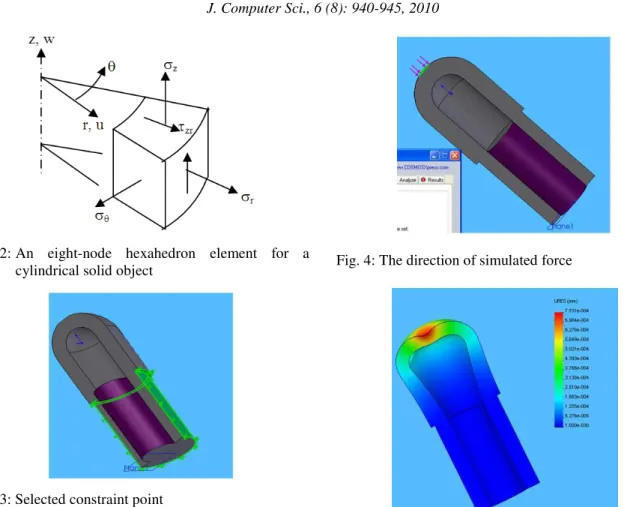
Design A has a uniform shell thickness on the hemispherical dome. For this simulation, it is taken as 3 mm. Design B has a 2 mm uniform thickness for the dome but a taper below is designed to accommodate the view angle of the fiberscope. Design C given a flat internal surface to withstand greater force. The external dimension of all the proposed design is identical. The sensor designed is a 3D solid produced by revolution of a 2D shape. This means that there will be 3 possible normal stresses and 3 shear stresses must be considered. The tetrahedral and hexahedra mesh is the most suitable mesh for 3D solid (Cook, 1995). For a cylindrical solid, each element is expressed in the cylindrical coordinate as shown in Fig. 2.
If deformation are axially symmetric (axisymmetric), the circumferential displacement component is zero. The radial displacement component, u = u(r, z) and the axial displacement component is w = w(r, z). Shear strains γrθ and γθz are zero. The non-zero strains are:
r
z yz
u / r u / r
w / z ( w / z) ( u / r ) θ
ε = ∂ ∂ ε =
Fig. 2: An eight-node hexahedron element for a cylindrical solid object
Fig. 3: Selected constraint point
Displacements within the elements, u can be interpreted from the nodal degree of freedom (d.o.f) d whereby u = Nd, where N is the shape function matrix. If nodes has only translational d.o.f and n is the number of nodes per element, N has 2n columns for an axisymmetric element. Thus, u = Nd is:
1
1
1 2 2
1 2 2
u w
u N 0 N 0... u
w 0 N 0 N ... w
. .
=
(2)
The sensor is designed using solid works and analysis is done using COSMOSxpress study software which is embedded in solid works. Limitation of this software is the material properties cannot be set. It is automatically assigned by selecting the material we use (in this case, silicon). For better observation, only half of the silicon tactile sensor is modeled so that we can see clearly the deflection and stress across the cross section. Constraint point is set on the circumference whereby the fiberscope lens (distal end) is clamped as shown in Fig. 3.
Fig. 4: The direction of simulated force
Fig. 5: Deformation due to 10 N force on design B
Fig. 6: Simulation result for proposed design
Force is simulated on the centre of the hemispherical cone at various magnitudes from 0-10 N in the direction as shown in Fig. 4. Simulation image is shown in Fig. 5 and 6 shows the graph for comparison between these three designs.
(but still in safe mode) which will enable the camera to detect a small changes of the force. This result also shows that it is better to provide the gridlines on the top surface rather than on the internal surface of the sensor since the deflection is higher and can be easily detected. However, sharpness of the image might be less since the light has to travel into the silicone substrate. Based on this simulation results, the design B have been selected for experimental purpose with the grid is provides inside the silicone hemisphere.
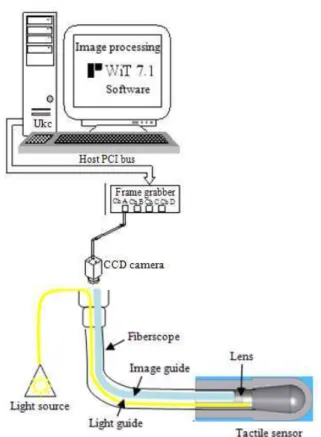
Fiberscope: A High quality Olympus Industrial Fiberscope is used as the image transmission. The eyepiece is attached to a CCD camera and an acquired image is stored in a computer for analysis. The image is transmitted through a high density flexible fiberglass cable for best image transmission. External light source is supplied into the gripper hemisphere using a light guide cord for bright and sharp images. A complete schematic arrangement of image acquisition system and Fiberscope is shown in Fig. 7.
Test rig: The test rig consists of a sturdy bracket to avoid any relative movement between the applied deflection and the tactile sensor thus reduces the error. A bracket constructed from an aluminum alloy bar and bolted to form the required bracket. A high quality Olympus medical fiberscope is inserted inside the tactile sensor to transmit a high quality image to a Charge Coupled Devices camera (CCD camera) which fixed at the end of eye-piece to record the deformation image of the silicon tactile sensor. A micrometer is used to give a deformation to the tactile sensor. The micrometer will be clamped in front of the tactile sensor on the same sturdy base as shown in Fig. 8. The image is then sends to a computer for storing and displayed on the screen. The detail cross section inside the sensor shown in Fig. 9.
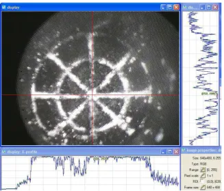
Method: A micrometer dial is advanced until it nearly touches the tactile sensor. The reading is set to 0 mm and a reference image is taken as shown in Fig. 10.
Fig. 7: Schematic arrangement of image acquisition system and fiberscope
Fig. 8: Test rig assembly
Fig. 10: Captured reference image
Fig. 11: Image at 4 mm displacement
The position of 3 points (P1, P2 and P3) along the grid is recorded in terms of pixels distance in x and y axes. The micrometer dial is then advanced in every 0.5 until 4 mm reading where the image becomes badly distorted. Figure 11 shows the position of the points at 4 mm displacement. The complete result is tabulated in Table 1. Using PYTHAGORAS theorem the radius between P1 and P2 (R1) and between P1 and P3 (R2) are calculated and the results shown in Table 2. The values of R1 and R2 are determined using the formula as follows:
(
) (
2)
21 2 1 2 1
R = x −x + y −y
(
) (
2)
22 3 1 3 1
R = x −x + y −y
Fig. 12: Radius versus displacement
Table 1: Position of reference point at given displacement Point 1 (P1) Point 2 (P2) Point 3 (P3) Displacement --- --- ---
(mm) x1 y1 x2 y2 x3 y3
0.00 326 298 452 298 536 291
0.50 338 310 464 307 545 298
1.00 324 302 457 300 539 291
1.50 312 317 452 310 530 298
2.00 311 332 457 317 533 303
2.50 310 341 462 322 538 306
3.00 300 341 463 313 534 290
3.50 283 323 451 285 527 264
4.00 250 290 439 243 514 226
Table 2: Radius between points at given displacement
Displacement (mm) R1 (pixels) R2 (Pixels)
0.00 126.00 210.12
0.50 126.04 207.35
1.00 133.02 215.28
1.50 140.17 218.83
2.00 146.77 223.89
2.50 153.18 230.67
3.00 165.39 239.49
3.50 172.24 251.03
4.00 194.76 271.65
A graph is plotted based on Table 2 to show the relationships between the radiuses of each point versus the displacement given by micrometer as shown in Fig. 12.
RESULTS AND DISCUSSION
experiment give a convincing idea for future works and provide a ground for further research to enhance this system to be an alternative tactile sensor in future.
ACKNOWLEDGMENT
The researchers would like to convey an appreciation to University Technology MARA Malaysia for giving the grant and scholarship in this research project. Special thanks to all parties involved which enables this study to be written.
REFERENCES
Bhat, S.V., 2005. Biomaterials. 2nd Edn., Alpha Science International Ltd., Oxford, ISBN: 10: 1842652079, pp: 294.
Cook, R.D., 1995. Finite Element Modeling For Stress Analysis. 1st Edn., Wiley, New York, ISBN: 10: 0471107743, pp: 336.
axis tactile sensor under combined loading.
Robotica, 22: 213-221. DOI:
10.1017/S0263574703005538
Petropoulos, A., G. Kaltsas, D. Goustouridis and E. Gogolides, 2009. A flexible capacitive device for pressure and tactile sensing. Proc. Chem., 1: 867-870. DOI: 10.1016/j.proche.2009.07.216
Polster, T. and M. Hoffmann, 2009. Aluminum nitride based 3D, piezoelectric, tactile sensor. Proc.
Chem., 1: 144-147. DOI: