ISSN 1546-9239
© 2007 Science Publications
Corresponding Author: Ari Legowo, Department of Mechanical Engineering, Faculty of Engineering, International Islamic University Malaysia, P.O. Box 10, 50728 Kuala Lumpur, Malaysia
Robust Flight Control Design for a Turn Coordination System
with Parameter Uncertainties
1Ari Legowo and 2Hiroshi Okubo
1Department of Mechanical Engineering, Faculty of Engineering
International Islamic University Malaysia, P.O. Box 10, 50728 Kuala Lumpur, Malaysia
2Department of Aerospace Engineering, Osaka Prefecture University
Gakuen-cho 1-1, Sakai, Japan
Abstract: This paper presents a method of robust control system design for aircraft flight control systems with the existence of uncertainty parameters such as stability and control derivatives resulted by parameter identification process using real flight test data. A nonlinear model of aircraft turn coordination system is considered where the problem is to find the optimal controller by using the H∞
optimal control method combined with a quasi-Newton optimization method. The present method designs the gain of the cross pass channel for the aileron and rudder interconnect, which causes nonlinearity of the system. The robust controller design is qualified as designing the H∞ optimal
control under a given value of the ‘nonlinear’ gain, and sequentially determining the optimal ‘nonlinear’ gain subject to minimize the error performance of the turn coordination system by using the quasi-Newton method. The perturbations of the uncertainties model have structured uncertainties constructed by the differences between the aerodynamic coefficients derived by parameter identification process and wind tunnel result. The proposed method is applied to the real flight test data of N250 PA-1 aircraft.
Key words: Flight Control System, Turn Coordination System, Optimization, Robust Control
INTRODUCTION
The purpose of the design of the flight control system for the turn coordination system of an aircraft is to design control laws that determine controller such that the augmented system will allow roll command to perform steady bank angle while keep the lateral acceleration and yawing moment small. For a modern aircraft, the effect of yaw angle due to aileron deflection is adverse and cannot be neglected. It can be analyzed in control derivative
A
n
C
δ , the rate of change
of yawing moment coefficient with aileron deflection, is more than 10% of the rate of change of rolling moment coefficient with aileron deflection
A
l
C
δ . In
designing of an automatic control system, a cross pass channel from aileron command to rudder is necessary for minimizing effort on feed-back input of rudder to counter the effect of adverse yaw. This channel is called as aileron rudder interconnects (ARI), which purposes to provide the component of yaw rate necessary to achieve a stability-axis roll.
The robust system model of turn coordination includes the linear model of aircraft lateral/directional modes, actuators model, parameter uncertainties in aerodynamics, and the controller is linear and time invariant. However, the existence of the cross pass channel ARI causes nonlinearity to the closed loop of turn coordination system, and it makes the design of the optimal ARI gain and other controllers more complex. In order to determine the optimal gain of a robust control system, application of H∞ optimal control
method is most familiar. This method addresses the design of stability and sensitivity produces a stable closed loop system, but it requires a direct one-step procedure. This paper proposes an iterative algorithm to determine the controller by using the H∞ optimal
control method. It uses a quasi-Newton optimization to optimize the value of ARI gain subject to minimize the sensitivity matrix of the closed loop system.
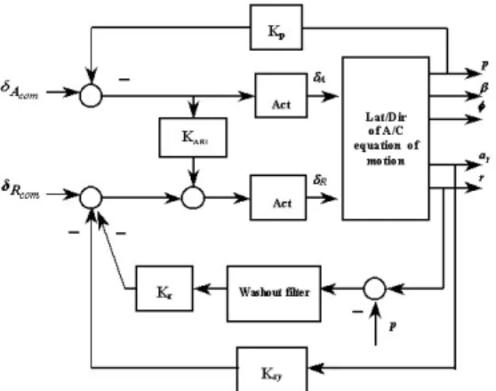
Fig. 1: Block Diagram of Turn Coordination System.
NOMINAL MODEL FOR NONLINEAR FLIGHT CONTROL
Consider the nominal model of an aircraft turn coordination system as shown in block diagram in Figure 1. The model of aircraft lateral/directional dynamics is linearized by using the small perturbation technique, and a linear model suitable for control law design, is obtained as follows:
Cx y Bu Ax x o = + = (1) where x = [β p r φ]T , u = [δA δR]T, yo = [φ β p ray]T
are state, input and observation vectors, respectively, and matrices A and B are
= 0 ) tan( 1 0 0 N N N 0 L L L ) gcos( Y Y Y * r * p * v * r * p * v * r * p * v θ θ
A (1a)
= 0 0 N N L L Y Y * δ * δ * δ * δ * δ * δ R A R A R A
B (1b)
The Output feed-back control is applied in the closed loop system, where it takes the measurement of roll rate as the element feed-back for aileron command and takes the lateral acceleration combined with difference between yaw rate and roll rate as the element feed-back for rudder command. To reduce the contribution of the element feed-back for rudder on countering adverse yaw effect, feed-forward gain of the cross pass channel ARI (KARI) is engaged.
The actuator models for the aileron and rudder are assumed as first order transfer functions with time
constant of 0.1 second. A low pass filter or washout filter model is put on the feed-back channel of yaw and roll rate for rudder input, and it has a first order model with time constant of 0.25 second.
ROBUST MODEL FOR PARAMETER UNCERTAINTY
Since the value of the ARI gain is not known, or it will be determined, the nominal turn coordination system illustrated by Figure 1 is nonlinear. Because the input element of rudder is also contaminated by the aileron input, the input matrix B is not a constant matrix anymore.
In order to utilize the method of H∞ optimal
control, it is assumed that the value of ARI gain is given and the input matrix B is written in the form
= ∗ 1 0 K 1 ARI B
B (2)
The block diagram of augmented robust system of turn coordination with uncertainty is shown in Figure 2 where the model of augmented system is given by
u D w D x C y u D w D x C z u B w B Ax x 22 21 2 12 11 1 2 1 + + = + + = + + = (3)
where z and w are output error and plant’s disturbance, respectively, and the input matrix B2 = B*. Then matrix model of disturbance to state B1, matrices C1, D11, D12 mentions the output control model, matrix C2 explains the output control model, matrix D21 contains elements that represents a relationship between output control and disturbances, are more detailed by next equations, while matrix D11 = 0 and also matrix D22 = 0. In this model, it is assumed that the perturbations are included only in the plant and caused by the uncertainty in the coefficients of aerodynamics.
The robustness to parameter uncertainties is accomplished by modeling the uncertainties in the aerodynamic coefficients as perturbations of the nominal model. Where the uncertainties model is defined as the nominal turn coordination system (Eq. 1) plus uncertainty in the aerodynamic and control derivatives contained in the matrices A and B. The uncertainty is a structured uncertainty ∆AB defined as
yu 1
AB B ∆∆
∆ = (4)
where ∆AB =[∆A∆B] is uncertainty in the
aerodynamic coefficients corresponding to the elements of matrices A and B, and matrix∆represents the difference between aerodynamic coefficients resulted by wind tunnel test and those obtained from parameter identification process, and has term as follows:
r p β R δ A δ r p
β y y y y l l l
y
diag[∆{C C C C C C C C
= ∆ }] C C C C C C C R δ A δ r p β R δ A
δ l n n n n n
l
(5)
where ∆Cy••= (Cy••)FT - (Cy••)WT , etc., and matrix∆yu is an output model of uncertainties.
The Plant perturbation w is defined as
T R
A δ ]
δ
[ com com ∆
= δ
w (6)
where
com
A
δ and δ
com
R are the roll and yaw rate commands to the aileron and rudder, respectively, and
∆
δ is perturbation of ∆AB that satisfies δ∆ ∞ ≤1.
The output error to be kept small in face of perturbation is the error between an ideal model of aircraft response and output resulted by the closed loop system. In the present system, the bank angle responses, on steady state of turn, to aileron deflection and sideslip angle are taken as the ideal models:
A L δ 2 1 K C K -C A δ l
φ= (7)
β φ 3 1 K C K L = where β β r r r β r β β β r β r β l n l n l n n l n y n l l y C C C C K C C C K ) C C (C -) C C (C K 3 2 1 C = − = − = + + = k k k µ µ 4 4 (7a)
And also the ideal model of the estimated adverse yawing moment due to the rolling wing is given by
V L 2 w b 8 C
-Cn= p (8)
where bw is wing span
Let note the ideal model output in Eqs. 7 and 8 as ideal
φ for bank angle and idealr for yaw rate, where the idealr is determined by integrating the yawing coefficient in Eq. 7. Then the output error model for robust turn coordination system can be denoted as a matrix: − − = r r φ
φ
ideal idealz (9)
The output to be fedback is
T ]
[p r-p ay
=
y (10)
and the gain to be achieved corresponding to this output control has a structure as follows:
= y a K K 0 0 0 K r p
K (11)
OPTIMIZATION METHOD
The method of H∞ optimal control is used for
designing robust control, where the control law is assumed to be an output feed-back having a constant gain matrix K:
Ky
u= (12)
Thus, the augmented closed-loop system of Eq. 3 including the output feed-back control law in Eq. 12 is
21 12 11 c 2 12 1 c 21 2 1 c 2 2 c KD D D D KC D C C KD B B B KC B A A + = + = + = + = (13a)
where it is assumed that D22 =0. Then, this optimization is subjected to minimize the singular values of the transfer function Gzw ∞.
For computing H∞ norm of the closed loop
system in Eq. 13, consider the following fact that1) γ
< ∞
zw
G if and only if the right spectral factorization of Hamiltonian matrix
+ − + − + − − − − T T 1 T 1 T T 1 T 1 ) C D R B (A )C D R D (I C B R B C D R B A c c c c c c c c c c c c c
c (14)
has no imaginary eigenvalues, where
0 D D I
R=γ2 − c cT > . (15) As a consequence of the implementation facts above, if the perturbations matrix in Eq. 6 is under scaled to be less than one, then K is representation of an optimal controller of the augmented closed loop system. In order to determine the optimum gain K, a quasi-Newton method is employed taking at its advantage and it can be formulated as a recursive algorithm2):
) ( ). ( ) ( ˆ ) (
ˆ i i i i
f
f G
H K
K +1 = − −1 (16) where
T ARI a r
p K K K ]
[K ˆ
y =
K (17)
(i) and
(i) f
f H
G are first derivative and second
derivative of the cost function f with respect to Kˆ
corresponding to iteration number i, respectively. The cost function to be minimized is given by
∞ = Gzw ) ˆ (K
f (18) The existence of the optimal solution of matrix Kˆ is depending on the given initial values, continuity of Gf,
and invertibility of Hf.
NUMERICAL SIMULATION
The present design method is examined for a turboprop N250 PA-1 aircraft, which is being produced by Indonesia Aircraft Industries. The model of turn coordination in Eq. 3 is taking for 150 Knots on airspeed trim 10,000 feet altitude on cruise flight condition. The parameter uncertainties are contained in the differences between the parameters resulted from wind tunnel test and from aerodynamic parameter identification test4),5).
The initial value of the aileron rudder interconnect gain can be determined by using the data of rudder-aileron deflections ratio on trim condition and utilizing the stability and control derivatives data determined from wind tunnel test result depending on the aircraft trim speed and angle of attack3). For the N250 PA-1 aircraft, the initial value of ARI gain have been modeled as a linear form as follows6)
KARI= 0.0212α – 0.3858 or
KARI = -0.0021VE + 0.1260 (19) where α is angle of attack in degrees and VE is
equivalent airspeed in knots. The other initial values of the gain matrix in Eq. 11 are also determined by using the stability and control derivatives of trim data collected by the flight test data engineering report6).
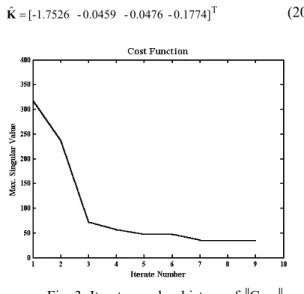
By solving the recursive equation in Eq. 16, the optimum gain Kˆhas been determined as follows:
T 0.1774] 0.0476 0.0459 [-1.7526 ˆ =
K (20)
Fig.4: Step Aileron Responses.
Fig.5: Singular values of transfer function Gzw ∞.
Fig. 6: Singular values of transfer function Gzw ∞for system with full state feed-back.
It can be shown that, the result of the optimal KARI above is close enough to the predicted value of KARI corresponding to trim speed of 150 Knots as given by Eq. 19. The cost function history by iteration number is shown in Figure 3. Figure 4 shows the step aileron responses of roll angle and yaw-rate for the condition of the ideal model and the designed closed-loop system. The yaw-rate response of the ideal model is derived from Eq. 8 and it is assumed that the coefficient of yawing moment has a linear combination of its derivatives. It shows that the designed closed-loop responses are good in tracking the ideal model and the outputs error converges to zero. The plots of singular values, with given disturbance on aileron command, are shown in Fig. 5. The robustness is indicated well for yaw-rate response to the parameter uncertainties entire the frequency range. On the other hand, the robustness for roll response is good in the high frequency range, but not good enough in the low frequency range. It also indicates that some of disturbances of parameter uncertainties resulted by flight test reject the robustness characteristics. The other possibility is that the single contribution of the element feed-back for roll command is not sufficient for handling the turn coordination problem, and it needs some additional information for the element feed-back, i.e., yaw-rate or sideslip angle. This reason is supported by a numerical simulation of the full state feed-back system for turn coordination. In this case, the robustness for roll response is good in the entire frequency range, see Fig. 6.
CONCLUSION
A method of robust control design has been developed for aircraft flight control in turn coordination system including parameter uncertainties in aerodynamics. The control laws have been designed by using H∞ optimal control method and taking advantage
of quasi-Newton optimization for optimizing the ARI (aileron rudder interconnect) gain.
The results of numerical simulations show that the proposed method is satisfactory regarding robustness of performance and control. The proposed method has a potential for application to other robust control problems.
REFERENCES
2. Polak, E., 1997. Optimization. Algorithms and Consistent Approximations, Springer -Verlag, New York,
3. Stevens, B.L and Lewis, F.L. 1992. Aircraft Control and Simulation, John Wiley & Sons, New York
4. Legowo, A., Okubo, H., Muramatsu, E., and Tokutake, H. 2001, One-Step Parameter Identification Using Moving Horizon States Estimation Method, Preceedings of 15th IFAC Symposium on Automatic Control in Aerospace, Bologna-Italy, 265-269.
5. Legowo, A., Okubo, H., Muramatsu, E., and Tokutake, H. 2001. Application of Moving Horizon Method to States Estimation from Flight Test Data, Trans Japan Soc. Aero. Space Sci. Vol. 44, No 145, 150-154.
6. Indonesia Aircraft Industries, Division of Flight Test Center, Flight Test Data Engineering Group: N250 PA-1 Flight Testing Data on Aerodynamics Parameter Identification, 1996.