Abstract—We look at the problem of real-time tumor tracking and motion compensation in radiotherapy techniques from a pure feedback-control point of view and try to understand it using simple mechanical models of the treatment couch and breathing patterns. Since we want to control a robotic couch based on the data collected in real-time, we propose the use of an acceleration sensor to develop a feedback control system to correct for the random movements of the tumor. An acceleration sensor offers a much richer set of data and in situations of rapid change in the breathing pattern, an acceleration sensor can provide a quick measurement and prediction of the trend. Our simplified models and the prototype show stable response under normal conditions.
Index Terms— Acceleration sensor, automatic couch, cancer, engineering design, feedback control, innovation, mathematical modeling.
I. INTRODUCTION
According to the American Cancer Society [1], Cancer is the second most common cause of death in US (after heart attack) with over one million people getting cancer each year. Out of all types, lung Cancer is the most frequent form of Cancer. Hence developing technologies for the accurate treatment of lung cancer is of paramount importance for health sciences. Cancer develops when cells in a part of the body begin to grow out of control. The root cause of this is a defect in the gene structure of the cell [2], [3]. When that happens, generally a tumor is formed.
A tumor can be of two types, benign or malignant. Benign tumors can generally be removed and do not spread to other parts of the body. On the other hand, malignant tumors grow rapidly and may travel to the other parts of the body via blood circulation and hence must be cured early. The process of Manuscript received July 21, 2008. This work is supported in part by funding from Tec de Monterrey and the GIRATE research group.
M. A. Yousuf is a member of the GIRATE research group and works with the Department of Mechatronics, Tec de Monterrey, Santa Fe Campus. Avenida Carlos Lazo 100, Colonia Santa Fe, Delegacion Alvaro Obregon, CP 01389, Mexico DF.; e-mail: [email protected]).
P. C. Rivera is a BE student at Tec de Monterrey, Department of Mechatronics, Avenida Carlos Lazo 100, Colonia Santa Fe, Delegacion Alvaro Obregon, CP 01389, Mexico DF (e-mail: [email protected]).
M. P. Diaz is a member of the GIRATE research group and works with the Department of Mechatronics, Tec de Monterrey, Santa Fe Campus, Avenida Carlos Lazo 100, Colonia Santa Fe, Delegacion Alvaro Obregon, CP 01389, Mexico DF (e-mail: [email protected]).
R. Montufar-Chaveznava is a member of the GIRATE research group and works with the Department of Electronics, Tec de Monterrey, Santa Fe Campus, Avenida Carlos Lazo 100, Colonia Santa Fe, Delegacion Alvaro Obregon, CP 01389, Mexico DF (e-mail: [email protected]).
cancer spreading is called metastasis. Depending upon the tumor location and extent, a surgical removal, chemotherapy, or a radiation therapy may be recommended for treatment [4]. Various other methods are available for this purpose too including direct surgery and minimally-invasive surgery. A combination of these has also been used. We are currently interested in variants of radiotherapy [5].
The plan of the paper is as follows. In section II we provide a literature review with a focus on works that follow a similar approach. In section III we discuss the details of the problem of tumor localization and our approach to it. In sections IV and V we discuss the mathematical models of the lung-tumor system and breathing. The next, section VI details our experimental setup. We conclude with some results and comment on future directions in section VII.
II. LITERATURE REVIEW
Different groups have tried various approaches to follow the tumor movement, using a mixture of experimental measurements and some sort of mathematical modeling [6], [7]. The main problems in this process are:
a. The lung tumor itself is not visible from outside hence direct image processing methodologies are not effective.
b. The scanning methodologies (like CT scan) put restrictions on the number of times they can be applied to the same patient in the same session due to the use of radiations.
c. A surface monitoring of the chest provides only an ‘estimate’ of the tumor position
d. Mathematical / Statistical models of the human body are approximations and generally require extensive computations.
e. Even if all the above problems can be solved, we still need extremely fast electronics to cope with the actual control of treatment couch which has its own dynamics.
f. We also have take into account inherent latencies in the mechanical and electrical systems (drives, servo systems, MCU clock speeds, etc.)
Figure 1: A simplified model of a lung. The air flows in and out from the right hand side.
investigated [10], [11]. These rely on infrared tracking and synchronized x-ray imaging to locate the tumor. Finite state models for respiratory motion analysis in image guided radiotherapy have been explored and provide a tool to quantify respiratory motion characteristics [12]. Low et. al. [13] have developed a mathematical model for the lung tumor movement based on five degrees of freedom, including the tidal volume rate of change. This variable plays an important role in the simple mathematical model we have presented in this paper. For the purpose of this paper we follow the approach taken by the D’Souza, et. al. [14], [15]. They suggest the use of a robotic treatment couch whose position can be adjusted using position markers on the chest. Sohn., et.al. [16] model the respiratory system using the Weibel’s morphometry [17] and show that the average velocity of exhaust is always greater than that of the inhale during tidal breathing, provided the intervals of inhale and exhale are identical.
Another important reference is that of Nakao, et.al. [18] and their approach is quite similar to the current methodology, though at a much more sophisticated level. They propose methods for radiotherapy planning for dynamic tumor-tracking for lung tumors. Their mathematical model treats the lung as an elastic object and uses the Finite Element Method to study the deformation of the lung. The paper [19] develops a model and prediction of lung tumor motion for a new adaptive tumor tracking system in radiotherapy.
III. DETAILS
In order to solve this problem with the available resources we had to make various approximations and adjustments in our proposed design. We first discuss the “ideal” solution and then, one by one we’ll show how to approximate the problem to a more tractable level where simple microcontrollers can be used to control the system autonomously.
Ideally, the couch should have (controllable) six degrees of freedom (three translations and three rotations which can be taken as the roll, yaw and pitch). The patient (and his tumor) can also have any of the previously mentioned movements. Part of these movements (the breathing cycle) can be approximated as a sinusoidal movement for a small period of time t. After that time, either the breathing pattern breaks due to normal human behavior or due any other unexpected circumstance (sudden jerk in the body, reflex action, vibrations, etc). Hence a six degree of freedom system (the
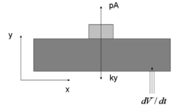
Figure 2: A rectangular model of the lung tumor system
patient) has to be compensated by another six degree of freedom robotic couch. If are the unit vectors of the unperturbed system are
i, j, k
and the unit vectors of the rotated system arei', j', k'
; andl l l
x, ,
y zare the translations in the three coordinate axis, then the 4x4 representation of the transformation equation can be written as:0
0
0
1
x y z
l
l
l
⎡
⎤
⎢
⎥
⎢
⎥
⎢
⎥
⎢
⎥
⎣
⎦
i.i'
j.i'
k.i'
i.j'
j.j'
k.j'
i.k'
j.k' k.k'
(Each of the dot products written above can also be written as sine or cosine of the angle between the two axes. We prefer to leave them in the above form for simplicity). However, if we look at the problem closely, some of the degrees of freedom are really not necessary and one can look for approximations. First, the translational movement along z-axis (perpendicular to the base frame, or in the vertical direction of the room) can be eliminated as the beam energy will remain more or less the same even if the height changes. Hence we can eliminate one degree. Also note that the beam is circularly symmetric and hence rotation along z-axis is also unnecessary.
We are therefore left with 4-degrees of freedom. Out of these, the two rotations along x- and y-axis may also be ignored as a first approximation as that would mean the beam falling at an angle on the tumor. Part of this can be compensated for by movements along x and/ or y-axis as the ultimate objective is to keep the tumor directly under the beam (the beam must be switched off when it is off tumor). Although these two dimensions will be important at a more advanced level due to the non-spherical nature of the tumor where the bottom may need different treatment, we ignore them for now. Hence we are finally left with only two translations along x- and y-axis which need to be controlled and the transformation matrix becomes:
0 0 0 0 0 0
0 0 0 0
0 0 0 1
x y l
l
⎡ ⎤
⎢ ⎥
⎢ ⎥
⎢ ⎥
⎢ ⎥
⎣ ⎦
The second part of the project is simulating the breathing of a patient. For that we have developed a small doll fitted with a servo mechanism which is under the control of a PICAXE [20] microcontroller and provides various movement cycles not known to the control system and hence are completely random from the control point of view.
The control system used in this project requires an accelerometer connected to the stepper motor via a feedback control loop incorporating a Basic Stamp micro controller [21]. The details are discussed in section 5.
IV. MATHEMATICAL MODELING
All control systems have inherent latencies due to motor inductance, circuit delays, etc. Hence we need a mathematical model to guide the control system in intermediate points where no control signal is present. In this section we present a few simplistic models of the lung-tumor system, each with its advantages and disadvantages. These allow us to predict the next position of the lung given the current position, the rate of the air flowing in, and the time interval.
A. Model I
We assume that the lung is a triangular shaped object with an inclination angle of θ, as shown in Fig. 1. To make it three dimensional, we add the z-axis where there will be no changes and hence z 0
•
= . The length of the inclined side is
l
Now the derivatives of the x and y coordinates can be written as:
cos , sin ,
(constant)
x
=
l
θ
y
=
l
θ
z
=
c
sin
, cos
,
0
x
i= −
l
θ θ
iy
i=
l
θ θ
iz
i=
(1) To estimate the time derivative of the angle, we note that the air flowing into the lung increases the volume (area) of the lung by increasing the angle. First we write the volume as:2
1
sin 2 4
L
V = l c
θ
Where
l
is the length of the inclined distance to the point ( , , )x y z on the triangle andc
is the dimension along the axis perpendicular to the page. The variablel
would be difficult to measure in a real CT Scan but we prefer to use it as in our prototype system we can measure it. The subscript Lfor the volume V has been used to identify the lung volume. Calculating the derivative and inverting the equation gives:
2
2sec 2
L
V
l c
θ
θ
i=
iAnd the second derivative can be written as
used to correct the couch position using some signal processing and control algorithms.
2
2sec 2
2 tan 2
V
LV
Ll c
θ
θ
=
⎡
⎢
θ θ
+
⎤
⎥
⎣
⎦
ii i i ii
(2) Hence we can write the derivatives of
x y
,
in equation (1) as2sin
2cos
, ,
0
cos 2
Lcos 2
Lx
V
y
V
z
l
l
θ
θ
θ
θ
= −
=
=
i i i i i
, (3) Thus if we know the current values of
x y
i,
i and the time rate of change of volume, we can find the next values after a timeΔ
t
as follows:2 sin
cos 2
L f i
dV
x
x
t
l
dt
θ
θ
= −
Δ
2cos
cos 2
L
f i
dV
y
y
t
l
dt
θ
θ
= +
Δ
f i
z
=
z
(4) The second derivate gives us the following relations for the acceleration:2
cos
sin
,
x
= −
l
θ θ
−
l
θ θ
ii i ii
2
sin
cos
y
= −
l
θ θ
+
l
θ θ
ii i ii
(5) Putting values of the first and second derivative of
θ
in the above, from equation (2), we can calculate the acceleration. Another way to calculate the acceleration would be by using the balance of forces along the perpendicular and horizontal axis:sin
cos
m x
pA
m y
pA
mg
θ
θ
=
=
−
ii
ii (6)
Where
m
andA
are the mass and area of the tumor, respectively.Or, simplifying for acceleration and putting the values of θi we get:
2
2
sin
cos 2
LpA
x
V
ml
θ
θ
=
ii i
2
2
cos
cos 2
LpA
y
V
g
ml
θ
θ
=
−
ii i
Figure 4: The Circuit Diagram used to implement the feedback control loop. It uses a BS2 chip (extreme left), a L297D H-bridge (center), a stepper motor (extreme right) and a MEMSIC sensor (center, below the L297D).
A note on singularities
Notice that the equations (3) become singular when θ=45o.
The origin of this singularity is physical. As we approach this value, the area of the triangle stops increasing and beyond this angle it starts decreasing. Hence exactly at this point the time rate of change of the volume of air going in becomes zero. Hence our model works only in the range: 0< <θ 45o.
Within this range the air can flow in or out.
Another Method:
The above equations (7) assume we can measure the time rate of change of air flowing into the lung. However, we can also measure the pressure difference between the air inside and outside to estimate the time derivative of volume using the continuity equation:
dV
Av
dt
=
(8) where
A
is the area of the tube andv
is the air flow velocity. Using Bernoulli’s equation:2 2
1 1 1 2 2 2
1
1
2
2
p
+
ρ
gy
+
ρ
v
=
p
+
ρ
gy
+
ρ
v
Where
p
is the pressure,ρ
the density,y
the vertical height, andg
the acceleration due to gravity (the subscript 1 indicates the point at which air is entering the lung; 2 show the point inside the lung, just below the tumor). Hence2
2 1 1
1 2 p −p =
ρ
vThus we can write equation (8) as
(
2 1)
2 p p
dV A
dt
ρ
−
= (9)
The above equation is useful only if we can measure the inside and outside pressures accurately.
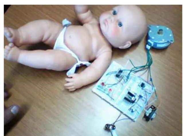
Figure 5: The doll with an artificial “tumor” (a stepper motor, shown near the head of the doll) which is under the control of a PICAXE microcontroller (installed on the proto board).
B. Model II
Here we develop another model to measure the acceleration of the tumor. A rapid change in velocity means the system is either accelerating or decelerating. Since we are dealing with a periodic system, this is a signal that the tumor is about to start its reverse trajectory – time to reduce the motor speed. Hence we focus on measuring the acceleration with the help of the volume of air flowing in. We assume a rectangular lung with varying height (along y axis), as shown in Fig. 2. We also assume that the tumor is on the top and moves up due to the pressure of air flowing in, whereas the “spring” force applied by the lung is forcing it to return to its original position. The system is shown in figure below. The force applied by the air flowing in is given by the product of the pressure and the transverse area of the lung.
In this case, if
L
is the width of the lung along x-axis and c is the depth along z-axis, we can write the volume as:1
dy
dV
dt
Lc
dt
⎛
⎞
=
⎜
⎟
⎝
⎠
(10) All the other variables remain constant. A balance of forces along y-axis yields:y
ma
=
pA ky
−
Where
k
is the spring constant of the lung. We assume that the weight plays no role in this case as the tumor and lung are light-weight spongy objects. Now we have to relate the pressure with the volume of air flowing in. We use, once again, the Bernoulli’s equation and note that the velocity of air flowing in is given by:1 1
1 dV v
A dt =
The velocity on the top of the lung (just below the tumor) can be approximated as zero. Also, the height of the entrance point (labeled 1) can be taken as origin and hence
y
2=
y
. Thus we get2 2
1
1
1
1
1
2
2
dV
p
v
gy
gy
A dt
ρ
ρ
ρ
⎛
⎞
ρ
=
−
=
⎜
⎟
−
⎝
⎠
-20
Figure 6: Typical chest acceleration measurement, in units of (1/100)g (vertical axis), over a period of 55 seconds (horizontal axis).
So finally, the acceleration is related to the change of volume as:
(
)
2
1
1
2
y
A
dV
a
A g
k y
mA
dt
m
ρ
⎛
⎞
ρ
=
⎜
⎟
−
+
⎝
⎠
(12)V. MODELS OF BREATHING
As pointed out earlier, we need a mathematical model of the breathing too. We discuss three simple models.
A. Model I:
The simplest thing to do is to use a cosine form for the rate of change of volume of air, as follows:
cos(
)
L
dV
t
dt
=
α
ω φ
+
(13)
This model obviously is predictive in nature. However, the idea is to keep this behavior a secret for the control electronics and let it follow the tumor using a feedback control loop.
B. Model II:
In this case we assume a constant rate of change which changes its sign with a certain frequency. We can use a simple structure to model this behavior:
cos(
)
cos(
)
L
dV
t
dt
t
ω φ
α
ω φ
+
=
+
(14) C. Model III:Finally we consider a more realistic model based on inhale, exhale, and end of exhale cycle. The end of exhale is faster than sine:
2 2
sin ( ) 0 ( ) 3 / 4
sin ( ) 3 / 4 ( ) 2
L
t
t t
dV
dt t e β t
α
ω φ
ω φ
π
α
ω φ
−π
ω φ
π
⎧ + < + < = ⎨ + < + <
⎩
(15) VI. EXPERIMENTAL SETUP
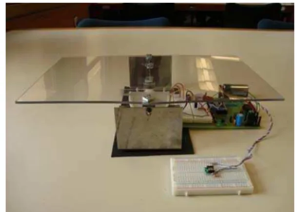
Figure 7: The “tumor” (mounted on a proto board) placed in front of the couch (the plastic sheet assembly).
To test some of the models developed, we have made a prototype system with similar parameters as the models. The lung-tumor system has been made as shown in Fig. 5. We use feedback control [22] shown in Fig. 3 as a block diagram. We use the Parallax Memsic 2125 Dual Axis Accelerometer module [21] to measure the acceleration of the tumor. Its structure is relatively simple. It has a pocket of hot air in the middle and four temperature sensors around it. Depending upon the tilt or acceleration of the accelerometer, the hot gas will collect close to one (or may be two) temperature sensors. The difference in the measurements from the four sensors allows us to measure the acceleration. The PULSIN command used by the Basic Stamp allows us to measure the width of the pulse generated by x or y tilt. This width is proportional to the magnitude of acceleration. Two successive measurements allow us to see if the system is accelerating in one direction or the other. The values of these measurements range between 1875-3125, where a flat accelerometer reads a value of around 2500. This gives a range of ±1250 which has to be handled by the control algorithm. Let
x n
( ) and (
x n
−
1)
be the measurements at timen
and 1
n
−
respectively. We define:( )
( )
(
1)
y n
=
x n
−
x n
−
. Once these measurements have been made, we apply a variant of differential gap control algorithm which can be symbolically written as:IF
( ( )
y n
>
0)
THEN IF
( ( ) 15)
y n
≤
THEN ...ELSE IF
( ( ) 15)
y n
>
AND( ( )
y n
≤
40)
THEN... ELSE IF( ( )
y n
>
40)
THEN...ENDIF
IF
( ( )
y n
≤
0)
THEN IF
( ( )
y n
≥ −
15)
THEN ...ELSE IF ( ( )y n < −15) AND ( ( )y n ≥ −40) THEN... ELSE IF
( ( )
y n
< −
40)
THEN...ENDIF
the interval into further smaller parts and by increasing the data
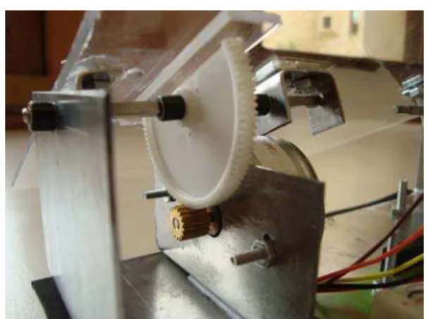
Figure 8: Details of the couch control mechanics. A ‘half gear’ connected to the transparent plastic sheet (on the top) has a lower gear connected to the stepper motor.
collection rate. However for the purpose of this project, a “proof-of-concept” solution was deemed sufficient.
The control system tries to counter the effect of tumor movements simulated in our project using a PICAXE controlled stepper motor with an attached wooden strip [23]. The movements of this strip are “random” in the sense that the corresponding software changes the cycle after every few seconds and this change is not visible to the control circuitry. This system is shown in Fig. 5 with the stepper motor placed outside. The chest of the doll was later cut to make the tumor visible and to make estimates of the quality of the control system.
The measurement of acceleration was a crucial part of this project and we made measurements on various volunteers (both male and female) and a characteristic measurement is shown in Fig. 6. We are currently collecting more data from volunteers over longer periods of time. A detailed Fourier analysis of the frequency spectrum and its significance in real clinical measurements will appear elsewhere [24].
The final completed system is shown in Fig. 7 with all the control electronics placed below the couch. The white proto-board in front of the couch has the accelerometer installed on it and measures the acceleration of the tumor. Fig. 8 shows the details of the mechanical control mechanism with gears
VII. RESULTS AND CONCLUSIONS
A simulation of the mathematical model of the lung-tumor system together with a breathing cycle has been shown to model the behavior of our prototype pretty well. However the movement frequency of the tumor was much higher than the capability of the control circuitry, keeping in view the meager resources available for the project.
We have shown that a real-time tracking of a moving tumor is possible using acceleration sensors placed on the chest. Keeping in view the timidity of the electronics involved, the results are quite promising. Our preliminary results show that a better system, incorporating more degrees of freedom may be developed. The final system will have applications in the
health sector provided we succeed in performing clinical trials.
ACKNOWLEDGMENT
We thank Tec de Monterrey and GIRATE research group for providing the necessary funds to complete this project.
REFERENCES
[1] The American Cancer Society, P.O. Box 22718, Oklahoma City, OK 73123-1718, http://www.cancer.org/
[2] F. V. Fossella, J. B. Jr. Putnam, and R. Komaki (Eds), "Lung Cancer," Springer 2002.
[3] M. Kane, "Biology of Lung Cancer (Lung Biology in Health & Disease)," Informa Healthcare, III edition, 1998.
[4] http://www.medicinenet.com/
[5] J. D. Cox, J. Y. Chang, and R. Komaki, "Image-Guided Radiotherapy of Lung Cancer," Informa Healthcare, 2007.
[6] P. J. Keall, V. R. Kini, S. S. Vedam, and R. Mohan, “Motion adaptive x-ray therapy: A feasibility study,” Phys. Med. Biol. 46, 1–10, 2001. [7] T. Neicu, H. Shirato, Y. Seppenwoolde, and S. B. Jiang, “Moving
aperture radiation therapy SMART: Average tumour trajectory for lung patients,” Phys. Med. Biol. 48, 587–598, 2003.
[8] Y. Suh, S. Dieterich, and P. J. Keall., “Geometric uncertainty of 2D projection imaging in monitoring 3D tumor motion,” Phys Med Biol. 2007 Jun 21; 52(12):3439-54.
[9] E. Weiss, K. Wijesooriya, S. V. Dill, and P. J. Keall, “Tumor and normal tissue motion in the thorax during respiration: Analysis of volumetric and positional variations using 4D CT,” Int J Radiat Oncol Biol Phys. 2007 Jan 1;67(1):296-307.
[10] A. Schweikard, H. Shiomi, and J. Adler, “Respiration tracking in radiosurgery,” Med Phys. 2004 Oct;31(10):2738-41.
[11] A. Schweikard, G. Glosser, M. Bodduluri, M. J. Murphy, and J. R. Adler, “Robotic motion compensation for respiratory movement during radiosurgery,” Comput Aided Surg. 2000;5(4):263-77.
[12] H. Wu, G. C. Sharp, B. Salzberg, D. Kaeli, H. Shirato, and S. B. Jiang, “A finite state model for respiratory motion analysis in image guided radiation therapy,” Phys Med Biol. 2004 Dec 7;49(23):5357-72. [13] D. A. Low, P. J. Parikh, W. Lu, J. F. Dempsey, S. H. Wahab, J. P.
Hubenschmidt, M. M. Nystrom, M. Handoko and J. D. Bradley, “Novel breathing motion model for radiotherapy,” Int J Radiat Oncol Biol Phys. 2005 Nov 1;63(3):921-9
[14] W. D. D’Souza, S. A. Naqvi and C. X. Yu, “Real-time intra-fraction-motion tracking using the treatment couch: a feasibility study,” Phys Med Biol. 2005 Sep 7;50(17):4021-33.
[15] W. D. D’Souza and T. J. McAvoy, “An analysis of the treatment couch and control system dynamics for respiration-induced motion compensation,” Med Phys. 2006 Dec;33(12):4701-9.
[16] K. Sohn, J. E. Holte, J. R. Phillips and W. J. Warwick, “Modeled velocity of airflow in the airways during various respiratory patterns,” Engineering in Medicine and Biology Society, 2004. EMBC 2004. Conference Proceedings. 26th Annual International Conference of the, Volume 2, 2004 Page(s):3925 - 3928 Vol.6
[17] E. R. Weibel, Morphometry of the human lung, Berlin: Springer, 1963. [18] M. N. Ayako, Kokubo, and K. Masaki, “Simulating lung tumor motion for dynamic tumor-tracking irradiation,” Nuclear Science Symposium Conference Record, 2007. NSS '07. IEEE Volume 6, Oct. 26 2007-Nov. 3 2007 Page(s):4549 – 4551
[19] M. Lei, C. Herrmann and K. Schilling, “Modeling and prediction of lung tumor motion for robotic assisted radiotherapy,” Intelligent Robots and Systems, 2007. IROS 2007. IEEE/RSJ International Conference on, Oct. 29 2007-Nov. 2 2007 Page(s):189 – 194. [20] Revolution Education Ltd, Unit 2 Bath Business Park, Foxcote Ave,
Bath, BA2 8SF, UK
[21] Parallax, Inc. 599 Menlo Drive, Rocklin, California 95765, USA. [22] G. F. Franklin, J. D. Powell, and A. Emami-Naeini, Feedback Control
of Dynamic Systems, Prentice-Hall, Upper Saddle River, NJ, 2002. [23] M. A. Yousuf, A. S. Sanders, A. I. S. Ochoa and R. M. F. Somoza,
"Real-time Tumor Tracking – Modeling and Simulating the Process," 7th WSEAS International Conference on Application of Electrical Engineering (AEE’08), Trondheim, Norway, July 2-4, 2008.