for HSRC Beams
ATTAULLAH SHAH*, AND SAEED AHMAD**
RECEIVED ON 26.05.2009 ACCEPTED ON 08.06.2010
ABSTRACT
Experimental research on the shear capacity of HSRC (High Strength Reinforced Concrete) beams is relatively very limited as compared to the NSRC (Normal Strength Reinforced Concrete) beams. Most of the Building Codes determine the shear strength of HSRC with the help of empirical equations based on experimental work of NSRC beams and hence these equations are generally regarded as un-conservative for HSRC beams particularly at low level of longitudinal reinforcement.
In this paper, 42 beams have been tested in two sets, such that in 21 beams no transverse reinforcement has been used, whereas in the remaining 21 beams, minimum transverse reinforcement has been used as per ACI-318 (American Concrete Institute) provisions. Two values of compressive strength 52 and 61 MPa, three values of longitudinal steel ratio and seven values of shear span to depth ratio have been have been used. The beams were tested under concentrated load at the mid span.
The results are compared with the equations proposed by different international building codes like ACI, AASHTO LRFD, EC (Euro Code), Canadian Code and Japanese Code for shear strength of HSRC beams.From comparison, it has been observed that some codes are less conservative for shear design of HSRC beams and further research is required to rationalize these equations.
Key Words: High Strength, Building Codes, Transverse Reinforcement, Shear Span, Beams.
* Project Director, Allama Iqbal Open University, Islamabad.
* * Professor, Department of Civil Engineering, University of Engineering & Technology, Taxila.
1.
INTRODUCTION
The joint committee ASCE-ACI-426 [2] in 1973 and later in 1998 reported the following five mechanisms for the shear in reinforced concrete sections:
(i) Shear in the Un-Cracked Concrete Zone: In cracked concrete member, the un-compression zone offers some resistance to the shear but for slender beams with no axial force, this part is very negligible due to small depth of compression zone.
1.1
Shear Strength of Reinforced Concrete
Beams
T
he research on shear strength of concrete has shown that reinforced concrete beams without transverse reinforcement can resist the shear and flexure by means of beam and arch actions, also sometimes(ii) Residual Tensile Stresses: When concrete is
cracked and loaded in uni-axial tension, it can transmit tensile stresses until crack widths reach 0.06-0.16mm, which adds to the shear capacity of the concrete. When the crack opening is small, the resistance provided by residual tensile stresses is significant. However, in a large member, the contribution of crack tip tensile stresses to shear resistance is less significant due to the large crack widths that occur before failure in such members.
(iii) Interface Shear Transfer: The contribution of interface shear transfer to shear strength is a function of the crack width and aggregate size. Thus, the magnitude decreases as the crack width increases and as the aggregate size decreases. Consequently, this component is also called "aggregate interlock" denoted by Va. However, it is now considered more appropriate to use the terminology "interface shear transfer" or "friction".
(iv) Dowel Action: When a crack forms across longitudinal bars, the dowelling action Vd , of the longitudinal bars provides a resisting shear force, which depends on the amount of concrete cover beneath the longitudinal bars and the degree to which vertical displacements of those bars at the inclined crack are restrained by transverse reinforcement.
Currently, the shear design of the Reinforced Concrete
beams is done with the help of empirical equations proposed by various building codes across the world. These equation have been based on experimental data of
NSRC beams, with compressive cylinder strength of concrete as 40MPa or less. The most commonly used
building codes are discussed as:
1.1.1
ACI Code 318-06
The ACI Building Code 318-06 [3] is no doubt the most widely applied Code for the shear design of concrete. The
nominal shear capacity of reinforced concrete beam Vn, is given as the sum of Concrete contribution Vc, and
contributions of stirrups Vs i.e.
Vn = Vc + Vs
Where Vc is nominal shear strength of concrete, and Vs nominal shear strength of beams due to stirrups.
For beams without shear reinforcement, the shear capacity is given as:
d w b c f d
w b
u M
d u V c
f c
V = ′+
⎥
≤ ′⎦
⎤
⎢
⎣
⎡
3 . 0 7 /
120ρ (1)
The ACI-ASCE Committee 462 has further assumed the
following simplified Equation (1):
(
fc)
bwd cV = 0.167 ' (2)
The shear contribution of transverse steel is given as:
Vs = [Avfyd]/s (3)
Where fc’ is cylinder compressive strength of concrete, ρ
is Longitudinal steel ratio, Vu is Factored shear at the
section, Mu is Factored Moment at the section, bw is
Width of beams web, d is Effective depth of beam, and s is
Spacing of stirrups. FIG. 1. FORCES ACTING IN A BEAM ELEMENT WITHIN THE
1.2.2
Canadian Standards for Design of
Concrete Structures. CSA A-233-94
The General design method of Canadian code has been
based on MCFT (Modified Compression Field Theory)
and applies to concrete up to 81 MPa ( 16000 psi) [4].
According to CSA A- 23.3-94:
300mm d for 06 . 0 if 2 . 0 ≤ ′ ≥ ′ = y f s w b c f v dA w b c f c V 300mm d 06 . 0 if 1 . 0 100 260 ≥ ′ ≥ ′ ≥ ′ + = ⎟ ⎠ ⎞ ⎜ ⎝ ⎛ y f s w b c f v A d w b c f d w b c f d c V (4)
Vs = [AvfyCotθ]/s (5)
Here Av is Areas of the shear steel, fy is Yield stress of
longitudinal steel, and θ is Angle of crack defined under
MCFT.
1.1.3
AASHTO LRFD (Load Reduction
Factor Design) Bridge Design
Specifications-2004 [5]
It is based on MCFT applicable to both non-pre stressed
and pre-stressed concrete and gives:
v d v b c f v d v b fc s
V =0.083β ' ≤0.025 ' (6)
Vs = Avfy dv Cotθ/s (7)
1.1.4
European Code EC2-2003 [6]
For members without shear reinforcement:
(
)
[
]
dw b R
c
V τ κ 1.2+40ρ (8)
τR = 0.0525fc’
Where κ is 1.6-d > 1.0, and ρ is As/bwd < 0.02
For beams with shear reinforcement.
Vs=0.9 ρνfyvbwd (9)
1.1.5
JSCE Code-1986 [7]
According to JSCE (Japanese Japan Society of Civil
Engineers) Code, the shear capacity of linear reinforced
members is given as [6]:
Vcd = βdβpβnfvcdbwd/γb (10)
Where γ is 1.3 for a/d > 2, fvcd is 0.2f’cd1/3 < 0.72, β
d is (1000/
d)1/4 < 1.5, β
p is [0.75 + 1.4 (a/d)], βd is (100ρw) 1/3, and β
n is
[0.75 + 1.4 (a/d)].
For simply supported beams βn=1.
Since we are comparing the test values directly with the
code values therefore γ=1.0, no reduction factor shall be
applied.
Vs = ρufwbwd (11)
A number of researchers have dealt with shear problem of
HSRC beams in different ways and the experimental results
vary from case to case. The results of Cornel University
[8] tests and Perdue University [9] tests have given some
important results for further verification. The findings of
the earlier tests, describing the provisions of ACI Code
for shear strength of HSRC as un-conservative by 10-30%
are a significant outcome. Similarly the later findings at
Perdue University require an increase in the minimum web
reinforcement for compressive strength more than 10,000
psi (70MPa), to avoid brittle failure.
1.3
Evaluation of Shear Design Methods
of Different Building Codes Based on
Test Data Base [10]
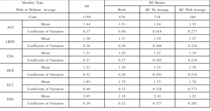
The shear test database of 1359 beams of NSC was studied
by NCHRP (National Cooperative Highway Research
Program), USA which consisted of 878 RC beams and 481 pre-stressed concrete beams. In total of 1359, those
not contain shear reinforcement. The test results Vtest were
compared with the code values Vcode for the six different
codes and the mean and CoV (Coefficient of Variation)
were determined from the Vtest/Vcode values as shown in
Table 1.
The following interesting results were reported in the
study.
CSA and LRFD have given best results particularly for PC beams with shear reinforcement.
ACI provisions are poor predictor of shear for RC and PC
beams with no transverse reinforcement but for beams
with Av, these are reasonably good, hence Av is required
where Vu>ϕVC/2 DIN is very poof predictor followed by
JSCE.
1.3
The Shear Strength of High Strength
Concrete Beams
The research data on the shear strength of high strength
concrete beams is limited particularly for the compressive
strength of 40 MPa and more. Following four challenges
are pointed by Duthinh, et. al. [11] while dealing with the
problem of shear design of high strength concrete.
(i) The current provision and empirical equations
used for the shear design are mostly based on
the research carried with concrete of 40 MPa or
less. Again these equations proposed by
researchers are both complex and difficult to
understand. Hence there is a need to further
simplify these equations for better understanding
and easy application by the designers.
(ii) The minimum shear reinforcement for HSC beams
needs to be rationalized to avoid brittle failure of
the beams and adequate control of the shear
cracks.
(iii) The relatively little role of the aggregate
interlocking in HSC due to stronger matrix, the
shear friction of HSC can be expected 30-35%
less than the NSC.
TABLE 1. COMPARISON OF TEST VALUES AND CODES VALUES BASED ON SHEAR DATA BASE
Member Type
All RC-Beams
With or Without Average Both RC No Average RC With Average
Code 1359 878 718 160
ACI Mean 1.44 1.51 1.54 1.35
Coefficient of Variation 0.37 0.40 0.418 0.277
LRFD Mean 1.38 1.37 1.39 1.27
Coefficient of Variation 0.26 0.26 0.266 0.224
CSA Mean 1.31 1.25 1.27 1.19
Coefficient of Variation 0.27 0.27 0.282 0.218
JSCE Mean 1.51 1.36 1.35 1.38
Coefficient of Variation 0.32 0.28 0.293 0.216
EC2 Mean 1.85 1.75 1.75 1.70
Coefficient of Variation 0.40 0.32 0.328 0.373
DIN Mean 2.05 2.10 2.10 1.25
(iv) The compression capacity of the cracked web is
reduced due transverse section, which is
sometimes referred to as "Softening of concrete",
which depends on the concrete strength.
Duthin, et. al. [11] further highlighted that most of the
current shear design techniques either do not acknowledge
the loss in the aggregate interlock mechanism in high strength concrete or simply do not account for the influence
of adding shear reinforcement to other shear transfer
mechanisms. Johnson, et. al. [10], reported that for a constant low shear reinforcement, the overall reserve shear
strength after diagonal cracking diminishes with increase
in the compressive strength of concrete.
Moinuddin, et. al. [12] applied the concept of FTM (Fracturing Truss Model) rather than MCFT and STM
(Strut and Tie Model), to HSC concrete beams and
compared the test results with the theoretical results. They
observed that the assumption of FTM is more consistent with actual beam failure as compared to MCFT. They also
examined the provisions of ACI-318 and recommended to
include an alternate FTM (Fracturing Truss Model) in the future codes. They also observed that the concretes
having different tensile stresses have significant effect
on the shear capacity of beam, concrete stresses and steel strain. Hence biaxial tests must be conducted rather than
split cylinder test for determining the exact concrete tensile
stresses.
The share of the aggregates interlocking in the overall shear strength of HSRC beams is relatively lesser as
compared to NSRC beams, mainly due the reason that the
strength of concrete matrix in HSC is more than the strength of aggregates. The aggregates thus crush along smooth
plane, thereby reducing the interlocking shear strength of
aggregates [13].
From the above discussions and literature review on the
shear strength of Normal and high strength beams, it has
been deduced that more research is required to understand
the behavior of HSRC beams and provisions of the International building codes.
Cladera, et. al., [13] developed an ANN (Artificial Neural
Network) to predict the shear strength of RC beams, using
a large database of experimental results and made the following important conclusions:
(1) The influence of the amount of web reinforcement
is not linearly proportional to the amount of web
reinforcement. i.e. the shear strength due to increase in shear reinforcement is not increasing
in the same ratio. The effectiveness of stirrups
decreases with their increase.
(2) Due to increase in size at low shear reinforcement, the shear strength has been reduced by 25%
when the size of beam has been increased from
250-750mm.
(3) The influence of compressive strength of concrete also changes with the amount of web
reinforcement.
(4) AASHTO LRFD design equation gives relatively
good results as compared with the ACI-318 and EC-2.
Shehta, et. al. [14] developed theoretical models for the
minimum flexural, shear and torsional for RC beams made
with different compressive strengths of concrete. They reported that due to little test results available, there is
great difference in the minimum values proposed by
different Codes and hence more experimental research has been recommended by them.
Cladera, et. al. [15] worked on the HSRC beams failing in
shear and reported a very brittle failure of the HSRC beams
without shear reinforcement. The failure was observed as
concrete. However, the failure shear strength of beams
was observed to increase with the increase in the compressive strength for such beams. They also proposed
an expression for minimum web reinforcement of HSRC
beams to avoid brittle failure of the beams. They also concluded that the limitation of 2% longitudinal steel for
HSRC beams with web reinforcement is also not justified.
2.
RESEARCH OBJECTIVES AND
SIGNIFICANCE
The objectives of research can be summarized as:
(i) The research is mainly aimed at comparing the provisions of ACI-318, AASHTO-LRFD Code; Canadian Code, European Code and Japanese Code for shear design of HSRC beams with the actually observed experimental values and finally determining their relative degree of safety in the design.
(ii) To study the effect of various parameters like longitudinal steel and shear span to depth ratio on the shear strength of concrete and check how well, these are included in the mentioned codes.
(iii) To compare the relative degree of safety proposed by these codes for HSRC beams with the NSRC beams, based on the observed values.
3.
TESTING DETAILS
To investigate the shear strength of HSRC, 42 beams in two sets of 21 beams each of size 9x12in (23x300cm)
were cast. The values of shear span to effective depth ratios were used as: a/d = 3, 3.5, 4, 4.5, 5, 5.5, 6. For
each value of shear span to effective depth ratio, three
types of longitudinal steel ratios were used (ρ=1, 1.5 and 2%) to study the effect of longitudinal steel ratios.
60 grade steel (140MPa) was used for longitudinal steel.
For Series-I, 21 beams were used without transverse
reinforcement where in Series-II, 21 beams having shear reinforcement with #2 bars of 40 grade ( 276MPa) @ 6 in c/
c ( #6@15cm c/c) were used, .i.e. ρv= 0.17%. The details of beams are shown in Table 2.
The 28 days compressive strength of the concrete mixes was observed as 52 MPa and 61 MPa. The details of mixed
design are given in the Table 3.
4.
RESULTS AND DISCUSSION
4.1
Shear Failure of Beams without Web
Reinforcement
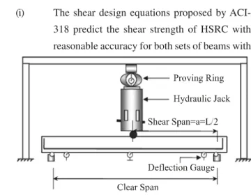
The beams were tested as simply supported beams at the Structural Laboratory of Engineering University
Taxila-Pakistan. Deflection gauges were placed at the mid span
TABLE 2. DETAILS OF MAIN REINFORCEMENT AND TRANSVERSE REINFORCEMENT IN BEAMS
Main Steel Transverse Steel
Bars ρw
Beams Series-I Beams Series-II
(Aw) (%) A
v ρv (%)
2#6 1 0 #2/@6in 0.17
(2#19) (#6@15 cm)
3#6 1.5 0 #3@6in 0.17
(3#19) ( #6@15 cm)
2#7 2 0 #3@6in 0.17
and critical section at d from of the supports as shown in Fig. 2.
When the monotonic load was applied at the centre of
the beams and gradually increased, vertical flexural
cracks appeared in the mid span region. When loads
were increased, inclined cracks also developed in the
region near the supports and their heights were typically
equal to the heights of flexural cracks. With further
increase in the loads, the second branch of the inclined
crack initiates from the tip of the first crack at relatively
flatter angle, which extended towards the point of load
application. The racking of the compression zone, led
to splitting of concrete which ultimately led to the failure
of beams. The failure of HSRC beams without web
reinforcement was observed to be relatively abrupt and
sudden.
4.2
Shear Failure of Beams with Web
Reinforcement
In beams with web reinforcement, the stirrups are brought
into action after the formation of the secondary crack.
With further increase in the width of cracks, the stirrups
also start playing their role. The failure of the beams with
web reinforcement is gradual and less abrupt as compared
to the beams The values of the shear strength of beams
have been shown in Tables 4-5 respectively for both
sets of beams with and without web reinforcement
respectively.
4.3
Comparison of the Provisions of the
Codes for Shear Strength of HSRC
Beams
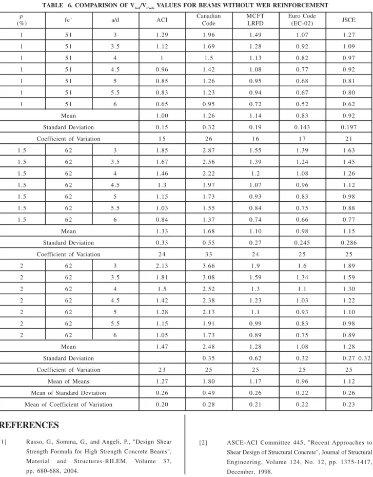
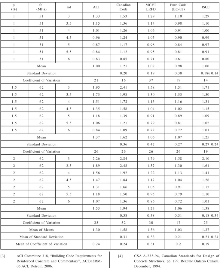
The tests values were compared with the equations
proposed by various building codes for the design of
shear reinforcement of beams both with and without web
reinforcement, shown in Tables 6-7.
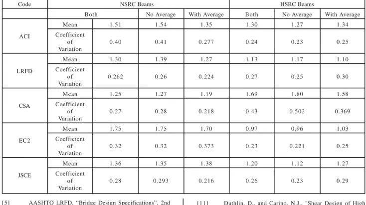
The comparison of the Vtest/Vcode for NSRC beams given in
the shear data base10 are compared with the results
obtained from the testing shown in Table 8.
5.
CONCLUSIONS
From the comparison of specified Code values and actual
test of results of the shear strength of HSRC beams, the
following conclusions can be drawn:
(i) The shear design equations proposed by
ACI-318 predict the shear strength of HSRC with
reasonable accuracy for both sets of beams with
TABLE 3. MIX PROPORTIONING/ DESIGNING OF HIGH STRENGTH CONCRETE
Constituent Mix-I Mix-2
Type- I Cement 628 kg/m3 640 kg/m3
Fine Aggregates 484 kg/m3 960 kg/m3
Coarse Aggregates 1128 kg/m3 1050 kg/m3
HRWR @ by Weight of Cement 10.70 kg/m3 12.58 kg/m3
Water @ 0.25 w/c Ratio 157 kg/m3 160 kg/m3
Average Design Cylinder Compressive Strength ( 28 Days) fc’ 52.0 M Pa 61.0 MPa
and without web reinforcement for longitudinal
steel ratio of 1.5% and more. However for HSRC
beam, the factor of safety has been reduced from
1.51-1.30, thereby recording a reduction of 21% in the shear strength of HSRC beams. However,
the equations are still safe and conservatives for
both types of beams. The equation for the shear
strength of HSRC beams with web reinforcement
is relatively safer.
(ii) The equations of CSA unlike for NSRC,
overestimate the shear strength of HSRC beams,
particularly for beams with no web reinforcement.
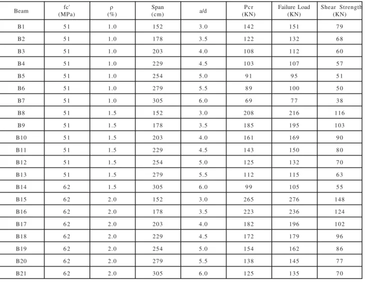
TABLE 4. VALUES OF TOTAL LOADS CORRESPONDING TO SHEAR CRACKS AND SHEAR STRENGTH OF BEAMS WITHOUT STIRRUPS
Beam fc' ρ Span a/d Pcr Failure Load Shear Strength
(MPa) (%) (cm) (KN) (KN) (KN)
B1 5 1 1.0 152 3.0 142 151 7 9
B2 5 1 1.0 178 3.5 122 132 6 8
B3 5 1 1.0 203 4.0 108 112 6 0
B4 5 1 1.0 229 4.5 103 107 5 7
B5 5 1 1.0 254 5.0 9 1 9 5 5 1
B6 5 1 1.0 279 5.5 8 9 100 5 0
B7 5 1 1.0 305 6.0 6 9 7 7 3 8
B8 5 1 1.5 152 3.0 208 216 116
B9 5 1 1.5 178 3.5 185 195 103
B10 5 1 1.5 203 4.0 161 169 9 0
B11 5 1 1.5 229 4.5 143 150 8 0
B12 5 1 1.5 254 5.0 125 132 7 0
B13 5 1 1.5 279 5.5 112 115 6 3
B14 6 2 1.5 305 6.0 9 9 105 5 5
B15 6 2 2.0 152 3.0 265 276 148
B16 6 2 2.0 178 3.5 223 236 124
B17 6 2 2.0 203 4.0 182 196 102
B18 6 2 2.0 229 4.5 172 179 9 6
B19 6 2 2.0 254 5.0 154 162 8 6
B20 6 2 2.0 279 5.5 138 145 7 7
B21 6 2 2.0 305 6.0 125 135 7 0
(iii) The equations of Euro-code EC2 are non
conservative almost for all values of the
longitudinal steel for beams with no web
reinforcement; hence extra care is required in designing the HSRC beams with EC2 building
code.
(iv) The Provisions of LRFD based on MCFT,
appears best predictor of shear strength of
HSRC beams for both types of beams with and
without stirrups. However, simplification is
required for application of the method for shear
(v) The equations proposed by JSCE also predict the shear strength of HSRC beams very reasonably like NSRC beams, though the equations are 16% less conservative for HSRC beams than NSRC beams.
(vi) Based on equations proposed by the five codes, the ratio of Vtest/Vcode for HSRC beams with stirrups is less than the values for the beams without stirrups. Most of the Codes superimpose the individual contribution of concrete and steel to work out the total shear strength of beams with web reinforcement.
However more research is required to prove this basic assumption, as the present results don’t support it.
ACKNOWLEDGEMENTS
The authors are highly grateful to the staff of Structural and Concrete Laboratories, Department of Civil Engineering, University of Engineering & Technology, Taxila, Pakistan, and Higher Education Commission, Pakistan, for their assistance and funding of the work under faculty research project, jointly financed by UET, Taxila, and HEC.
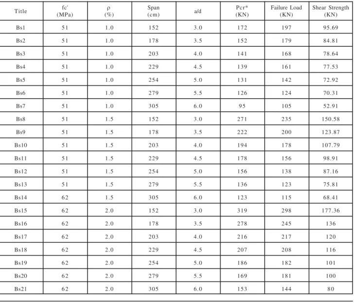
TABLE 5. VALUES OF TOTAL LOADS CORRESPONDING TO SHEAR CRACKS AND SHEAR STRENGTH OF BEAMS WITH STIRRUPS
Title (MPa)fc' (%)ρ Span(cm) a/d (KN)Pcr* Failure Load(KN) Shear Strength(KN)
Bs1 5 1 1.0 152 3.0 172 197 95.69
Bs2 5 1 1.0 178 3.5 152 179 84.81
Bs3 5 1 1.0 203 4.0 141 168 78.64
Bs4 5 1 1.0 229 4.5 139 161 77.53
Bs5 5 1 1.0 254 5.0 131 142 72.92
Bs6 5 1 1.0 279 5.5 126 124 70.31
Bs7 5 1 1.0 305 6.0 9 5 105 52.91
Bs8 5 1 1.5 152 3.0 271 235 150.58
Bs9 5 1 1.5 178 3.5 222 200 123.87
Bs10 5 1 1.5 203 4.0 194 178 107.79
Bs11 5 1 1.5 229 4.5 178 156 98.91
Bs12 5 1 1.5 254 5.0 156 138 87.16
Bs13 5 1 1.5 279 5.5 136 123 75.81
Bs14 6 2 1.5 305 6.0 123 115 68.41
Bs15 6 2 2.0 152 3.0 319 298 177.36
Bs16 6 2 2.0 178 3.5 278 245 136
Bs17 6 2 2.0 203 4.0 216 217 120
Bs18 6 2 2.0 229 4.5 207 208 116
Bs19 6 2 2.0 254 5.0 186 182 101
Bs20 6 2 2.0 279 5.5 169 181 100
REFERENCES
[1] Russo, G., Somma, G., and Angeli, P., "Design Shear
Strength Formula for High Strength Concrete Beams", Material and Structures-RILEM, Volume 37,
pp. 680-688, 2004.
[2] ASCE-ACI Committee 445, "Recent Approaches to
Shear Design of Structural Concrete", Journal of Structural
Engineering, Volume 124, No. 12, pp. 1375-1417,
December, 1998.
TABLE 6. COMPARISON OF Vtest/VCode VALUES FOR BEAMS WITHOUT WEB REINFORCEMENT
ρ
fc’ a/d ACI Canadian MCFT Euro Code JSCE
(%) Code LRFD (EC-02)
1 5 1 3 1.29 1.96 1.49 1.07 1.27
1 5 1 3.5 1.12 1.69 1.28 0.92 1.09
1 5 1 4 1 1.5 1.13 0.82 0.97
1 5 1 4.5 0.96 1.42 1.08 0.77 0.92
1 5 1 5 0.85 1.26 0.95 0.68 0.81
1 5 1 5.5 0.83 1.23 0.94 0.67 0.80
1 5 1 6 0.65 0.95 0.72 0.52 0.62
Mean 1.00 1.26 1.14 0.83 0.92
Standard Deviation 0.15 0.32 0.19 0.143 0.197
Coefficient of Variation 1 5 2 6 1 6 1 7 2 1
1.5 6 2 3 1.85 2.87 1.55 1.39 1.63
1.5 6 2 3.5 1.67 2.56 1.39 1.24 1.45
1.5 6 2 4 1.46 2.22 1.2 1.08 1.26
1.5 6 2 4.5 1.3 1.97 1.07 0.96 1.12
1.5 6 2 5 1.15 1.73 0.93 0.83 0.98
1.5 6 2 5.5 1.03 1.55 0.84 0.75 0.88
1.5 6 2 6 0.84 1.37 0.74 0.66 0.77
Mean 1.33 1.68 1.10 0.98 1.15
Standard Deviation 0.33 0.55 0.27 0.245 0.286
Coefficient of Variation 2 4 3 3 2 4 2 5 2 5
2 6 2 3 2.13 3.66 1.9 1.6 1.89
2 6 2 3.5 1.81 3.08 1.59 1.34 1.59
2 6 2 4 1.5 2.52 1.3 1.1 1.30
2 6 2 4.5 1.42 2.38 1.23 1.03 1.22
2 6 2 5 1.28 2.13 1.1 0.93 1.10
2 6 2 5.5 1.15 1.91 0.99 0.83 0.98
2 6 2 6 1.05 1.73 0.89 0.75 0.89
Mean 1.47 2.48 1.28 1.08 1.28
Standard Deviation 0.35 0.62 0.32 0.27 0.32
Coefficient of Variation 2 3 2 5 2 5 2 5 2 5
Mean of Means 1.27 1.80 1.17 0.96 1.12
Mean of Standard Deviation 0.26 0.49 0.26 0.22 0.26
[3] ACI Committee 318, “Building Code Requirements for Reinforced Concrete and Commentary”, ACI318RM-06,ACI, Detroit, 2006.
[4] CSA A-233-94, Canadian Standards for Design of Concrete Structures, pp. 199, Rexdale Ontario Canada, December, 1994.
TABLE 7. COMPARISON OF VTEST/VCODE VALUES FOR BEAMS WITH WEB REINFORCEMENT
ρ fc’
a/d ACI Canadian MCFT Euro Code JSCE
(%) (MPa) Code LRFD (EC-02)
1 5 1 3 1.33 1.53 1.29 1.10 1.29
1 5 1 3.5 1.15 1.36 1.14 0.98 1.10
1 5 1 4 1.01 1.26 1.06 0.91 1.00
1 5 1 4.5 0.96 1.24 1.05 0.90 0.99
1 5 1 5 0.87 1.17 0.98 0.84 0.97
1 5 1 5.5 0.84 1.12 0.95 0.81 0.91
1 5 1 6 0.63 0.85 0.71 0.61 0.80
Mean 1.00 1.21 1.02 0.98 1.00
Standard Deviation 0.20 0.19 0.38 0.186 0.14
Coefficient of Variation 2 1 1 6 3 7 1 9 1 4
1.5 6 2 3 1.95 2.41 1.58 1.51 1.71
1.5 6 2 3.5 1.73 1.98 1.30 1.33 1.50
1.5 6 2 4 1.51 1.72 1.13 1.16 1.31
1.5 6 2 4.5 1.35 1.58 1.04 1.02 1.15
1.5 6 2 5 1.18 1.39 0.91 0.89 1.09
1.5 6 2 5.5 1.06 1.21 0.79 0.81 1.02
1.5 6 2 6 0.84 1.09 0.72 0.72 1.01
Mean 1.37 1.62 1.06 1.07 1.25
Standard Deviation 0.36 0.42 0.27 0.27 0.24
Coefficient of Variation 2 6 2 6 2 6 2 6 1 9
2 6 2 3 2.26 2.84 1.79 1.58 2.10
2 6 2 3.5 1.89 2.48 1.57 1.30 1.61
2 6 2 4 1.56 1.92 1.22 1.13 1.41
2 6 2 4.5 1.47 1.84 1.17 1.04 1.26
2 6 2 5 1.31 1.66 1.05 0.91 1.15
2 6 2 5.5 1.18 1.50 0.95 0.79 1.10
2 6 2 6 1.07 1.36 0.86 0.72 1.01
Mean 1.53 1.94 1.23 1.06 1.38
Standard Deviation 0.38 0.38 0.31 0.18 0.34
Coefficient of Variation 2 5 3 2 3 0 1 7 2 5
Mean of Means 1.30 1.58 1.36 1.03 1.27
Mean of Standard Deviation 0.31 0.33 0.21 0.21 0.24
TABLE 8. COMPARISON OF THE SHEAR PROVISIONS OF DIFFERENT BUILDING CODES FROM DATA BASE OF NSRC BEAMS WITH THE HSRC BEAMS OF THE CURRENT TEST DATA
Code NSRC Beams HSRC Beams
Both No Average With Average Both No Average With Average
ACI
Mean 1.51 1.54 1.35 1.30 1.27 1.34
Coefficient
o f 0.40 0.41 0.277 0.24 0.23 0.25
Variation
LRFD
Mean 1.30 1.39 1.27 1.13 1.17 1.10
Coefficient
o f 0.262 0.26 0.224 0.27 0.25 0.30
Variation
CSA
Mean 1.25 1.27 1.19 1.69 1.80 1.58
Coefficient
o f 0.27 0.28 0.218 0.43 0.502 0.369
Variation
EC2
Mean 1.75 1.75 1.70 0.97 0.96 1.03
Coefficient
o f 0.32 0.32 0.373 0.23 0.221 0.25
Variation
JSCE
Mean 1.36 1.35 1.38 1.20 1.12 1.27
Coefficient
o f 0.28 0.293 0.216 0.26 0.23 0.29
Variation
[5] AASHTO LRFD, “Bridge Design Specifications”, 2nd Edition, American Association for State Highway and Transportation Officials, Washington, DC, 1998.
[6] Euro Code-2, “Design of Concrete Structures Part-1: General Rules and Rules for Buildings”, Commission of the European Communities, ENV 1992-1-1, pp. 253, December, 1991.
[7] Japan Society of Civil Engineers, “Specification for Design and Construction of Concrete Structures”, Design, JSCE Standard, Part-1, Japan Society of Civil Engineers, Tokyo, 1986.
[8] Collins, M.P., and Mitchell, D., "Shear Design of Pre-Stressed and Non Pre-Pre-Stressed Concrete Beams", Journal of Pre-Stressed Concrete Institute, Volume 25, No. 5, pp. 32-100, 1980.
[9] Bazant, Z.P., and Kim, J.K., "The Size Effect in Shear Failure of Longitudinally Reinforced Beams", ACI Structural Journal, Volume 81, No. 5, pp. 456-468, 1984.
[10] NCHRP (National Cooperative Highway Research Program), Transport Research Board Washington DC-USA, 2005.
[11] Duthlin, D., and Carino, N.J., "Shear Design of High Strength Concrete Beams: A Review of State of the Art", Building and Fire Research Laboratory, NIST MD-USA,
August, 1999.
[12] Mohiuddin, A.K., Edwin, R., and Shah, S., "Shear Design of High Strength Concrete Beams", Structural Journal, ASCE, 2000.
[13] Cladera, A., and Mari, A.R., "Shear Design Procedure for Reinforced Normal and High Strength Concrete Beams Using Artificial Neural Network-Part II Beams with Stirrups", Engineering Structures, Volume 26, pp. 927-936, Elsevier, 2004.
[14] Shehata, I., Shehata, L., and Garcia, S., "Minimum Steel Ratios in Reinforced Concrete Beams Made of Concrete
with Different Strengths-Theoretical Approach", Materials and Structures-RILEM, Volume 36, pp. 3-11, 2003.