Recommendations for verifying lateral stability of
precast beams in transitory phases
Recomendações para veriicação da estabilidade lateral
de vigas pré-moldadas em fases transitórias
a Departamento de Engenharia de Estruturas, Universidade de São Paulo, Escola de Engenharia de São Carlos, São Carlos, SP, Brasil; b Faculdade de Engenharia Civil, Universidade Federal de Uberlândia, Uberlândia, MG, Brasil..
Received: 07 May 2015 • Accepted: 27 Aug 2015 • Available Online: 24 Nov 2015
Abstract
Resumo
This paper presents recommendations for security check of precast beams in transitory phases, compare results of parametric analyzes with national and international code recommendations and confront the formulations used for the calculation of critical load of lateral instability. In transport and lifting phases, precast beams are susceptible to loss lateral stability because the established supports provides little restriction to the element rotate on its principal axis and move laterally. To recommend limits of slenderness, parametric analysis are performed using formulations
based on bifurcacional instability, including eigenvalue problems with the inite element method. The results show that the safety limits for I beams and rectangular beams are diferent. For the analyzed cases and with reference to beam slenderness equation used by ib Model Code [13], the limit determined for rectangular beams would be 85 and for I beams 53, which could be taken as 50, as recommended by the code. Within the analyzed cases of I beams, only the ib Model Code [13] recommendation attend the slenderness limit for transitory phases.
Keywords: lateral instability of beams, precast concrete, lifting, transport, slenderness.
Este artigo objetiva apresentar recomendações para a veriicação da segurança de vigas pré-moldadas em fases transitórias, comparar re-sultados de análises paramétricas com recomendações de normas nacionais e internacionais e confrontar as formulações utilizadas para o cálculo da carga crítica de instabilidade lateral. Nas fases transitórias de transporte e içamento, as vigas pré-moldadas são suscetíveis à perda de estabilidade lateral, porque a vinculação estabelecida oferece pequena restrição ao elemento de girar em torno de seu eixo e deslocar-se lateralmente. Para recomendar limites de esbeltez são realizadas análises paramétricas utilizando formulações baseadas em instabilidade bifur-cacional, incluindo problemas de autovalor com o método dos elementos initos. Os resultados mostram que os limites de segurança para vigas I e retangular são diferentes. Para os casos analisados e tomando como referência a equação de esbeltez de viga utilizada pelo ib Model Code [13], o limite determinado para vigas retangulares seria de 85 e para vigas de seção I seria de 53, o que poderia ser tomado igual a 50, como recomendado pela norma. Dentre os casos analisados de vigas I, somente a recomendação do ib Model Code [13] atende o limite de esbeltez para fases transitórias.
Palavras-chave: instabilidade lateral de vigas, concreto pré-moldado, içamento, transporte, esbeltez.
P. A. KRAHL a
M. C. V. LIMA b
M. K. EL DEBS a
1. Introduction
The increase in concrete strength, improvements in fabrication
process and increase in capacity of transport and lifting
equip-ments enable the production of long slender precast beams. Precast concrete elements are subject to transport and lifting tran -sitory phases. In these situations, the provisory supports do not
restraint the element against twist rotation and lateral delection,
as occurs in permanent phase. In general, transitory situations are considered critical for lateral buckling of precast beams, as pre
-sented by Lima [1] and [2], El Debs [3] and Krahl [4].
Typically, beams have low lateral lexural stifness and when un-dergo rotation about its longitudinal axis part of the self-weight acts laterally. Adding the prestressing efect, the stress state at speciic points of the section (usually the top lange) can overcome the
stress level that causes cracking in concrete.
Thus, it is important check lateral buckling in the design of precast
beams. The veriication can be performed by considering
geomet-ric and material nonlinearities in a complete nonlinear analysis or through safety limits, set by bifurcacional analysis (buckling load). The latter is the base for slenderness limits recommended by codes of concrete structures.
In this context, studies of beam stability which consider support
lexibility are emphasized. According to Trahair [5], exact or
ana-lytical solutions of buckling load cannot be obtained for beams
with lexible supports. Then, it is necessary to utilize numerical methods to obtain approximate solutions as in Lebelle [6], Trahair [5] and Lima [1]. Rayleigh-Ritz method, Galerkin, Runge-Kutta, Finite Diference Method and Finite Element Method are
com-monly used methods that can perform bifurcacional analysis.
Stratford et al. [7] used the inite element method to perform pre-buckling and postpre-buckling analysis to study all beam
load-displace-ment path. Initial geometric imperfections, inclined supports that are not included in bifurcational analysis were considered. Based
on the results, Stratford et al. [7] recommend simpliied formula-tions for calculating critical load. Furthermore, the efect of initial imperfections is considered by Southwell [8] hypothesis.
The current Brazilian codes NBR 9062: 2006 [9] and NBR 6118: 2014 [10] for precast concrete structures and concrete structures do not present recommendations for veriication of lateral stability of beams in transitory phases. Slenderness limits
recommenda-tions of some international codes are presented in Table 1. Cur
-rently, only Eurocode 2 [11] speciies slenderness limit for
transi-tory situation.
As noted, it is necessary to verify beam stability in transitory phas -es to prevent possible damage to the elements which can com
-promise its structural performance. Furthermore, accidents have occurred in these construction phases. Some cases are presented in Krahl [4].
This article provides slenderness limits for precast beams in transi -tory phases. These limits are compared to code recommendations of Table 1. Besides, the results of analytical and numerical models will be compared.
2. Background
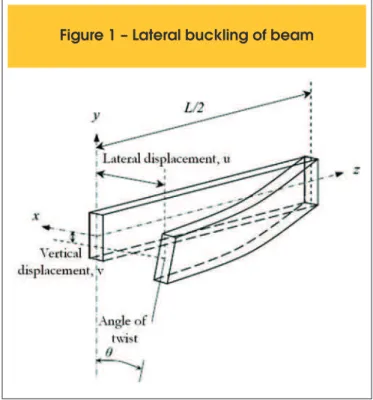
From classical theory of lexural-torsional buckling of beams, such as presented in Timoshenko and Gere [15], it is known that a beam
in bending about its major axis may buckle sideways if its com -pressed region is not laterally restricted. The phenomenon is char -acterized by lateral displacement and twisting rotation, as shown
in Figure 1.
Table 1 – Code recommendations for lateral
stability of concrete beams
Code Slenderness limit
Permanent phase Transitory phase
Eurocode 2 [11] ℓ0f h
1/3 / b f
4/3 < 50
h / bf < 2,5
ℓ0f h1/3 / bf 4/3 < 70
h / bf < 3,5
ABNT NBR 9062 [9]² ℓ0f h / bf
2 < 500
ℓ0f / bf < 50
hm / a > 2
ACI 318-02 [12]¹ ℓ0f / bf < 50
fib Model Code
[13]¹ ℓ0f h1/3 / bf
4/3 < 50
BS:8110-1 [14]¹ ℓ0f h / bf
2 < 250
ℓ0f / bf < 60
ABNT NBR 6118 [10]¹ h / bf < 2,5
ℓ0f / bf < 50
ℓ0f: theoretical span or spacing between lateral restraints;
h: section height;
bf: compressed flange width. For rectangular section change bf for bw;
hm: distance between the center of gravity and the support point;
a: elastic beam lateral displacement, considering the self-weight acting laterally.
Notes¹ do not distinguish between transitory and permanent phases ² As the current version do not contemplate the subject, it is being done reference to previous version.
IBRACON Structures and Materials Journal • 2015 • vol. 8 • nº 6
The nonlinear behavior of beams is inluenced by several factors that can be considered in a simpliied manner in bifurcacional
anal-ysis. They are: type of load, load application point in relation to shear center, support conditions and geometric imperfections. In
transitory phases, the load is the self-weight. Therefore, the irst
and second factors are constant in the problem.
Parametric analyzes will be performed to establish slenderness limits for precast beams. It will be used buckling load solutions
of Lebelle [6], Stratford et al. [7] and eigenvalues using inite
ele-ment method.
The eigenvalue analysis will be performed using free access com
-puter program LTBeam [16]1. The program calculates the lateral
buckling load for beams with several support and load conditions.
The background shall be presented based on Trahair [5].
Lebelle [6] presents buckling load solution for beams with torsion lexible supports. Thus, the beam is partially restricted to rotate by
twisting at the supports. The restriction corresponds to the spring
stifness kθ, equation (1).
(1)
ty crit
crit
k
EI
GI
p
16
3a
l
=
in which,
k: constant which depends on the lange stifness in the case of I section (β coeicient) and of the distance of the support position relative to beam shear center, equation (2);
(2)
d
d
b
0
,
52
0
,
72
47
,
2
1
+
+
2-=
k
where,
β: coeicient that accounts for lateral lange stifness, equation (3);
(3)
2
,
2
l
z
GI
EI
t flanges y
=
b
Iy,langes: weighted average of lange inertias;
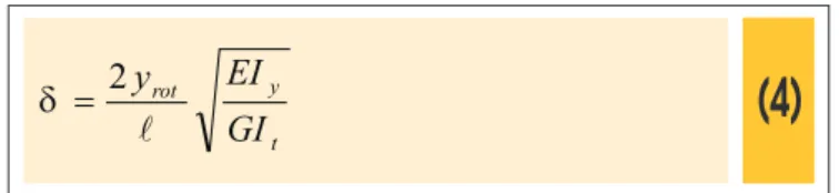
z: distance between lange centroids, z = 0 for rectangular section; δ: coeicient that accounts for support and load positions, equa-tion (4);
(4)
t y rot
GI
EI
y
l
2
=
d
yrot: distance between the loading and support positions;
ℓ: total beam span;
E: concrete modulus of elasticity;
Iy: minor-axis moment of inertia;
G: concrete shear modulus;
It: torsion constant;
αcrit: coeicient which estimates the support deformability efect. Equation (1) can be used for lifting and transportation. The
difer-ences are the distance between the longitudinal axis of rotation position relative to the center of gravity (yrot) and αcrit coeicient particular to each phase.
For lifting, αcrit depends on the attachment point of cables, yrot and lateral lexural and torsional stifness. The constant αcrit can be ob -tained with Table 2. According to Lebelle [6], this variable is related to the function g(α) expressed by Equation (5). Thus, g(α) is cal-culated and αcrit is obtained for a given ratio ϱ=a/ℓ. The overhang
1 [available in https://www.cticm.com/content/ltbeam-version-1011. Accessed on March 28, 2015.]
Table 2 – Values for the coefficient
α
critbased on results of function g(
α
)
g(α) ϱ=a/ℓ
0,5 0,6 0,7 0,8 0,9 1
0,02 2,55 2,4 0,133 0,018 0,0043 0,0014
0,04 10,1 9,23 0,523 0,0716 0,0171 0,0056
0,08 40 31,8 1,95 0,278 0,0672 0,0222
0,16 150,1 83,5 6,28 1 0,253 0,0854
0,32 485,3 148,4 14,8 2,93 0,83 0,297
0,6 1079,5 193,1 23,8 5,76 1,89 0,751
1,2 1833 222,4 31,7 8,9 3,34 1,48
2,5 2396,5 238,4 36,7 11,2 4,57 2,19
5 2678,2 245,9 39,3 12,5 5,29 2,63
10 2817,1 249,7 40,7 13,2 5,68 2,88
20 2885,3 251,6 41,4 13,5 5,89 3,02
40 2919,7 252,5 41,7 13,7 6 3,09
length is a and the total beam span ℓ.
(5)
t y rotGI
EI
y
g
l
4
)
(
a
=
In which yrot is the distance between the loading point and the longi
-tudinal axis of rotation. In transport, αcrit depends on the stifness of the vehicle suspension and the beam torsional stifness. Lebelle [6] presents a function that estimates αcrit and hence the critical load
for a given value kθ, equation (6).
(6)
2 2415800
6617
30
11
1
10395
356
15
8
)
(
2
a
a
a
a
a
q+
-=
=
f
GI
k
tl
For transport, Stratford et al. [7] recommend for buckling load solu-tion the equasolu-tion (7).
(7)
39
,
16
l
t y critGI
EI
p
=
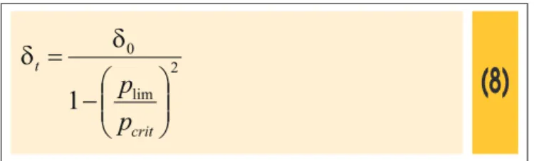
To consider geometric imperfections, Stratford et al. [7] recom-mend to utilize the Southwell [8] hypothesis, equation (8).
(8)
2 lim 01
÷÷
ø
ö
çç
è
æ
-=
crit tp
p
d
d
In which δ0 is the initial lateral displacement. Considering torsional stifness, the relationship between the limit angle θlim and the cor -responding displacement δt, according to Stratford et al. [7], the equation (9) may be adopted.
(9)
rot y t ty
EI
GI
+
=
l
36
,
0
68
,1
limd
q
Thus, with equations (8) and (9) it has three unknowns θlim, δt and
plim. To solution is usually adopted a value for θlim. Whereas the
curves on highways have averaged 8% of superelevation or 4,57 degrees, θlim of 6 degrees or 0,105 rad is conservatively adopted. For two points lifting case by vertical cables, Stratford et al. [7] recommend the equation (10) which estimate the buckling load of
a perfect.
(10)
4 3 2 2 3 42
3
10
12
a
a
a
a
y
EI
p
y rotcrit
-+
-=
l
l
l
l
where,EIy: elastic lateral lexural stifness;
yrot: distance between loading point and the longitudinal axis of ro
-tation;
a
: overhang length; ℓ: total beam span.The Southwell [8] hypothesis is utilized to consider geometric im-perfections, equation (11).
(11)
crit tp
p
a
sen
lim 01
1
-ú
û
ù
ê
ë
é
÷
ø
ö
ç
è
æ
-=
l
p
d
d
In which plim is the limit load that account for initial geometric im -perfection.
Considering the relation between initial lateral displacement δo, i-nal displacement δt and the limit twist rotation θlim, it is known that
a load component plimsenθlim will act laterally (Figure 2) causing the
displacement (δt - δo) expressed by equation (12).
IBRACON Structures and Materials Journal • 2015 • vol. 8 • nº 6
(12)
(
2 2)
5 2y lim sw o
t
δ-
g
384EI
senθ
5
20
4
5
6
δ
÷
ø
ö
ç
è
æ
-=
l
a
l
a
a
l
where,
gsw: self-weight;
θlim: limit twist angle.
Substituting the equation (12) in equation (11), it remains the
un-knowns plim and θlim in the resulted expression. To obtain plim is uti
-lized the recommendation by Mast [17] to limit twist angle. Mast [17] performed experiments with a real scale beam PCI BT-72 and stablished a limit angle of 23 degrees for lifting.
The computational program LTBeam [16] is utilized in parametric
analysis. The buckling load is obtained by calculating the smaller
eigenvalue for a beam discretized in 100 inite elements. Trahair [5] presents a procedure to implement the eigen-problem with inite element method (FEM).
To obtain the eigenvalues λcr and eigenvectors {δ} using FEM is necessary to obtain irst the stability matrix [G] for each el-ement, besides the stifness matrix [K]. The stability matrix is
obtained from energy portion correspondent to the work varia
-tion of external loads. The eigen-problem can be represented by equation (13).
(13)
([K] –
l
cr[G]){
d
} = 0
The load path of the model is set on stability matrix [G]. To solve equation (13) the matrix [G] must be inverted by utilizing a nu-merical method to obtain λcr. Other possibility is invert the stif-ness matrix and get 1/λcr. To obtain critical values just multiply λcr
by the load path adopted.
The program enables to insert discrete lexible supports. Springs
can be insert to partially restraint lateral displacement, rotation by
lateral lexure, twist rotation and warping. For transitory phases, the torsional stifness of the supports is the major parameter.
3. Results and discussion
The results of parametric analysis are presented for beams in transitory phases by utilizing the formulation of bifurcational anal
-ysis. The study of rectangular and I-section beams are performed
separately. The smaller slenderness ratio obtained from buckling analysis will be adopted as safety limit.
The graphs present results of lifting phase along with transport
phase. Geometric relations to obtain slenderness ratios were de-termined in accordance with Eurocode 2 [11]. The code limits for transitory phases are expressed in equation (14).
(14)
3,5
b
h
f£
and
7
0
b
h
4/3 f 1/3 0f£
l
To obtain slenderness limits the safety criterion pcrit / pp > 4 is
considered which is adopted due to the diiculty in predicting how the transitory phases will be performed. Krahl [4] presented a smaller limit by utilizing the formulation of Mast [17]. However,
the oldest value will be utilized to obtain slenderness limits. Increase in compressive strength of concrete has a positive ef -fect on lateral buckling of precast beams. Thus, in a conserva
-tive way it is considered a compressive strength of 30MPa in all analysis which is slightly smaller than the strength required for
permanent phase.
Geometric imperfections and deviations in positioning the beam supports as lifting cables or truck suspension system can signii-cantly reduce the safety against buckling. The inluence of these factors is evaluated in Krahl [4].
The slenderness ratios presented in equation (14) are not
afect-ed by geometric imperfection variation and concrete modulus of elasticity as well. To consider them is necessary an expression
that utilize buckling load. However, the codes of concrete struc-tures recommend limits as equation (14). Thus, in a
conserva-tive way, the geometric slenderness limits are obtained for the
imperfection recommended by Eurocode 2 [11] that is ℓ/300 as
initial lateral displacement. In all analysis an overhang of 2,5m is considered.
Some of the formulations enable the use of lexible supports. Ac-cording to Mast [17], it is recommended as torsion spring stif-ness for beam in transport a value between 360 to 680kN.m/rad per dual-tire axel. In this article, it is adopted four dual-tire axel plus one simple-tire axel for the tractor resulting in 1530 kN.m/rad (360 kN.m/rad per dual-tire). The same is adopted for the trailer.
The considered torsion spring for lifting is 1200 kN.m/rad.
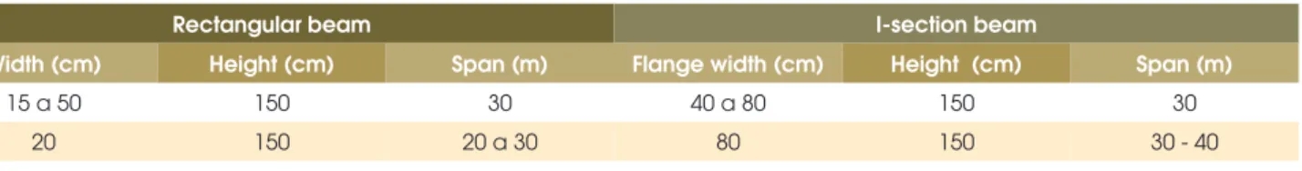
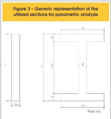
Table 3 shows the geometric relations utilized in parametric analysis. The flange and web thickness of I-section beams are fixed in 15 cm. Figure 3 shows the generic representation of
the section.
3.1 Width variation of rectangular beam
Table 4 presents the buckling load results for rectangular beam
Table 3 – Geometric properties of analyzed precast elements
Rectangular beam I-section beam
Width (cm) Height (cm) Span (m) Flange width (cm) Height (cm) Span (m)
15 a 50 150 30 40 a 80 150 30
with widths of 15, 20, 30, 40 e 50 cm. The section height is 150 cm and beam span 30 m, with ℓ / h = 20.
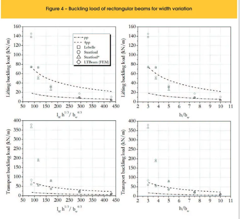
In Figure 4, the dash-dotted line represents the self-weight and the
dashed line represents four times this value. The latter being the safety criterion. The graphs for transport and lifting are presented
separately in Figure 4 in which the buckling load is related to geo-metric slenderness from equation (14).
According to Figure 4, as the beam width increase the buckling
load increase, tending to exceed the safety limit. In lifting phase
with slenderness ℓ0f h
1/3 / b
w
4/3 ≤ 85 and h / b
w≤ 3 the safety is veriied. The irst limit is bigger than Eurocode 2 [11] and ib Model Code [13] recommendations. The second is smaller than Eurocode 2 [11] limit, so the code limit is unsafe.
To ℓ0f h / bw
2 slenderness, it is obtained the limit of 180 that cor -responds to a safe buckling load that is smaller than BS:8110-1 [14] and ABNT NBR 9062:2006 [9] recommendations, as shown in
Table 1. Thus, the Britain and Brazilian codes recommend unsafe limits for rectangular beams in transitory phases.
The slenderness ℓ0f / bw results 60 which coincides with the BS:8110-1 [BS:8110-14] recommendation. ACI 3BS:8110-18-02 [BS:8110-12] and ABNT NBR9062:2006 [9] recommendations are conservative therefore safe.
In transport, the formulation of Lebelle [6] does not achieve the determined limit in lifting, as shown in Figure 4. However, the other
formulations checked the safety in transport for the same limit in lifting.
In the graphs of Figure 4, it is veriied that the formulation of Strat-ford et al. [7] tends to present high buckling load as the
slender-ness is decreased. In the lifting case, this formulation presents high sensibility to geometric imperfections, wherein for slenderness
ℓ0f h
1/3 / b
w
4/3 = 86,53 the reduction in buckling load is 48%.
In lifting, the formulation of Stratford et al. [7] that considers
geo-metric imperfections had results that agree with those obtained by
inite element method (LTBeam). For the smaller slenderness con-sidered the diference is 1,12% and 6,75% in the irst two cases. However, as the slenderness ratio increases the diference is in-creased to 64%.
In the case of transport phase, the formulation of Lebelle [6] had
results that agree with those obtained by the computational pro
-gram LTBeam [16] for high slenderness, but as the slenderness decreases the diference increases. For the range of slenderness ratio studied the extreme diferences are 7,7% and 28,4%. For lift-ing, the formulation of Lebelle [6] presents large variation in
buck-ling load as the slenderness decreases.
3.2 Span variation of rectangular beam
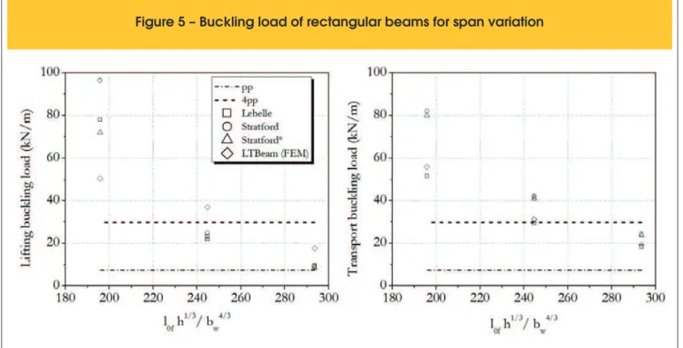
For evaluating the inluence of span variation in buckling load the present spans are adopted 20, 25 and 30 m. Table 5 and Figure
5 present the results. The rectangular section is 20 cm wide and 150 cm high, thus the relation h / bw has a constant value of 7,5.
According to the limit obtained in item 3.1, this value do not verify
the safety limit h / bw≤ 3. The ℓ / h relations are 13, 17 and 20.
According to Figure 5, in the case of beams with slenderness ℓ0f h
1/3 / b
w
4/3 ≤ 200 all formulations present buckling load results
that verify the safety for lifting and transport. In this point, it is clear the limitation of the geometric slenderness limits recom -mended by codes.
On the recommendation of item 3.1 (ℓ0f h
1/3 / b
w
4/3 ≤ 85 e h / b
w≤ 3),
Figure 3 – Generic representation of the
utilized sections for parametric analysis
Table 4 – Buckling load of rectangular beams for width variation
h / bw ℓ0f h1/3 / b w
4/3
Buckling load (kN/m)
Lebelle Stratford et al. Stratford et al.¹ LTBeam
I² T I T I T I T
10,00 430,89 4,07 10,62 3,82 10,24 3,73 9,87 10,45 11,51
7,50 293,62 9,55 18,43 9,14 24,28 8,61 23,40 17,61 19,64
5,00 171,00 31,5 35,37 31,13 81,96 25,78 79,00 34,14 38,38
3,75 116,52 72,75 53,63 74,13 194,30 49,70 187,20 53,32 60,09
3,00 86,53 138,30 60,48 145,17 379,45 74,06 365,63 74,9 84,50
769
IBRACON Structures and Materials Journal • 2015 • vol. 8 • nº 6
Figure 4 – Buckling load of rectangular beams for width variation
Table 5 – Buckling load of rectangular beams for span variation
Vão (m) ℓ0f h1/3 / b w
4/3
Buckling load (kN/m)
Lebelle Stratford et al. Stratford et al.¹ LTBeam
I² T I T I T I T
20 293,62 9,55 18,43 9,14 24,28 8,61 23,79 17,61 19,34
25 244,68 23,20 29,49 24,83 41,96 22,03 41,03 37,00 31,20
30 195,74 77,80 51,50 96,30 81,96 71,94 79,93 50,40 55,78
the beam with relation h / bw= 7,5 and span of 20 m do not verify
safety against buckling ℓ0f h1/3 / bw4/3 = 293,62. However, the result
obtained in this item shows that the criterion pcrit / pp > 4 is veriied,
as presented in Figure 5.
For lifting, the formulations of Lebelle [6] and Stratford et al. [7] present closed results with the biggest diference of 7,5%. Com-paring the results of the formulation of Stratford et al. [7] with those of the program LTBeam [16], the biggest diference is 51,1%. In transport, this occurs for the results of Lebelle [6] and LTBeam [16], with the maximum diference of 7,7% and minimum of 4,7%. The formulation of Stratford et al. [7] shows small sensibility to geo-metric imperfections in transport, because the biggest diference
between buckling loads considering and not geometric imperfec -tion is 2,5%.
In Table 6, the results of this item are compared to those of item
3.1. For this item the beam with 20 m span is considered. From
this comparison, it can be recommended the slenderness ratio ob
-tained in item 3.1. The slenderness ℓ0f h / bw
2 limit obtained for beams with rectan
-gular sections is 180 whereas in ABNT NBR 9062:2006 [9] is 500,
thus the code recommendation is unsafe.
To exemplify the obtained limit, consider for example a beam 40
cm wide, 150 cm high and a span of 20 m. Its slenderness is
ℓ0f h
1/3 / b
w
4/3 = 7,7 . The ib Model Code [13] recommends a value of
50 as slenderness limit, thus the beam in question do not verify this criterion. However, this precast element veriies the safety criterion obtained in the item 3.1 which is 85. It should be pointed out that
the limits obtained in this article are based on the safety criterion pcrit / pp > 4.
3.3 Flange width variation of I-section beam
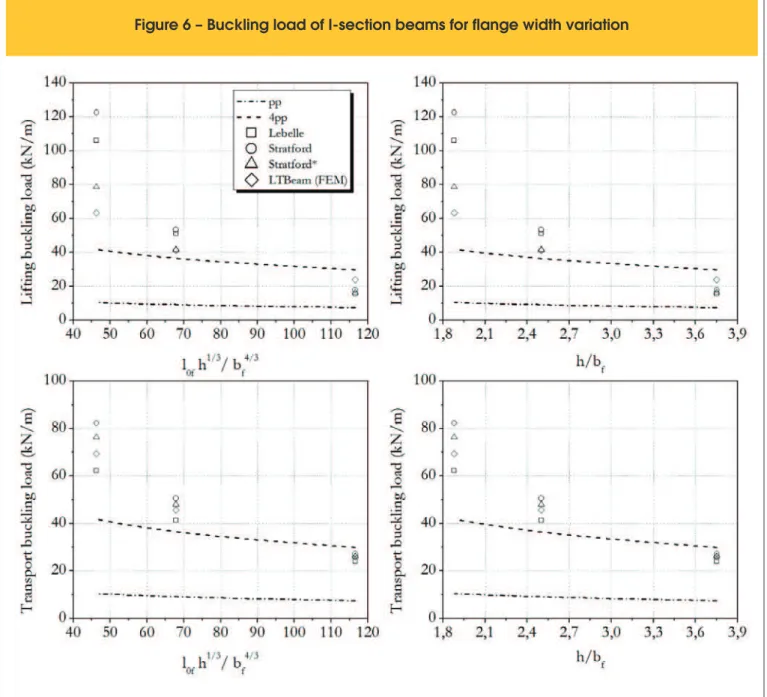
Table 7 and Figure 6 present the buckling load results for simultane-ous variation of top and bottom langes width of I-section beam in transitory phases. The admitted widths are 40, 60 and 80 cm and the height, thickness of web and langes and the beam span are ixed in 150 cm, 15 cm and 30 m, respectively, with the relation ℓ/ h= 20 .
According to Figure 6, the results show that for slenderness ratios ℓ0f h1/3 / bf4/3 ≤ 70 and h / bf
≤ 2,5 all formulation present buckling
loads that verify the safety criterion for transport and lifting. Com
-parison with codes will be done in item 3.4.
The formulation of Stratford et al. [7] presents similar behavior as de-scribed in item 3.1. In lifting, the author’s formulation agree well with the results of LTBeam [16], being the maximum diference of 31,5%. In transport, the results of the formulation of Lebelle [6] are similar to those of LTBeam [16], being the maximum diference of 10,1%.
3.4 Span variation of I-section beam
The importance of span variation in the stability of I-section beams is veriied in this item. Table 8 and Figure 7 present the results.
Figure 5 – Buckling load of rectangular beams for span variation
Table 6 – Comparison of slenderness limit
results for rectangular beams
Slenderness ratio Item 3.1 Item 3.2
ℓ0f h1/3 / bw
4/3 85 195
ℓ0f h / bw
2 180 750
ℓ0f / bw 60 100
IBRACON Structures and Materials Journal • 2015 • vol. 8 • nº 6
Table 7 – Buckling load of I-section beams for flange width variation
h / bf ℓ0f h1/3 / b f
4/3
Buckling load (kN/m)
Lebelle Stratford et al. Stratford et al.¹ LTBeam
I² T I T I T I T
3,75 116,52 15,56 23,97 17,89 27,18 16,3 26,25 23,80 25,96
2,50 67,86 51,2 41,4 53,3 50,61 41,5 48,04 41,24 45,65
1,88 46,24 105,97 62,29 122,5 82,19 78,6 76,4 63,24 69,29
Notes ¹ Formulation which considers geometric imperfection ² The letters I and T represent lifting and transport, respectively.
Table 8 – Buckling load of I-section beam for span variation
Vão (m) ℓ0f h1/3 / b f
4/3
Buckling load (kN/m)
Lebelle Stratford et al. Stratford et al.¹ LTBeam
I² T I T I T I T
30 46,24 105,97 62,3 121,84 82,2 78,14 76,36 63,24 69,29
35 53,95 45,40 42,10 55,40 51,75 42,20 48,25 42,25 46,12
40 61,66 23,73 29,86 28,93 34,67 24,27 32,4 29,7 32,31
Notes ¹ Formulation which considers geometric imperfection ² The letters I and T represent lifting and transport, respectively.
The admitted spans are 30, 35 and 40 m, being the relation ℓ / h
of 20, 23 and 26, respectively. The lange width, lange and web thickness and section height are ixed in 80 cm, 15 cm e 150 cm,
respectively. Thus, the relation h/ bf is constant with value of 1,88.
In Figure 7, safety is checked for slenderness of ℓ0f h1/3 / bf4/3 ≤ 53 in lifting and transport. This result is close to
the limit recommended by ib Model Code [13]. The slenderness h/ bf ≤ 1,8 can only be recommended if simultaneously verify the slenderness ℓ0f h
1/3 / b
f
4/3 .
Imposing these safe limits, some cases of beams that verify stabil
-ity in transitory phases by buckling load shall not be accepted. For example, the beam with slenderness ℓ0f h
1/3 / b
f
4/3 = 67,8 presented
in item 3.3 which veriies the criterion pcrit / pp > 4.
The results patterns are equal to those presented in the preced-ing items. In liftpreced-ing, the formulation of Stratford et al. [7] presented results whose maximum diference is 18,3% to formulation of LT-Beam [16]. In transport, the maximum diference between the for-mulations of Lebelle [6] and LTBeam [16] is 7,6%.
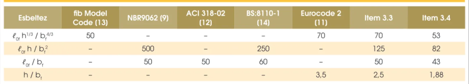
In Table 9, the slenderness limits obtained in item 3.3 and item 3.4
are compared with code recommendations.
In accordance with Table 9, the only code that presents safe
slen-derness limit, when compared with the results obtained, is the ib
Model Code [13]. Therefore, for I-section beams the recommended limits are those obtained in item 3.4. The slenderness ℓ0f h1/3 / bf4/3
can be assumed as the value of ib Model Code [13].
As did in item 3.2 for exempliication, it is considered now an I-section beam with lange widths, web and lange thickness, height
and span of 50 cm, 15 cm, 150 cm and 20 m, respectively. Its
slenderness is ℓ0f h
1/3 / b
f
4/3 = 57,7 . This slenderness does not
verify the veriication of ib Model Code [13] nor the limit obtained
in this article.
4. Conclusions
Based on results of parametric analysis, it can be concluded:
773
IBRACON Structures and Materials Journal • 2015 • vol. 8 • nº 6
formulation of Stratford et al. [7] presented results that agree
with those obtained by the computational program LTBeam
[16] which was taken as reference. For the slenderness range considered for rectangular and I-section beams, the minimum diference between buckling load curves was 1,1% and maxi-mum 64%.
b) The buckling load results for transport from formulation of Leb
-elle [6] have approached the results of LTBeam [16]. Between the considered slenderness for rectangular and I-section beams, the minimum diference obtained in the buckling load curves was 4,7% and maximum of 28,4%.
c) The slenderness limit determined for rectangular beams is
diferent from the limit encountered for I-section beams. It is
important to note that none code does this distinction. There -by, the rectangular beams usually result excessively robust, wherein the buckling load calculation shows that the elements could be more slender.
d) Taking ib Model Code [13] as reference, the limit of the
slen-derness ℓ0f h1/3 / bf4/3 for rectangular beams would be 85, for the
analyzed cases.
e) For I-section beams, the limit determined for ℓ0f h
1/3 / b
f
4/3 is 53
that could be taken equal 50, as recommended by ib Model Code [13].
f) In the studied cases for I-section beams, only the
recommen-dation of ib Model Code [13] meets the slenderness limits for the analyzed cases.
Note the conclusions were obtained for a study that involved the following situations: fck of 30 MPa, geometric imperfection of ℓ/300 (when considered), overhangs of 2,5 m, vertical lifting cables, safe -ty criterion pcrit / pp > 4. The torsional spring stifness adopted in
lifting is 1200 kN.m/rad and transport 1530 kN.m/rad.
The geometric relations utilized were presented in Table 3. Re-membering that the lange and web thickness are ixed in 15 cm. When the code recommendations are not met, it can be appealed
to a more rigorous analysis, for example, buckling load calculation.
This type of analysis considers the efect of geometric
nonlineari-ties that is characteristic in slender beams. The safety is then veri
-ied by comparing the buckling load to the beam self-weight. The relation between the two quantities must meet always to a safety criterion, usually it is adopted a value of 4.
5. Acknowledgments
The authors would like to thank to the Department of Structural En-gineering of University of São Paulo and to the Brazilian research funding agency CAPES for the master’s degree scholarship.
6. References
[1] LIMA, M. C. V. Instabilidade lateral das vigas pré-moldadas em serviço e durante a fase transitória, São Carlos, 1995, Dissertação (Mestrado), Escola de Engenharia de São Car-los – USP, 146p.
[2] LIMA, M. C. V. Contribuição ao estudo da instabilidade lat-eral de vigas pré-moldadas, São Carlos, 2002, Tese (Douto-rado), Escola de Engenharia de São Carlos – USP, 179 p. [3] EL DEBS, M. K. Concreto pré-moldado: fundamentos e
apli-cações. São Carlos, EESC-USP - Projeto Reenge, 2000. [4] KRAHL, P. A. Instabilidade lateral de vigas pré-moldadas em
situações transitórias, São Carlos, 2014, Dissertação (Mes-trado), Escola de Engenharia de São Carlos - USP, 209 p. [5] TRAHAIR, N. S. Flexural-Torsional Buckling of Structures.
London: E. & F. N. Spon, 1993, 360 p.
[6] LEBELLE, P. Stabilité élastique des poutres en béton pré-contraint a l’égard de déversement latéral. Ann. Batiment et des Travaux Publics, v. 141, p. 780–830, 1959.
[7] STRATFORD, T. J.; BURGOYNE, C. J.; TAYLOR, H. P. J. Stability design of long precast concrete beams. Proceed-ings of the Institution of Civil Engineers – Structures and Bridges, v.134, p.159-168, 1999.
[8] SOUTHWELL, R. V. On the analysis of experimental
obser-vations in problems of elastic stability. Proceedings of the
Royal Society, v. 135, p. 601–616, 1932.
[9] ASSOCIAÇÃO BRASILEIRA DE NORMAS TÉCNICAS. Projeto e execução de estruturas de concreto pré-moldado. - NBR 9062, Rio de Janeiro, 2001.
[10] ASSOCIAÇÃO BRASILEIRA DE NORMAS TÉCNICAS. Projeto de estruturas de concreto - Procedimento. NBR 6118, Rio de Janeiro, 2014.
[11] EUROPEAN COMMITTEE OF STANDARDIZATION. De-sign of Concrete Structures - Part 1-1: General rules and rules for buildings. - EUROCODE 2, Brussels, 2004. [12] ACI COMMITTEE 318, “Building Code Requirements for
Structural Concrete (ACI 318-02) and Commentary (318R-02),” American Concrete Institute, Farmington Hills, Mich., 2002, 443 pp.
[13] FÉDÉRATION INTERNATIONALE DU BÉTON, ib Model Code 2010 - inal draft, Vol. 2, Bulletin 66, Lausanne,
Swit-zerland, 2012.
[14] BRITISH STANDARDS INSTITUTION, BS 8110. Code of practice for structural use of concrete. London; 1997. [15] TIMOSHENKO, S.; GERE, J. Theory of Elastic Stability.
Mc-Graw Hill, New York, 1988, 541p.
Table 9 – Comparison of slenderness limit results for I-section beams
Esbeltez fib Model
Code [13] NBR9062 [9]
ACI 318-02 [12]
BS:8110-1 [14]
Eurocode 2
[11] Item 3.3 Item 3.4
ℓ0f h 1/3 / b
f
4/3 50 – – – 70 70 53
ℓ0f h / bf
2 – 500 – 250 – 125 82
ℓ0f / bf – 50 50 60 – 50 43
[16] LTBeam 1.0.10 [Computer software]. Saint-Aubin, France, Centre Technique Industriel Construction Metallique (CTICM).