Daniel Amariei, Ion Vela, Cornel Mituleţu, Marius Tufoi
Contributions to Design of Actuators functioning
with Nitinol Active Springs
The paper presents the research results achieved in order to perform a comparison regarding the influence of natural and forced cooling proc-ess applied to the Nitinol active springs inside a linear motion actuator. SMAs offer attractive potentials such as reversible strains of several percent, generation of high recovery stresses and high power / weight ratios. The actuator behavior was simulated first with SolidWorks and experimentally tested for results validation.
Keywords: actuators, Nitinol, springs, simulation, stroke
1. Introduction
In the recent past period a lot of effort has been performed to the design, the construction and the control of the new types of actuators, especially the ones driven by shape memory alloys (SMA), owed to the large range of application which involves them (robotic devices, automotive safety devices, vibration redemp-tion, sensing devices etc.). Basically, SMAs are functional materials being able to convert their shape to a pre-programmed structure. Their importance is high-lighted more for their performance as an action than for what represents as com-position. SMAs one way memory effects suppose modifying the initial geometrical shape, the recover of that original induced shape being possible after exceeding a certain temperature point.
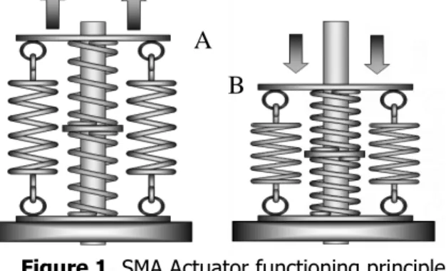
The paper presents the influence to stroke and velocity of an actuator includ-ing two tension sprinclud-ings workinclud-ing in parallel and two compression sprinclud-ings workinclud-ing in series (Figure 1), which occurs in the case of natural and forced cooling method.
ANALELE UNIVERSITĂŢII
“EFTIMIE MURGU” REŞIŢA
2. The Actuator.
The working principle of the actuator is based on the antagonistic way in which the compression and tension springs works, each of them serving to de-formed the others, producing in this way the continuous linear movement per-formed by the actuator. The working principle is presented in Figure 1.
Thus, the first phase consist of heating up the compression springs to the ac-tivation temperature bring them to the initially induced shape, putting the actua-tor’s support disc in the A position, generating in the meantime the deformation force for the tension springs, which are stretched from their initial shape with around 30% of their initial length.
In the same manner, the second phase deals with heat up this time the ten-sion sprigs to the activation temperature bring them to the initially induced shape, which causes the stroke of the support disk from A to B position, pressing in the same time the compression springs with around 30% of their normal lenght, and bringing the entire system the first phase described in the paragraph above.
Figure 1. SMA Actuator functioning principle
The working principle was tested at the beginning through a simulation per-formed using the SolidWorks software.
In order to perform the simulation, preceding the entire assembly building were designed geometrically each part of the proposed actuator version and were established positions and interdependencies between them.
Motion Study analysis revealed the fact that the maximal actuator stroke is 35 mm, as presented in Figure 2. The actuator simulation’s defining characteristics were considered to be as starting time 0 sec and duration of 10 sec. The option for analysis steps was considered to be Automatic Increment, allowing the actuator to perform large displacements and having large deformations. Was included also the thermal effect, including thermal loadings, the temperature for 0 deformation be-ing considered 22° C.
The analysis type was FFEPlus, this method being preferred in the case of non linear analysis because it supposes an iterative solving procedure, assuming an
approximately solution for solving the algebraic equations. Afterwards the errors are quantified followed by successive reiterations until the total error amount is enclosed inside the admitted and set-up interval, the association option for incom-patibility being thus more precise.
Figure 2. Actuator’s stroke simulation with SolidWorks software
0 1 2 3 4 5 6 7 8 9 10 0 0 ,4 0 ,8 1 ,2 1 ,6 2 2 ,4 2 ,8 3 ,2 3 ,6 4 4 ,4 4 ,8 5 ,2 5 ,6 6 6 ,4 6 ,8 7 ,2 7 ,6 8 8 ,4 8 ,8 9 ,2 9
,6 10
Time [s] S tr o k e [ m m ]
Natural Cooling Forced Cooling
0 1 2 3 4 5 6 0 0 ,4 0 ,8 1 ,2 1 ,6 2 2 ,4 2 ,8 3 ,2 3 ,6 4 4 ,4 4 ,8 5 ,2 5 ,6 6 6 ,4 6 ,8 7 ,2 7 ,6 8 8 ,4 8 ,8 9 ,2 9
,6 10
Timp [s] V e lo c it y [ m m /s ]
Natural Cooling Forced Cooling
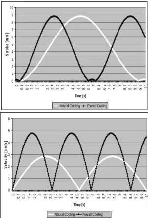
Figure 3. Simulation results of stroke and velocity evolution
As control technique the option was Forced Solving, the iteration technique being considered the Newton-Rapson one, this being successive identification method of the best approximation in regard to solutions or 0 real values of the considered function. For integration was chosen to solve the differential equations the Newmark method, respectively for numerical evaluation of the dynamic re-sponses of structures and solids during the FEM dynamic analysis.
Figure 3 presents the driving element’s characteristic point for both situations considered, respectively natural and forced cooling method of the SMA spring.
Stroke value decrease drastically from 9,65 seconds when the elements are naturally cooled to 5,68 seconds when air flow is blown. In case of velocity, the natural cooling situation presents a maximum value of 2,87 mm/sec, a complete cycle (back and forth) duration being 5,73 seconds. Contrary to natural cooling method, the complete cycle duration becomes 2,82 seconds for the forced cooling procedure, the maxim velocity reaching 4,96 mm/sec.
Simulation was repeated after a model recheck and set-up analysis in order to simplify the model. Simulation duration was approximately the same, the results having approximately the same values too, which provide the conclusion that the model is conclusively.
The research continued after simulation with the obtained results experimen-tal validation.
In order to perform experimental tests, was build-up the actuator showed in Figure 4, consisting of two tension springs made of 0,750m wire, with 6 mm coil diameter and two compression springs made of 0,950 mm wire and 8 mm coil di-ameter.
Figure 4. Actuator based on four Nitinol springs (2 tension and 2 compression)
Each actuator’s tension spring is capable to lift a 450 grams weight, allowing a linear extension up to 85 mm. The 2 Amps activation current heats it up to 500 - 550C when the shape memory effect appears and brings the tension spring to the initially induced length of 17 mm.
On the other hand, the compression springs minimal length, meaning the spring is maximally compressed, is 17,4 mm. The activation current of 3 Amps produces the shape memory effect at 550 - 650C, capable to develop a force of
Figure 5. Elastic piping system attached for forced cooling
In order to purge an air flow on the springs needed for the forced cooling sit-uation, an elastic piping system was attached to the actuator, offering the oppor-tunity to cool down sequentially the sprigs pairs (Figure 5).
0 1 2 3 4 5 6 7 8 9 10
0,0 0,5 1,01,5 2,02,5 3,0 3,54,0 4,55,05,56,06,57,0 7,58,0 8,59,0 9,510,0
Time [s]
S
tr
o
k
e
[
m
m
]
Simulation Experimental
0 1 2 3 4 5 6 7 8 9 10
0,0 0,5 1,0 1,5 2,0 2,53,0 3,5 4,04,5 5,0 5,5 6,0 6,5 7,0 7,5 8,0 8,59,0 9,510,0
Time [s]
S
tr
o
k
e
[
m
m
]
Simulation Experimental
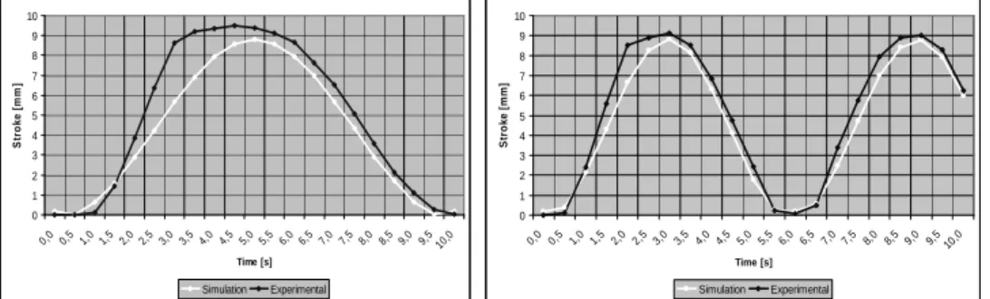
Figure 6. Experimental and simulation results stroke evolution
Figure 6 highlights the chosen characteristic point’s stroke evolution in the two cases, the natural and forced cooling process, both for simulation and experimental tests. It can be observed that experimental tests results confirm the results ob-tained by simulation.
Figure 7. Results obtained by simulation and experimental
was performed with a DAC - NI USB 6210, having a 16 Bits resolution and 250 kSps sampling speed, acquired data which received signals from two thermocou-ples Omega attached to the tension and compression springs with a thermo-conductible paste for temperature, a TLD laser transducer LG10A65PU for stroke and a FlexiForce 1-617-464-4500 HT201-H sensor for force measurement.
4. Conclusion
The forced cooling process was considered in order to balance the actuator functionality, to equalize the heating time and the cooling duration. During the natural cooling situation, especially during experimental tests, it was observed that the cooling process take longer time owed to the thermal inertia of the material.
It worth to mention the fact that better results can be obtained in case the springs evolution happens inside a controlled enclosure which is able to insure a more focused and higher speed of the air flow.
References
[1] Amariei D., Micloşină O.C., Vela I., Tufoi M., Mituleţu I.C.,
Contribu-tions to Design of Systems Actuated by Shape Memory Active Elements,
International Conference on Control, Automation and Systems Engineer-ing, ICASSE, Venice, 2010, 24-26.
[2] Micloşină O.C., Vela I., Gillich G.-R., Amariei D., Vela D., On the use of robotic grippers with shape memory alloy actuators in handling
light-weight workpieces, the 18th international DAAAM symposium, 24-27th
October, 2007, 451-452.
[3] Amariei D., Researches regarding the industrial robot’s prehension
de-vices actioned by actuators from shape memory alloys, PhD Thesis,
Uni-versity “Eftimie Murgu” of Resita, 2015.
Addresses:
• Eng. Daniel Amariei, “Eftimie Murgu” University of Reşiţa, Piaţa Traian Vuia, nr. 1-4, 320085, Reşiţa, [email protected]
• Prof. Dr. Eng. Ion Vela, “Eftimie Murgu” University of Reşiţa, Piaţa Tra-ian Vuia, nr. 1-4, 320085, Reşiţa, [email protected]
• Dr. Eng. Cornel Mituleţu, “Eftimie Murgu” University of Reşiţa, Piaţa Traian Vuia, nr. 1-4, 320085, Reşiţa, [email protected]