Shree Dewangan et al Int. Journal of Engineering Research and Applications
www.ijera.com
ISSN: 2248-9622, Vol. 4, Issue 4(Version 6), April 2014, pp.70-73
www.ijera.com 70 |P a g e
Shape Optimization Of Front Axle Support Of Tractor
Shree Dewangan
1, Ravi Kumar Pandey
2, Narendra Yadav
31, 2
(B.E., Mechanical Engineering students, Mechanical Engineering Department, Rungta Engineering college, Raipur, Chhattisgarh, India)
3
(Lecturer, Mechanical Engineering Department, Rungta Engineering College, Raipur, Chhattisgarh, India)
Abstract
The front axle support of tractor is the part of tractor which holds the engine of tractor and also gives support to it and lies between engine and front axle of tractor. According to the present market demand of off highway vehicle the low cost and light weight vehicle is in demand to fulfill the requirement of cost efficient vehicle. In this paper analysis of front axle support is done for study of stress generated in the component and then after optimization of its shape and according to the shape its weight will also reduced. Considering the effect of forces acted on such a heavy parts in tractor designed by casting having dynamic loads of less frequency with greater amplitude may cause great damage to the component. According to the production techniques of components in tractor front axle requires a properly designed support with high stiffness. The design of component was modeled in Creo parametric 2.0 and the analysis was performed in solid works. Shape optimization technique is used for performing optimization cause miserable reduction in weight of connecting rod. The optimized component is 10.35% lighter compare to initial design.
Keywords
—Axle, Front axle support (FAS), Computer Aided Design (CAD), Finite Element Analysis (FEA)I.
I
NTRODUCTIONDevelopment of a component is a long process which requires number of tests to validate the design and manufacturing variables. The bracket which is optimizing in this project is very complex due to its robust design so it is difficult to design thorough mathematical calculations. In order to optimize it finite element method is used. The finite element method is applied in solid works. We have used CAE to shorten this development thereby reducing the tests. CAE tools are widely used in the automotive industries. In fact, their use has enabled the automakers to reduce product development cost and time while improving the safety, comfort, and durability of the vehicles they produce. Heavy duty vehicles like tractors which are widely used for many purposes in different fields having prime mover component as engine and idle component as axle etc. front axle support is one of the idle component in the tractor which lies between the engine and the front axle of the tractor. The basic function of front axle support of tractor is to carry the loads coming out from the engine which is vertically downwards and to give support to the engine. It also hold the engine and the axle and to carry out the loads coming out as a reaction force from the ground. So this type of idle part plays an important role to give a complete model to the whole body. So its design is very important with regard to the bearing of all load carried by them.
II.
Material
The basic requirement of material to design this front axle support is it must have good shock resistance capacity also have good compressive strength. For the fulfillment of this requirement grey cast iron and nodular cast iron are the best options.
Table-1 Nominal composition of grey and nodular cast iron
Grey cast iron
C-3.4%
Si-1.8%
Mn-0.5% - -
Nodular cast iron
C-3.4%
P-0.1%
Mn-0.4%
Ni-1.0%
Mg-0.06%
Since grey cast iron has less tensile strength and shock resistance than steel, but its compressive strength is comparable to low and medium carbon steel and Tiny amounts of magnesium or cerium added to these alloys slow down the growth of graphite precipitates by bonding to the edges of the graphite planes. Along with careful control of other elements and timing, this allows the carbon to separate as spheroid particles as the material solidifies. The properties are similar to malleable iron, but parts can be cast with larger sections. So considering above two properties nodular cast iron is best for manufacturing front axle support.
Shree Dewangan et al Int. Journal of Engineering Research and Applications
www.ijera.com
ISSN: 2248-9622, Vol. 4, Issue 4(Version 6), April 2014, pp.70-73
www.ijera.com 71 |P a g e
III.
Design Parameter
Table-2 Parameters for materials
PARAMETER GREY CAST
IRON
NODULAR IRON Young’s Modulus 6.61781eN/m2 +010 1.9e
+011
N/m2
Poisson’s Ratio 0.27 0.27
Tensile Yield Strength
151658000 N/m2
413613000 N/m2 Density 7200 kg/m3 7300 kg/m3 Thermal
Expansion 1.2e
-005
/K 1.2e-005 /K
IV.
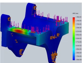
CAD MODELLING AND ANALYSISCAD Modeling is the base of any project. Finite Element software will consider shapes, whatever is made in CAD model. The model of the Front axle support is prepared by using CREO PARAMETRIC 2.0 software. Figure1, 2, 3 below shows the design of front axle support, mesh model of FAS and deflection produced after analysis
Figure-1 Design of front axle support
Figure-2 Mesh model of FAS
Figure-3 Deflection
V.
Optimization Approach
The objective of optimization technique is to minimise the mass of the front axle support and reduces the cost of production. The front axle support is subjected to tensile load on the upper span of the bracket while using factor of safety of around 2.0 maximum stress of front axle support is monitored and it is not over the allowable stress. The load acting on the span of it is around 20KN. The optimization technique methodology flowchart is shown in fig 6.
Figure-4 Optimization process chart
VI.
Optimization Of Front Axle Sopport
Shree Dewangan et al Int. Journal of Engineering Research and Applications
www.ijera.com
ISSN: 2248-9622, Vol. 4, Issue 4(Version 6), April 2014, pp.70-73
www.ijera.com 72 |P a g e of front axle support. The result of shape optimization
of front axle support is shown in fig 6. The main objective is to minimize the weight of the front axle support as well as the total production cost. The implementation of these optimizations is to find out the best design and shape of the front axle support to improve the performance and the strength especially at critical positions Figure 6 shows the positions where changes is necessary.
Figure-5
In the above figure A shows the area where there is no direct loading or any attachment is made, B shows the broader thickness which can reduce and C shows variable of thickness which can be optimized. After optimization following results were obtained as below.
Figure-6
In above figure A-C shows the optimization of original shape to final optimized shape.
Figure-7 Deflection after analysis
Table 3 shows the comparison between initial and optimize designs on maximum principles stress and mass of front axle support. Optimize front axle support was choose as the best optimize design due to the lowest occurred stress and mass. Even though the mass of optimized bracket is not the lowest, but the decision was also based on the maximum stress which is 196.39 MPa.
Table-3 Comparisons
S.NO. DESIGN MASS(Kg) PERCENTAGE REDUCTION
1. Original 31.28 -
2. Optimized 28.04 10.35%
VII.
Conclusions
By the finite element analysis method and the assistance of solid works software, it is able to analyze for stress and strain. In this study we tried to simulate real condition by notice to all of effective force on front axle support. Shape optimization were analyzed to the front axle support and according to the results, it can be concluded that the weight of the optimized design is up to 10.35% lighter and has more strength than initial design of front axle support. Material optimization approach will be considered for future research.
References
[1] Ritesh Kumar Dewangan, Manas Patnaik, Narendra Yadav/ International Journal of Engineering Research and Application (IJERA) ISSN: 2248-9622 vol.2, Issue 4 July-August 2012, pp.457-460
Shree Dewangan et al Int. Journal of Engineering Research and Applications
www.ijera.com
ISSN: 2248-9622, Vol. 4, Issue 4(Version 6), April 2014, pp.70-73
www.ijera.com 73 |P a g e method, Journal of Basic and Applied
Sciences. 3(2): 1438-1449.
[3] Vinod Kumar Verma, Dinesh Redkar, Arun Mahaja, HTC 2012. Weight optimization of front axle support by optistruct technology application.
[4] Rahman, M.M., Ariffin, A.K., Abdullah, S., Noor, M.M., Bakar, R.A. and Maleque, M.A. 2008b. Finite element based fatigue life prediction of cylinder head for two-stroke linear engine using stress-life approach. Journal of Applied Sciences, 8(19):3316-3327.
[5] Rahman, M.M., Ariffin, A.K., Jamaludin, N. and Abdullah, S. 2007. Effect of nitrating treatment on fatigue life for free piston linear engine component using frequency response method: a finite element approach. Structural Durability and Health Monitoring, 3(4): 197-209.
[6] Mirehei, A Zadeh, H.M., Jafari, A. and Omid M.2008. Fatigue analysis of connecting rod of universal tractor through finite element method (ANSYS).Journal of Agricultural Technology. 4(2): 21-27.Rahman, M.M., Ariffin, A.K., Abdullah, S.,Noor, M.M.and Bakar, R.A. 2009b. [7] Finite element based fatigue life prediction
of a new free piston engine mounting.
Journal of Applied Sciences, 8(9):1612-1621.
[8] Rahman, M.M., Ariffin, A.K., Rejab, M.R.M.,Kadirgama, K., Noor, M.M. 2009c. [9] Multi axial fatigue behavior of cylinder head
for a free piston linear engine” Journal of Applied Sciences, 9(15): 2725 - 2734. [10] Rahman, M.M., Kadirgama, K., Noor,
M.M., Rejab, M.R.M. and Kesulai, S.A., 2009a, Fatigue life prediction of lower suspension arm using strain life approach, European Journal of Scientific Research. 30(3): 437-450.
[11] Rasekh, M., Asadi, M.R., Jafari, A. and herald pour, K. 2009. Obtaining maximum stresses in different parts of tractor (MF-285) connecting rods using finite element method, Journal of Basic and Applied Sciences. 3(2): 1438-1449.
[12] Shenoy, P.S and Fatemi, A. 2005. Connecting rod optimization for weight and cost reduction, SAE Technical Paper, Paper No. 2005- 01-0987.