Journal of Engineering Science and Technology Review 7 (5) (2014) 40-42 Special Issue on Simulation of Manufacturing Technologies
Conference Article
Computer
Ο
ptimization of Geometric Form of Tool and Preform for Closed-die
Forging of Compressor Blade Simulator
A. V. Botkin, A. A. Kublikova*, E. V. Varenik and V. V. Astanin
Ufa State Aviation Technical University, Ufa, Russian Federation
Received 12 September 2014; Accepted 20 September 2014
___________________________________________________________________________________________
Abstract
Using the software package DEFORM 3D when developing technology of isothermal forging workpiece blades it is possible to reduce the pre-production time, to improve the quality of forgings and increase lifetime of forging dies. Computer modeling allows to predict the formation of such defects during forging as notches and wrinkles, underfilling of die impression, to estimate tool loads. Preform shape and angular position of the blade simulator were optimized in order to minimize the lateral forces generated during the forging operation.
Keywords: computer optimization; computer modeling; isothermal forging
__________________________________________________________________________________________
1. Introduction
Compressor blades have a complex shape, requiring an integrated approach in forging design and die tooling fabrication [1]. The CAD software SolidWorks allows the design of three-dimensional parametric associative mathematical models and creates associated drawings based on the models developed. The program provides integration of the product cycle creating from design to pre-production and finally to production. As a CAE system of process modeling DEFORM 3D allows the significant reduction of expenses and time of developing new forgings using the virtual process modeling of forging without die tooling production and actual loading of the presses. These two systems together form an integrated system of development of geometrically-complex forgings made of different materials [2].
The purpose of this paper is demonstrate the application of this computing technology to forging in the case of a blade blank with optimized tool loads by choosing the appropriate geometric shape of the tool and the preform.
2. Material and research procedure
A cylindrical billet with a diameter of 50 mm and length of 145 mm is chosen as the object of the present research. The material used for the workpiece is heat-resistant aluminum alloy Al-5.3Cu-0.8Mg-0.5Ag-0.3Mn-0.15Zr.
A geometrical model of the blade is shown in Fig. 1 which is used as input to design the blade forging with allowance for machining, lapping and manufacturing pad. Fig. 2 shows the forming stages of the blade manufacturing process. In the blade manufacturing process there are two major stages during forming, namely the extruding and forging stages.
(a) (b)
Fig. 1. Model of blade
Computer modeling of the isothermal closed-die forging of the blade simulator was carried out during the study using Deform 3D.
For the computer model the following conditions and assumptions were used:
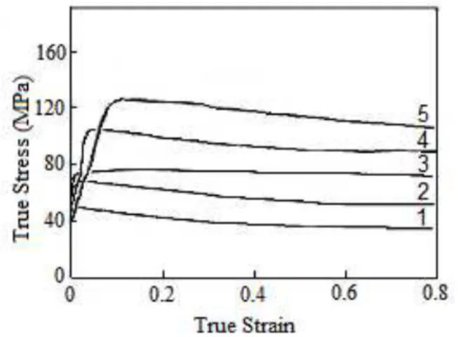
• The billet from Al–Cu–Mg–Ag alloy was plastic; hardening curves (Fig. 3) [3] were obtained with hot compression at different strain rates and were entered into the database as a table function;
• Punch, die and frame were assumed as rigid (3D models of forging tool and workpiece were designed with SolidWorks);
• The forging tool and the workpiece were heated up to 420ºC;
• Thermal effect of deformation was neglected due to low strain rate;
• The friction coefficient between the forging tool and workpiece was taken as 0.3 as suggested by DEFORM 3D;
J
estr
JOURNAL OF Engineering Science andTechnology Review
www.jestr.org
______________
* E-mail address: [email protected]
A. V. Botkin, A. A. Kublikova, E. V. Varenik and V. V. Astanin / Journal of Engineering Science and Technology Review 7 (5) (2014) 40 - 42
41 The number of elements used for the workpiece was 100,000;
• The displacement speed of the punch was 2 mm/s; • Time increment 0.1 s;
• The number of analysis steps was 300.
Fig. 2. The blade manufacturing process
One of the optimization stages is to determine the geometric shape of the preform produced by extrusion. This geometry should be input to the modeling software module to simulate the final forging operation without notches and metal wrinkles. The determination of such shape is complex due to the volume of the body of the blade forms only the third part of the volume of whole preform and the metal flow from the bottom zone would be more intensive leading to wrinkling. Computer modeling was used to solve this problem and to obtain the optimum geometric shape of the preform.
The optimum geometric shape of the preform is determined by the following algorithm: 1) determine the volumes of the body of the blade and shoe; 2) design conical part of the preform based on the diagrams of the cross sections of the blade; 3) design the transition radius from the conical part to the shoe with different values as the volume of the shoe changes; 4) carry out computer models with various transition radii from the conical part to the shoe to determine the preform shape.
Fig. 3. True stress-strain curves of the Al-Cu-Mg-Ag alloy during compression at 420°C: (1) ε 0.001s−1;
=
! (2) ε 0.01s−1;
=
!
(3) ε=0.1s−1;
! (4) ε=1.0s−1;
! (5) ε=10s−1.
!
Another optimization stage is the investigation for an angular positioning of the blade simulation forging design so to minimize tool loads. It has been assumed that the minimum tool loads during the final operating step (forging) will be reached when the left end of the body of the blade is placed on one horizontal with the right bottom vertex of the shoe on the plane view (Fig. 1a) . Taking all these into account, it was decided to investigate several angles (α) of blade rotation about the Z axis (Fig. 1b) during forging relative to the blade position. The range studied was from 19° to 40°.
A. V. Botkin, A. A. Kublikova, E. V. Varenik and V. V. Astanin / Journal of Engineering Science and Technology Review 7 (5) (2014) 40 - 42
42
3. Modeling results
Fig. 4 illustrates the filling of the die for various transition radii from the conical part of the preform to the shoe, and also on the shoe geometry. According to Fig. 4(a) the shape of the perform shoe closest to the shape of the final forged shoe doesn’t satisfy the forming condition of no notches and wrinkles as there are counter flows of metal from the shoe zone and the conical part of the preform. In order to avoid such a phenomenon, it is necessary to carefully consider a specially constructed part of the preform such as the transition radius from the conical part of the preform to the shoe. When comparing the preforms in Figs. 4(c) and 4(e) unequal metal flow is observed for identical transition radii, but different shoe geometry (Figs. 4(d) and 4 (f)-(h)). Apparently from Figs. 4 (f)-(h), the transition radius (R) of 40 mm and the compact shoe form (B=71 mm) provide filling of the die without notches and wrinkles during closed-die forging of the blade during modeling.
It is known that such a modeling parameter as mesh density significantly affects calculations. Therefore, by changing density mesh (70,000 and 150,000 elements) additional analyses were performed for the optimum preform shape, which showed a filling pattern of the die similar to the filling pattern of 100,000 elements.
To identify the optimum angular position of the blade in a closed-die forging, so that the tool loads would be minimal, the graph of the maximum tool load versus rotation angle was calculated (Fig. 5). The tool load is the projection of the forging force on a plane perpendicular to the axis along which the punch moves (the OY axis). The smaller projection value corresponds to a smaller tool load and will achieve the higher wear resistance and forging quality.
Fig. 5. Maximum tool load for various rotation angles of blade
Fig. 5 illustrates that the minimum tool load is observed at a rotational angle of the blade about the Z axis of 34°. Thus, the assumption that the minimum tool loads during the final operating step (forging) will be observed at a positioning of the left end of the blade body on one horizontal with the right bottom vertex of the shoe on the plane view was not correct. It should be noted that by changing the angular position of the blade we obtained forgings with different volumes, and value of overlaps formed by the straightening of the surfaces adjacent to the frame was changed. According to this a rotation angle of 34° is not optimal.
4. Conclusions
Computer modeling enabled to find the optimum shape of the preform with a transition radius (R) of 40 mm and the compact shoe form (B=71 mm) which fills the die without notches and wrinkles during a closed-die forging of the blade.
The angular position of the blade during forging design with rotational angle (α) of 34° about the Z axis relative to the blade position concerning the compressor axis provides the minimum tool loads generated during the closed-die forging of the blade.
The results obtained in this work were taken into account when the dies were designed.
Acknowledgements
This work was produced during the joint project between USATU (Ufa State Aviation Technical University) and UMPO (Ufa Engine Industrial Association) with title “Elaboration and industrial development of high-precision shaping coordinated technologies and superficial hardening of responsible details from Al-alloys with heightened constructional energy efficiency”, implemented under the contract №40/10-30976 sponsored by the Ministry of Education and Science of the Russian Federation (contract №02.G25.31.0010 between UMPO and the Ministry of Education and Science of the Russian Federation) through the Resolution of the Russian Federation Government № 218 from April 9, 2010.
______________________________ References
[1] V. Alimirsaloo, M. H. Sadeghi and F. R. Biglari, Optimization of the forging of aerofoil blade using the finite element method and fuzzy-Pareto based genetic algorithm, Journal of Mechanical Science and Technology. 26 (6) (2012) 1801-1810.
[2] R. A. Kazakov, Modeling of isothermal forging of gas turbine compressor blade, Forging-stamping production. 5 (2011) 39-42. [3] Xiao Yan Liu, Qing Lin Pan, Yun Bin He,Wen Bin Li,Wen Jie