E
NERGY AND
E
NVIRONMENT
Volume 2, Issue 2, 2011 pp.247-254
Journal homepage: www.IJEE.IEEFoundation.org
Analysis and performance of high efficiency synchronous
reluctance machines
M. Nagrial, J. Rizk, A.Hellany
University of Western Sydney, School of Engineering, Power Conversion and Intelligent Motion Control Group, Locked Bag 1797, Penrith South DC, Australia.
Abstract
A series of new solid rotor reluctance machines have been proposed to achieve high saliency ratio. It is shown that proper distribution of magnetic and non-magnetic materials can result in improved performance. The saliency ratios and configurations of experimental machines are also given. The solid rotor design is attractive from manufacturing point of view. The paper discusses the analysis, performance and design aspects of reluctance motors. The design and performance of a series of experimental machines is also given.
Copyright © 2011 International Energy and Environment Foundation - All rights reserved.
Keywords: Synchronous reluctance machines, Variable reluctance machines.
1. Introduction
Reluctance or variable reluctance motors have been known as early as induction motors. Due to their rather poor performance, they were ignored during the earlier part of the 20th century except for special applications. In the early sixties and seventies, synchronous reluctance motors were extensively investigated as line-start synchronous motors and new configurations emerged, [1-11]. Though, the general performance of these new designs were much better and quite comparable with induction motors in many aspects but it did not result in wide spread use of these motors. Due to recent developments in power electronic devices, converters and control techniques, reluctance motors have emerged as general and high performance industrial drives for variable speed applications, [12-17]. This has given the designers an opportunity to revisit the electromagnetic design of such motors and optimise the configuration. Several efforts have been made to identify practical rotor structures, which have high saliency ratios [19-27]. The stator of such machines is similar to a standard polyphase AC motor with conventional winding. The modern reluctance motors are inverter driven and hence do not require starting cage windings. This has given the designers a flexibility to optimise the magnetic circuit. The reluctance drive systems can be driven as a brushless drive with a position sensor or speed sensorless and also operate as synchronous motor in open loop mode without position sensor [12-14].
employ laminated rotors but unlaminated designs can be very attractive due to ease manufacturing [8,19]. A converter fed reluctance motor is a promising candidate for variable-speed drive applications [12,13]. The present paper is devoted to the analysis and design of cageless synchronous reluctance motors, employing solid rotor rather than laminated construction. A solid rotor design can withstand high operating speeds and further so due to absence of permanent magnets. In earlier designs, various configurations have been proposed, e.g. salient poles, axially laminated, semi-pole, segmented, flux-barrier or flux-guided designs, even asymmetrical designs [1-8]. New research interest in synchronous reluctance drives is focused mostly either on flux guided or axially laminated or a combination of both. It has been due to obvious advantages in performance and commercial manufacturing.
2. Analysis and performance
The principle of operation of reluctance synchronous machines (RSMs) is based on existence of variable reluctance in the air gap of the machine, high reluctance in the quadrature axis and low reluctance in the direct axis. It is now well known fact that RSM output increases with high Xd and low Xq (i.e. high
Xd/Xq). The reluctance synchronous motor runs at synchronous speed, once synchronised, irrespective of
variation in supply voltage or load. All the attempts to improve the performance are centred on modifications to the rotor magnetic circuit so as to achieve a high Xd/Xq, while the stator is similar to a
standard 3-phase AC motor.
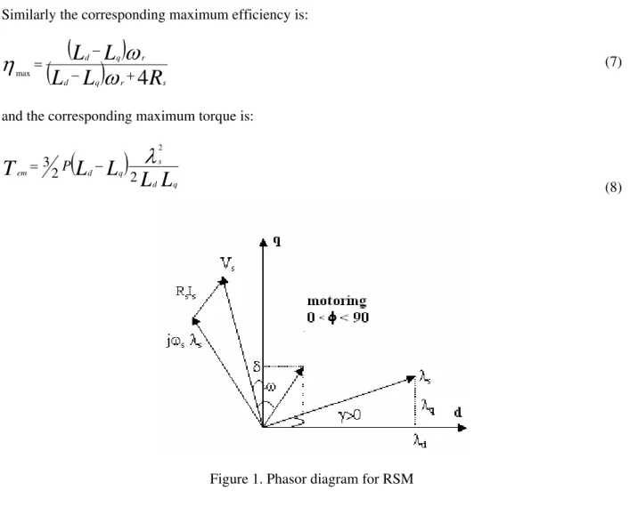
The analysis of RSM can be attempted by using the d-q model of machine. Figure 1 shows the phasor diagram for a RSM for motoring operation [15-18].
i
L
di
L
i
R
V
r d qd d d s
d= + dt −
ω
(1a)i
L
di
L
i
R
V
r d dq q q s q
dt +
ω
+
= (1b)
and the torque
(
L
L
)
i
i
T
e= 2P d− q d q3 (2)
where P = number of pole pairs.
The developed power in the machine, neglecting copper and iron losses, can be written as:
(
)
( )
L
L
V
L
L
T
P
q d r s q d r e e Pω
ω
12 sin2δ2 3
2
− =
= (3)
The power factor of the machine can be defined as:
i
V
P
P
P
s s iron co e 2 3cosφ= + + (4)
and the efficiency, neglecting mechanical losses, can be represented as:
P
P
T
T
iron co r e r e P P + + = / /ω
ω
η (5)
The above equations can be further developed to obtain maximum power factor, maximum efficiency and maximum torque and they are given by the following, rather simplified equations.
The maximum power factor is:
( )
1 1 cos max + − = + − =L
L
L
L
L
L
L
L
q d q d q d q dSimilarly the corresponding maximum efficiency is:
(
)
(
L
dL
L
q)
L
rR
s r q d4
max − +
− =
ω
ω
η
(7)and the corresponding maximum torque is:
(
)
L
L
L
L
T
q d
s q d
em P
2 2
3
2
λ
− =
(8)
Figure 1. Phasor diagram for RSM
The performance of reluctance synchronous motor depends on saliency ratio or
q d L L
=
λ with both high Ld
and (Ld-Lq), the inductance difference. The classical expression (equation 2) for air gap torque can be
rewritten as follows:
)
2
(
sin
2
)
(
L
L
m
pI
2δ
I
mpI
T
=
d q d−
q=
(9)where
m = Number of phases
p = Number of pole pairs
Ld = Direct axis synchronous inductance
Lq = Quadrature axis synchronous inductance
δ = Torque or load angle
The air gap torque or power per ampere is directly related to the difference in q–axis and d-axis inductances. In general the performance is improved as λ is increased. The power factor is related to saliency ratio (λ) as follows:
)]
cot
(tan
2
/[
)
2
sin(
)
1
(
)
(
cos
φ
=
λ
−
δ
δ
+
λ
2δ
(10)The power factor has a maximum value of:
)
1
(
/
)
1
(
)
(
A high saliency ratio (λ) is desirable to achieve a high power factor. The above equations look rather simple. The reluctance motor is generally saturated compared to an equivalent induction motor due to removal of magnetic material from the rotor. The direct axis inductance Ld is not constant and can vary
appreciably while the quadrature axis inductance Lq is generally constant due to high reluctance path.
3. New rotor designs
Most of the electrical machines are manufactured using laminated construction to reduce magnetic losses, including reluctance motors. As mentioned earlier, a reluctance motor has to have some form of saliency (different reluctance in direct and quadratic axis). The stator is similar to an AC motor stator with slots for windings but considered a smooth cylinder with allowances for slot openings, i.e. Carter’s factor. It can be achieved by removing magnetic materials either from the surface or inside the rotor [5-7] or axially laminated design with insulation material sandwiched between the lamination [3, 4]. It is generally accepted that a simple salient pole design does not produce high saliency ratio and rarely employed in modern reluctance machines.
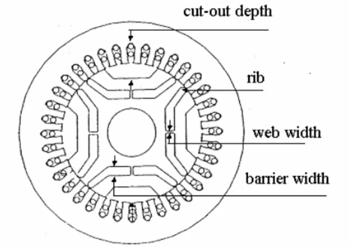
The present investigation is focussed on flux barrier or flux guided designs with single and multiple flux-barriers. Although, high saliency ratios are achievable with axially laminated design but it is rather expensive and difficult to manufacture. It is possible to achieve high saliency ratios with flux barrier or flux-guided designs provided flux barriers have optimum dimensions and locations. To achieve one piece lamination and ease of fabrication, the flux barrier rotor is provided with ribs or bridges as shown in Figure 2.
These ribs or bridges provide an ideal flux path for quadrature axis flux although; the rib section becomes highly saturated at high flux levels. The thinner the rib section, the better it is for saliency ratio. A thinner rib section can also decrease the mechanical strength of the rotor and the rotor needs to be strengthened by other mechanical means. The present investigation is focussed on the development of high performance reluctance motors employing solid iron pieces rather than laminated designs. The solid rotor pieces can be easily assembled and hence magnetic bridges or ribs can be dispensed with. By removing magnetic ribs, the reluctance of the quadrature axis can further be increased, thus further reducing quadrature axis inductance.
Figure 2. Reluctance machine flux-guided rotor with magnetic bridge
4. Experimental machines
Figures 3(a)-3(d) show some of the experimental rotors, designed and fabricated to assess their performance. Figure 3(a) shows a single flux barrier rotor, while Figures 3(b), 3(c) and 3(d) show two flux barriers, three flux barriers and five flux barriers rotors respectively. As mentioned earlier, the basic criteria for a good design is to have a high saliency ratio (Ld/Lq) accompanied by a high (Ld-Lq), i.e. a
high Ld and low Lq. Finite element package is employed to compute the flux distribution and
Table 1 summarises the saliency ratios (Ld/Lq) of the four machines. It can be seen that by increasing the
number of flux barriers, the saliency ratio has increased. This is due to the fact that proper arrangement of insulation and magnetic material in the rotor can result in high saliency ratio and not the amount of insulation and magnetic material. It is worth mentioning that the amount of magnetic material is kept the same with all the different designs. The designs can further be optimized by asymmetrical distribution of magnetic material and non-magnetic spaces.
Figure 3. Experimental solid rotor reluctance machines
Table 1. Ld, Lq, Ld/Lq of Solid Rotor Reluctance Machines
Unsaturated
Machine Ld(H) Lq(H) Ld/Lq
1FG/Pole 0.748 0.245 3.05
2FG/Pole 0.995 0.202 4.925
3FG/Pole 0.963 0.151 6.377
5FG/Pole 1.0804 0.12 9.03
Saturated
1FG/Pole 0.258 0.17 1.51
2FG/Pole 0.352 0.158 2.28
3FG/Pole 0.393 0.121 3.25
5FG/Pole 0.483 0.107 4.51
c) 3 Flux-guided RSM
b) 2 Flux-guided RSM
It can be seen that increasing the number of flux guides or barriers has resulted in high Ld/Lq. A large
number of flux-guides or barriers result in rather optimum distribution of magnetic and non-magnetic materials in the rotor. The ratio Ld/Lq as a function of applied voltage is shown in Figure 4. Figure 5
shows Ld and Lq as a function of current
Figure 4. Ld/Lq for 5FG, 3FG, 2FG and 1FG
Figure 5. Ld and Lq for 5FG, 3FG, 2FG and 1FG
The experimental performance of these machines has also been improved considerably compared with induction machines. It can also be seen that the direct axis inductance Ld has reduced considerably while
Lq is not reduced in the same proportion as the machines are driven into saturated region. A 3
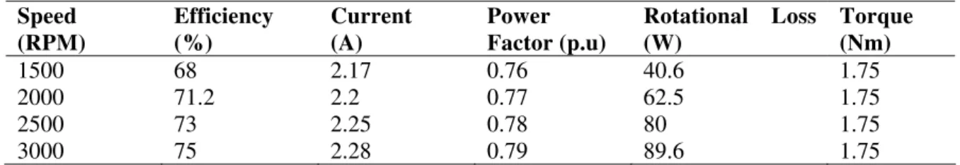
flux-guided design can be acceptable for such low power motors from manufacturing point of view and reasonably high performance as a variable speed motor. These machines are driven as variable speed drive systems. Table 2 summarises the experimental performance of 3 flux-guided reluctance motors at various speeds and rated torque.
Table 2. Experimental performance of 3 flux-guided reluctance motor
Speed (RPM)
Efficiency (%)
Current (A)
Power Factor (p.u)
Rotational Loss (W)
Torque (Nm)
1500 68 2.17 0.76 40.6 1.75
2000 71.2 2.2 0.77 62.5 1.75
2500 73 2.25 0.78 80 1.75
3000 75 2.28 0.79 89.6 1.75
0 2 4 6 8 10
0 100 200 300 400 500
V, v
Ld/
Lq
5FG
2FG
1FG
3FG
0 0 . 2 0 . 4 0 . 6 0 . 8 1 1 . 2 1 . 4
0 0 . 5 1 1 . 5 2 2 . 5 3
I , A
Ld
,Lq
(
H
)
5. Conclusion
A series of experimental reluctance machines, with solid rotor design has been proposed. These designs are of flux-guided or flux-barrier types. The designs are based on an equivalent 2-pole, induction motor of 550-w rating. It is shown that proper distribution of magnetic and non-magnetic materials can result in high saliency ratio and also high (Ld-Lq), a pre-requisite for improved performance. The inductances and
the performance of one such machine is also given when driven as a variable speed drive.
References
[1] Lawrenson, P.J. and Agu, L.A. Theory and Performance of Polyphase Reluctance Machines. Proc. IEE, 111(8), pp. 1435-1445, 1964.
[2] Lawrenson, P.J. and Gupta, S.K. Developments in the Performance and Theory of Segmental-rotor Reluctance Machines. Proc. IEE, 114(5), pp. 645-653, 1967.
[3] Cruickshank, A.J.O., and Menzies, R.W. and Anderson, A.F. Theory and Performance of
Reluctance Motors With Axially Laminated Anisotropic Rotors. Proc. IEE, 118(7), pp. 887-894, 1971.
[4] Cruickshank, A.I.O. and Menzies, R.W. “Axially laminated anisotropic rotors for reluctance motors”. Proc. IEE, vol. 113, 1966, pp. 2058 – 2060.
[5] Honsinger, V.B. Steady State Performance of Reluctance Machines. IEEE Trans PAS-90, pp. 305-311, 1971.
[6] Honsinger, V.B. The Inductance Ld and Ld of Reluctance Machines. IEEE Trans PAS-90, pp.
298-304, 1971.
[7] Fong, W. And Htsui, J.S.C. New Type of Reluctance Motor. Proc. IEE, 117(3), pp. 545-551, 1970. [8] Chalmers, B.J. and Mulki, A.S. Design and Performance of Reluctance Motors with Unlaminated
Rotor. IEEE Trans, PAS-91, No. 4, pp. 1564-1569, 1972.
[9] Finch, J.W. and Lawrenson, P.J. Synchronous Performance of Single-phase Reluctance Motors. Proc. IEE, Vol. 125(12), pp. 1350-1356, Dec., 1978.
[10] Hasan, S.A. and Osheiba, A.M.F. and Mohamadein, A.L. Performance of different types
reluctance motors, experimental comparative study. Electric Mach & Electromechanics, Vol. 5, pp. 225-236, 1980.
[11] Nagrial, M.H. Large reluctance motors design: a non-linear programming approach. Computers & Elect. Eng., Vol 8, pp. 283-288, Dec., 1981.
[12] Vagati, A. The synchronous reluctance solution: A new alternative in AC drives, IEEE, pp. 1-13, 1994.
[13] Lipo, T.A. Synchronous Reluctance Machines: A viable alternative for AC drives. Electric Machines and Power Systems, pp. 659-671, 1991.
[14] Boldea, I. Emerging Electric Machines with axially laminated anisotropic rotors: A review. Electric Machines and Power Systems, pp. 673-703, 1991.
[15] Naser, S. A. , Boldea I. & Unnewehr L. E. “Permanent magnet, Reluctance and self synchronous motors”.CRC Press, Boca Raton, 1993.
[16] Boldea I. “Reluctance synchronous machines and drives”; Clarendon Press; 1996
[17] Nagrial, M.H. and Sadri, S.M.R. Design and performance of axially laminated cum flux-guided reluctance motor. Proc. Australasian Universities Power Engineering Conference (AUPEC ‘95), pp 65-71, Perth, W.A., Sept., 27-29, 1995.
[18] Nagrial, M.H. “Developments of Sensorless Synchronous Reluctance Drive Systems” IEEE
Conference- INMIC- Lahore Pakistan, Dec 28-30, 2001
[19] Staton, D.A.; Soong, W.L.; Miller, T.J.E.”Unified theory of torque production in switched reluctance and synchronous reluctance motors” Industry Applications, IEEE Transactions on Volume 31, Issue 2, Mar/Apr 1995 Page(s):329 – 337
[20] Kamper, M.J.; Van der Merwe, F.S.; Williamson, S. “Direct finite element design optimisation of the cageless reluctance synchronous machine” Energy Conversion, IEEE Transaction on Volume 11, Issue 3, Sep 1996 Page(s):547 – 555
[21] Isaac, F.N.; Arkadan, A.A.; El-Antably, A “Characterization of axially laminated anisotropic-rotor synchronous reluctance motors” Energy Conversion, IEEE Transaction on Volume 14, Issue 3, Sep 1999 Page(s):506 – 511
[23] Chabu, I.E.; Cardoso, J.R.; Silva, V.C.; Nabeta, S.I.; Foggia, A. “A new design technique based on a suitable choice of rotor geometrical parameters to maximize torque and power factor in synchronous reluctance motors. I. Theory” Energy Conversion, IEEE Transaction on Volume 14, Issue 3, Sep 1999 Page(s):599 – 604
[24] Chabu, I.E.; Cardoso, J.R.; Silva, V.C.; Nabeta, S.I.; Foggia, A. “A new design technique based on a suitable choice of rotor geometrical parameters to maximize torque and power factor in synchronous reluctance motors. II. Finite-element analysis and measurements” Energy Conversion, IEEE Transaction onVolume 14, Issue 3, Sep 1999 Page(s):605 – 609
[25] Arkadan, A. A.; Hanbali, A. A.; Al-Aawar, N. “Design Optimization of ALA Rotor SynRM
Drives Using T-AI-EM Environment” Magnetics, IEEE Transactions onVolume 43, Issue 4, April 2007 Page(s):1645 – 1648
[26] Ki-Chan Kim; Joon Seon Ahn; Sung Hong Won; Jung-Pyo Hong; Ju Lee “A Study on the Optimal Design of SynRM for the High Torque and Power Factor” Magnetics, IEEE Transactions on Volume 43, Issue 6, June 2007 Page(s):2543 – 2545
[27] Sun Bum Kwon; Park, S.J.; Jung Ho Lee; “Optimum design criteria based on the rated Watt of a synchronous reluctance motor using a coupled FEM and SUMT”Magnetics, IEEE Transactions on Volume 41, Issue 10, Oct. 2005 Page(s):3970 – 3972
M. Nagrial obtained his Ph.D. from University of Leeds, UK. He is presently working in the School of Engineering, University of Western Sydney. He has extensive experience in Power Electronics and Drive Systems, Renewable Energy Systems. He is Co-ordinator for Research Group “ Power Conversion & Intelligent Motion Control”. He has conducted many short courses and published extensively in his area of expertise. He is a leading researcher in the area of permanent magnet & variable reluctance machines and drive systems. He has supervised many Ph.D. and M.Eng. (Hons) Research Theses and postdoctoral fellows in this area. Prof. Nagrial is a Fellow of IET (UK) and IE (Aust), and Senior Member IEEE (USA). He has acted as reviewer for grant applications, refereed papers for International Journals and Conferences and examined many Ph.D. theses in his area of expertise. He has published extensively in International Journals and delivered lectures at many international conferences.
E-mail address: [email protected]
Jamal Rizk is a member of the Research Group: “Power Conversion and Intelligent Motion Control (PCIMC)”. He has a doctorate from Kharkov Polytechnic, Ukraine and a Ph.D. from University of Western Sydney, Australia. Dr. Rizk is a Senior Lecturer in the school of Engineering and Industrial Design, University of Western Sydney. He has attended and presented results of his research at different Australian and International Conferences. Dr Rizk has developed special expertise in the magnetic analysis of different types of permanent magnet machines. He has been involved in design, fabrication and testing of electrical drives. He has also developed research interests in integrated renewable energy systems and published extensively. Dr Rizk was the postgraduate and research coordinator in the school of Engineering and Industrial Design, UWS. Dr Rizk has acted as reviewer for papers for National and International conferences.
E-mail address: [email protected]
Ali Hellany hold a BE in telecommunication, ME (Hons) in Electrical Engineering and a Ph.D in Electrical Engineering, from University of Western Sydney (Australia). Ali is a member of (International Electronics and Electrical Engineers) IEEE, Executive member of IEEE NSW Section and Charing the student activity. Ali is a member of the Electromagnetic society. Ali Hellany is a senior lecturer At the School of Engineering, University of Western Sydney since 2002. Dr Hellany has published numerous papers in the Electromagnetic Compatibility, power quality, Ac Interference, teaching styles and digital forensics area in journals and presented his research in many International conferences.