International Journal of Electronics Communication and Computer Engineering
Volume 6, Issue 2, ISSN (Online): 2249–071X, ISSN (Print): 2278–4209
Copyright © 2015 IJECCE, All right reserved
240
Comparison Between Line Start PM Synchronous Motor
and Induction Motor With Same Nominal Power and
Same Pole Pairs When Fed By VF Control Drive
Ali Reza Sadoughi
Faculty of Electrical Engineering, Malek Ashtar University of Technology,
Esfahan, email: [email protected]
Mohsen Zare
Fars Power Generation and Management Company
email: [email protected]
Mohsen Azizi
Fars Power Generation and Management Company email: [email protected]
Abstract: Given the importance of electric machines in the
industry with high efficiency, and speed control of this machines are also important, in this paper, three-phase line start permanent magnet synchronous motor and three-phase induction motors that are same in nominal power and the number of poles, is controled, monitored and compared by open-loop voltage to frequency drive, with each other. To this end, simulating the same conditions for the launch of electronic drive with open loop control V/Hz with constant
load torque is provided.Simulation results from
MATLAB/Simulink software are presented for both line-starting and Adjustable Speed Drive (ASD) applications in the same situations, to provide a comprehensive comparison, and it shows a transient and steady-state response of an LSPMSM drive compared to its IM.
Keywords: Line Start Permanent Magnet Synchronous
Motor (LSPMSM), Induction Motor, Open Loop Control V/ Hz (V/F), Electronic Drives, Adjustable Speed Drive (ASD).
I.
I
NTRODUCTIONIn recent years, the needs for high efficiency motors in various industrial products, in order to save more energy is felt. In many applications, a permanent magnet synchronous motor with a smaller but more efficient than electric machines can be designed [1].In previous years, the permanent magnet motor drive increased attention in the scientific community and industry have attracted. The performance of PM is much improved and the price has dropped. Due to the high efficiency and power factor of LSPMSM and its ability to launch a set of fixed frequency and speed adjust to the zero steady slip; to compete with cage induction motors in industrial applications has become a general purpose, LSPMSM substantially higher power factor of induction motor can operate. They are even in same or nearly the power factor one in many applications and work conditions [2, 3]. Use the LSPMSM with inverter already in wide range of applications is on the rise; There are two reasons for this trend; First, high efficiency and high power factor of
LSPMSM Second, permanent magnet price cuts
In addition LSPMSM run up from zero speed with a fixed frequency, it has become an attractive scheme for senseless drives [4]. Although originally designed solely LSPMSM motors offer the ability to startup permanent magnet synchronous motors, Remove Hardware and Electric drives and associated costs, but having high
efficiency motors and manufacturers meet energy standards too. These motors is designed comfort, only with slight changes occur in induction motors. Therefore, researchers and industrialists in recent years will focus on specific approaches to these motors so that have a unique competitor for induction motors have raised [6, 7, 8, and 9]. Because the operation of LSPMSM at a constant speed, it reduces the overall capabilities of it, the needs to exploit the LSPMSM motors electric drive are felt. In a few cases in which there are three researches has been conducted with the LSPMSM drive. In [7] is simply a senseless vector control designed only for a single-phase LSPMSM has been where the stator current vector control based on load. In [8,9] use these motors with variable speed drives (VSD) is examined. [8] analyze the characteristics of the LSPMSM in the constant torque and constant power control loop voltage and frequency are investigated. Also [10] studied the performance of electric motors with direct torque control method discussed, and it also made similar induction motor with LSPMSM, And compares its performance has not been tested at different speeds and the torque control is sufficient. Since the objective of this study is that "Efficacy of the induction motor and LSPMSM with similar power rate and poles number" In terms of connectivity is designed to drive, still have not found that this issue be examined. And in articles about LSPMSM, induction motors with frame size has been changed to LSPMSM that the stator windings and stator winding parameters are similar to those examined. After an induction motor with a nominal power specified for replacement with a similar LSPMSM away the power industry is required.
The similarities and differences of these two types of motor rated current and the nominal values of parameters are different frames, to know. In this paper we examine the equations of three-phase LSPMSM and induction motor then using the software Matlab / Simulink as a simulation tool, three-phase LSPMSM with a power rating of 1.1 kW and 4 poles compare with the same three phase induction motor with a power rating of 1.1 kW and 4 poles when drive by inverter under constant load torque and constant power region (flux weakening).
II.
I
NDUCTIONM
OTORM
ODELCo rotor dq reference frame [11]. The equa rotor voltages are described as follows:
+ = + − = + + = r s r s s r s r ds r qs m r ds s r ds r qs r ds m r qs s r qs p i r V p i r V p i r V 0 0 0 λ λ λ ω λ λ ω = + = = + = = + = 0 ' ' ' ' 0 ' ' ' ' 0 ' ' ' ' 0 0 0 r r r r r r r r dr r dr r r dr r qr r qr r r qr p i r V p i r V p i r V λ λ λ
Where the d–q axis variables (Vds, V
λqs), are the stator voltage, stator curre respectively. The d–q axis rotor var current, and flux components, referred (V'dr, V'qr), (i'dr, i'qr), and (λ'dr, λ'qr),
equations of stator flux and rotor flux ca
(
)
(
)
= + + = + + = r ls r r r M r ls r r r M r ls r qs s s dr ds ds ds qr qs qs i L i i L i L i i L i L 0 0 ' ' λ λ λ(
)
(
)
= + + = + + = r lr r r r M r lr r r r M r lr r r r dr ds dr dr qr qs qr qr i L i i L i L i i L i L 00 ' '
' ' ' ' ' ' ' ' ' λ λ λ
Where rs, r'r, Lls, L'lr, and LM are th
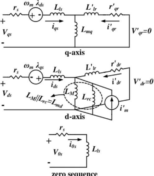
resistances and the stator leakage-, r magnetizing inductances, respectively. flux equations suggest the equivalent Figure 2. + -rs Vqs + -q-axis ωm λds
iqs i'qr
r L'lr Lls + -rs Vds + -d-axis ωm λqs
ids i'd
r L'lr Lls LM LM rs V0s + -zero sequence i0s
Lls L'lr i'0r
r
Figure 1. Rotor reference frame equival phase IM.
The mechanical equations are also ex
Copyright © 2015 IJECCE, All right reserved
241
quations of stator and s:
(1)
(2)
Vqs), (ids,iqs), and (λds,
rrent, and stator flux, variables of voltage, red to stator side, are ), respectively. The can be expressed as:
(3)
(4)
the stator and rotor , rotor leakage-, and ly. The voltage and nt circuits shown in
V'qr=0 qr
r'r
dr
r'r
V'dr=0
V'0r=0
r'r
valent circuits for a
expressed as:
(
)
− − = − = m L e m r qs r ds r ds r qs e B T T dt d J i i P T ω ω λ λ 2 2 3Where ωm and P are the angu numbers, respectively. Finally, T electromagnetic and load torques, moment of inertia, respectively.
III.
LSPMSM
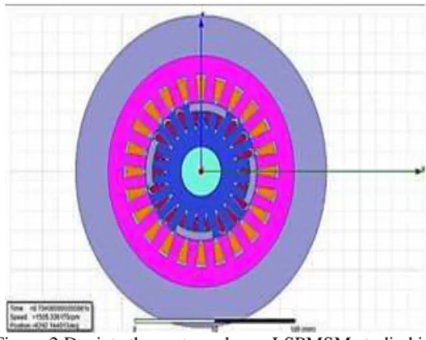
Figure 2 shows the scheme of soft Maxwell software environmen
Figure 2.Depicts the motor schem Maxwell
As described in [11] a circuit m be obtained by considering eit circuits for IM given in Figure 2 an modeling purposes, the PM in lumped and combined with the inductance of the stator (Lmd). Co d-axis magnetizing inductance den than Lmq (, i.e.,Lmd〈Lmq), and t resistance (r'qr) is smaller than th (r'dr). Besides, the equivalent mag (λ'm) is defined as:
m md m′ =L i′
λ
Where i’m the equivalent mag PM referred to the stator side. Th stator voltage, rotor voltage, stato LSPMSM are obtained as:
+ = + − = + + = r s r s s r s r ds r qs m r ds s r ds r qs r ds m r qs s r qs p i r V p i r V p i r V 0 0 0 λ λ λ ω λ λ ω (5)
ngular speed and the pole
Te, TL, B, and J are the
es, friction coefficient, and
SM
M
ODELof studied LSPMSM in An ent.
ema LSPMSM studied in ell
model of an LSPMSM can either of two equivalent and PM given in [11]. For inductance (Lrc) can be e common d-axis mutual Consequently, the resulting denoted still by Lmd is less d the resulting q-axis rotor
the q-axis rotor resistance agnetizing flux of the PM
(6)
agnetizing current of the Therefore, the equations of ator flux, and rotor flux for
International Journal of Electronics Communication and Computer Engineering
Volume 6, Issue 2, ISSN (Online): 2249–071X, ISSN (Print): 2278–4209
Copyright © 2015 IJECCE, All right reserved
242 (8)
(
)
(
)
= + + + = + + = r ls r r md r r md r ls r r r mq r ls r qs s s r m m dr ds ds ds qr qs qs i L i L i i L i L i i L i L 0 0 ' ' ' ' λ λ λ λ (9)(
)
(
)
= + + + = + + = r lr r r md r r md r lr r r r mq r lr r r r r m m dr ds dr dr qr qs qr qr i L i L i i L i L i i L i L 00 ' '
' ' ' ' ' ' ' ' ' ' ' λ λ λ λ (10)
The equivalent circuits shown in Figure 3 are obtained based on (6-10). In [11], the damper windings and notation k were used instead of the rotor windings and notation r, respectively. Furthermore, the rotor eddy-current losses in the PM material of the LSPMSM are ignored because, for instance, the value of the ohmic resistance of NdFeB-permanent magnet is 80 times larger than that of copper resistance.
+
-rs
V'qr=0 Vqs
+
-q-axis ωm λds
iqs i'qr
r'qr L'lr Lls + -rs Vds + -d-axis ωm λqs
ids
r'dr
Lls
V'dr=0 Lmq rs V0s + -zero sequence i0s Lls LM||L
rc=L md i'dr L'lr LM Lrc i'm
Figure 3. Rotor reference frame equivalent circuits for a 3-phase LSPMSM.
The electromagnetic torque of LSPMSM is expressed as [11]: ) ( 2 2 3 r ds r qs r qs r ds
e i i
P
T =
λ
−λ
(11)Clearly the flux of PM (λ'm) is laid in the parameterλrqs, and equation (11) is completely equal to (5) which is about
the IM.
The electromagnetic torque, expressed in (12), is developed into three components: a reluctance torque which is formed due to the saliency of the motor; an excitation torque which is produced thanks to the field of PM; and an induction torque which is also called asynchronous or cage torque. It is obvious that the excitation and reluctance components, caused because of the PM, are zero for an IM.
(
)
− + + − = Torque ce luc r qs r ds mq md Torque Excitation r qs r Torque Induction r ds r qr mq r qs r dr mde Li i Li i i L L ii
P T m tan Re ' ' ' 2 2
3
λ
(12)Similar IM, based on (11), the other equations such as (13) can simply be derived, which shows that the electromagnetic torque is formed by the interaction of the stator flux space vector (λS ) and stator current space
vector (iS), and equation(13) is valid for all the electrical machinery in all the reference frames.
(
S S)
S S S S e i P i PT = λ × = λ sin α −ρ
2 2 3 2 2 3
(13)
IV.
O
PENL
OOPVF
S
PEEDC
ONTROLThe open loop volts/Hz control of an induction motor is by far the most popular method of speed control because of its simplicity. For adjustable speed applications, frequency control is natural. However; voltage is required to be proportional to frequency so that the flux remains constant, negleting the stator resistance Rs drop [12].Figure 4 shows the block diagram of the volt/hertz speed control method.
Copyright © 2015 IJECCE, All right reserved
243
V.
S
IMULATIONThe major aim of this paper is LSPMSM motor performance when working with electrical drives. Therefore, it is necessary that (in order to evaluate the effect of electric drives) the performance of the motor in the case of direct connection to the line voltage is studied to ensure the accuracy of such motor.
LSPMSM motor performance when working with electric drives; so when motor speed control performance can affect the electrical drives for motors discussed and analyzed. However, in order to provide a comprehensive analysis of the impact of magnetic reluctance effect on
engine performance LSPMSM, to evaluate the
performance of the motor and comparison with induction motors with the same speed and power (under identical conditions) will be discussed. Parameters of induction motor squirrel cage (with aluminum body, the size is of 90L, making by Motogen Tabriz-Iran, 4-pole, 1/1 kW, 1400 rpm) and LSPMSM (with aluminum body, the body 80L, made in [15, 16], 4-pole, 1/1 kW, 1500 rpm) is shown in Table 1. LSPMSM and flux permanent magnet motor parameters (λ'm = 0.9033) according to the design and construction in [13, 14] in order to achieve good efficiency and power factor close to the unit at nominal conditions is considered.Power system parameters include parameters of three-phase voltage source inverter; rectifier and DC link voltage is monitored in accordance with the appropriate components for the drive in Table 2 is shown.
It is worthwhile to note that the following assumptions are considered to model these machines.
• The magnetic saturation, skin effects, and core losses are neglected.
• The stator windings and rotor bars are assumed as windings with a sinusoidal distribution.
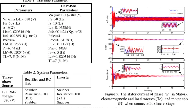
Table 1. Machine Parameter IM
Parameters
LSPMSM Parameters
Vn (rms L-L)=380 (V) Fn=50 (Hz)
rs=8(Ω)
Lls=0. 020546 (H) J=0. 002385 (Kg. m^2) Poles=4
LM=0. 3522 (H) r'r=6. 44 (Ω) Llr'=0. 020546 (H) TL=7. 5 (N. M)
Vn (rms L-L)=380 (V) Fn=50 (Hz)
rs=10 (Ω) Lls=0. 0358(H) J=0. 001424 (Kg. m^2) Poles=4
Lmq=0. 3103(H) Lmd=0. 1187 (H) λ'm=0. 9033 r'r=8. 5 (Ω) Llr'=0. 020546 (H) TL=7 (N. M)
Table 2. System Parameters
Three-phase Source
Rectifier and DC link
Inverter
L-L RMS voltage= 380 (V)
Snubber Resistance=100 (KΩ)
Snubber
Snubber Resistance=100 (KΩ)
Snubber
capacitance= 2 (nF)
capacitance= inf
Phase angle of phase A= 0 (Degree)
Device=Diode On-State Resistance=1 (mΩ)
Device=IGBT/Diode On-State
Resistance=1 (mΩ) [rise-, fall] time=[0.5,1.5] (us)
Frequency= 50 (Hz)
DC-Bus
Capacitance=1360 (uF)
Forward voltage= 1.3 (V)
Forward voltages [ IGBT Vf, Diode Vfd]=[1.8, 2.5](V)
In order to simulate a microcontroller, 15.6 kHz switching frequency is selected and the system with discrete steps of 2 microseconds in MATLAB / Simulink simulation.
A. Simulation results of Line-fed conditions of
constant torque load
Although the different squirrel-cage and PM materials, the different load torque and inertia, the different voltage, and the different frequency of input supply cause to yield different steady-state and dynamic line-starting transients, the simulation results for the aforementioned IM and LSPMSM, supplied by the mains, and load torque equal to 7 N.M (nominal torque of LSPMSM)for only Line-to-Line (L-L) input voltage 380 (V) and input frequency 50 (Hz) are presented. For line-starting application of both IM and LSPMSM, the stator current of phase "a" (ia Stator), electromagnetic torques (Te), and motor speed (N) are shown in Figure 5.For better performance evaluation, dynamic and steady-state information about speed, torque and current parameters such as overshot, settling time, rise time, and steady-state speed as long as peak-to-peak (P-P) of the stator current in both transient and steady states based on Figure 5 are listed in Table 3 and Table 4.
Figure 5. The stator current of phase "a" (ia Stator), electromagnetic and load torques (Te), and motor speed
(N) when connected to line voltage
0 0.5 1 1.5 2 2.5 3
-20 -10 0 10 20
Ia
S
ta
to
r
IM LSPMSM
0 0.5 1 1.5 2 2.5 3
-500 0 500 1000 1500 2000
N
(r
p
m
)
0 0.5 1 1.5 2 2.5 3
-10 0 10 20 30
T
o
rq
u
e
(N
.M
)
time(Sec) 0.05 0.1 0.15
-20
-100
10
2.8 2.9
-4 -20 2 4
0.1 0.2 0.3 0.4
1400 1600 1800
2.85 2.9 2.95
1400 1450 1500 1550
0.05 0.1 0.15
-100
10 20
2.8 2.85 2.9 2.95
6.57
International Journal of Electronics Communication and Computer Engineering
Volume 6, Issue 2, ISSN (Online): 2249–071X, ISSN (Print): 2278–4209
Copyright © 2015 IJECCE, All right reserved
244
Figure 6. Torque –Speed curve, induction motor and LSPSMSM in Line fed connection
Table 3. Transient and steady-state data obtained from simulations Line fed for both motors (Figures 5).
Machine Steady State
Overshot Rise time (sec)
Settling time (sec)
Speed (RPM)
IM 1433 60 0.056 0.25
LSPMSM 1500 340 0.132 1.13
Torque (N.M)
IM 7 20 0.0012 0.6
LSPMSM 7 20.4 0.001 1.6
Table 4. Transient and steady-state data obtained from simulations Line fed for both motors (Figures 5).
Stator Current
Machine P-P of
ia Stator in Transient
(A)
P-P of ia Stator in Steady
State(A)
IM 35.7 7.5
LSPMSM
23.1 5.52
B. The simulation results for open loop VF Drive
conditions of constant torque load
The simulation results are given in the same situations LSPMSM and induction motors connected to the drive with 750 rpm speed set point in the constant load torque equal to 5 N.M has been set up.And then in moment 0.4 seconds speed set point is 1500, and 1800 was selected at 1 second. Phase stator current of a (ia Stator), electromagnetic torque (Te) and motor speed (Nr) for induction motors and LSPMSM shown in Figure 7.
And spread of Figure 7, respectively as shown in Fig 8 to fig 10. Transient and steady-state parameters of Figures 8 to 10 are listed in Table 5 and Table 6.
Figure7. Stator current of phase "a" (ia Stator), electromagnetic (Te ), induction motor and LSPSMSM in
connection to the drive with constant torque
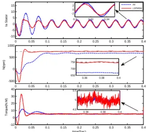
Figure 8. The extended of Figure 7 in the time interval (0-0.4) seconds (the first stage).
Figure 9. The extended of Figure 7 in the time interval (0.4-1) seconds (the second stage).
-200 0 200 400 600 800 1000 1200 1400 1600 -5
0 5 10 15 20 25 30
IM(RPM)
T
e
I
M
(N
.M
)
-500 0 500 1000 1500 2000
-10 0 10 20 30
LSPMSM(RPM)
T
e
L
S
P
M
S
M
(N
.M
)
0 0.5 1 1.5
-10 -5 0 5 10
Ia
S
ta
to
r
IM LSPMSM
0 0.5 1 1.5
-500 0 500 1000 1500 2000 2500
N
(r
p
m
)
0 0.5 1 1.5
-10 0 10 20 30
T
o
rq
u
e
(N
.M
)
time(Sec)
0 0.05 0.1 0.15 0.2 0.25 0.3 0.35 0.4
-10 -5 0 5 10 15
Ia
S
ta
to
r
IM LSPMSM
0 0.05 0.1 0.15 0.2 0.25 0.3 0.35 0.4
-500 0 500 1000
N
(r
p
m
)
0 0.05 0.1 0.15 0.2 0.25 0.3 0.35 0.4
-10 0 10 20 30 40
T
o
rq
u
e
(N
.M
)
time(Sec)
0.3 0.32 0.34 -2
0 2
0.36 0.38 0.4 650
700 750
0.36 0.38 0.4 4.5
5 5.5
0.4 0.5 0.6 0.7 0.8 0.9 1
-10 -5 0 5 10 15
Ia
S
ta
to
r
IM LSPMSM
0.4 0.5 0.6 0.7 0.8 0.9 1
500 1000 1500 2000
N
(r
p
m
)
0.4 0.5 0.6 0.7 0.8 0.9 1
-20 0 20 40
T
o
rq
u
e
(N
.M
)
time(Sec)
0.97 0.98 0.99 -2
0 2
0.95 0.96 0.97 0.98 0.99 1400
1450 1500 1550
0.9 0.95 1
Copyright © 2015 IJECCE, All right reserved
245
Figure 10. The extended of figure 10 in the time interval (1-1.5) seconds (the third stage).
Figure 11. Torque –Speed curve, induction motor and LSPSMSM in connection to the drive with constant torque
Table 5. Transient and steady-state data of speed and torque; obtained from simulations of VF drive for both
motors (Figures 8-10).
Torque Speed
Torque Ripple in
Steady-state (N.m) Settling
time (sec) Rise time (sec) Overshot
(RPM)
Steady-State (RPM) Machine
0.49 0.08 0.09 5 670 IM
Stage 1 (Figure
8) 750 85 0.03 0.35 0.55
LSPMS M
0.16 0.05 0.026 84 1436 IM
Stage 2 (Figure
9) 1500 458 0.015 0.24 0.8
LSPMS M
0.24 0.062 0.027 105 1700 IM
Stage 3 (Figure 10
1800 407 0.019 0.14 0.84
LSPMS M
Table 6. Transient and steady-state data of stator current, efficiency and power factor; obtained from simulations of
VF drive for both motors (Figures 8-10).
Efficiency and Power Factor in Stator Current
η
in
Steady-State (%) P.F. in Steady-State Magnitude
of fundamental
component in
Steady-state (A) THD
ia Stator
(%)
Peak- to-Peak
ia Stator
in its First Machine
58 0.78 3.26
2.47 18.7 IM Stage
1 (Figure
8) LSPMSM 13.3 3.03 2.67 0.89 67
74.3 0.68 3.21
1.7 29.54 IM
Stage 2 (Figure
9)
80 0.87 2.93
3.42 27.7 LSPMSM
87.13 0.81 3.34
1.56 27.4 IM Stage
3 (Figure
10
LSPMSM 39.1 5.28 2.03 0.97 97.5
VI.
D
ISCUSSIONFor Line Fed State: LSPMSM motor has outperformed the induction motor is the steady, because the motor to remove the rotor losses and eliminate all problems related to slip, resulting in improved efficiency and power factor synchronous speed, reducing current stator and the nature comes increased torque density.
In terms of dynamic braking torque on the motor block LSPMSM good dynamic performance for motor and comes LSPMSM better show the dynamic behavior of the induction motor.
For drive fed state: According to the table of steady and transient simulation in three stages, efficiency and power factor power of LSPMSM is higher than induction motor.In addition, due to lower losses, In general, you can see that for the same load torque and speed setpoint,The amplitude of the stator current pull from the VSD of LSPMSM is less than the induction motor,This parameter shows the improved torque density (torque per unit current)of LSPMSM is over than IM.LSPMSM have faster response,Of course with a speed overshoot that is greater than speed overshoot of induction motor this is because the LSPMSM moment of inertia is less And also works with zero slip. But LSPMSM torque ripple is higher than induction motor, because of the negative effect of cogging torque and velocity fluctuations are damped later than induction motor.The THD% of LSPMSM stator current is worse, and unlike induction motor with increasing frequency, THD% flow decreases.THD% of LSPMSM stator current flow increases with increasing drive frequency.And at speeds less than the rated speed during statup the first cycle of LSPMSM current is less than the first cycle of induction motor current.And at higher speeds than the rated speedduring statup the first cycle of LSPMSM current is further than the first cycle of induction motor current.Interestingly, the induction motor 1 1.05 1.1 1.15 1.2 1.25 1.3 1.35 1.4 1.45 1.5
-10 -5 0 5 10 15
Ia
S
ta
to
r
IM LSPMSM
1 1.05 1.1 1.15 1.2 1.25 1.3 1.35 1.4 1.45 1.5 1400
1600 1800 2000 2200 2400
N
(r
p
m
)
0.4 0.5 0.6 0.7 0.8 0.9 1
-20 0 20 40
T
o
rq
u
e
(N
.M
)
time(Sec)
1.46 1.465 1.47 1.475 1.48 -2
0 2
1.4 1.45 1.5
1700 1800
1.4 1.45 1.5
4 5 6
-500 0 500 1000 1500 2000
-5 0 5 10 15 20
IM(RPM)
T
e
I
M
(N
.M
)
-1000 -500 0 500 1000 1500 2000 2500
-20 -10 0 10 20 30 40
LSPMSM(RPM)
T
e
L
S
P
M
S
M
(N
.M
International Journal of Electronics Communication and Computer Engineering
Volume 6, Issue 2, ISSN (Online): 2249–071X, ISSN (Print): 2278–4209
Copyright © 2015 IJECCE, All right reserved
246
at speed setpoint equal to 750 rpmand the load of 6 N.m and more not able to startup But LSPMSM is set up and sync.
VII.
C
ONCLUSIONThe aim of current study was to evaluate the performance of three-phase LSPMSM with open loop VF drive technique in comparison to the induction motor with same power and same pole pairs. Working induction motor with improved power factor and reduce input current associated and LSPMSM to reduce power factor and increase current. LSPMSM at all times have torque ripple And % THD stator current that it undesired.
LSPMSM shows higher sensitivity than the input voltage. However, the initial current is less than the induction motor and this will result in action during the life of the motor and related equipment and is a major ad-vantage in the long run.Further research might investigate and evaluated LSPMSM performance under ASD techniques by an experimental method.
A
BBREVIATIONSLSPMSM: Line-Start Permanent Magnet Synchronous Motor
VSI: Voltage Source Inverter PWM: Pulse Width Modulation VSD: Variable-Speed Drive IM: Induction Motor PM: Permanent Magnet PWM: Pulse-Width Modulation THD: Total Harmonic Distortion PF: Power Factor
d-q axes: direct-quadratic axes RMS: Root Mean Square RPM: Rotate Per Minutes L-L: Line-to-Line P-P: Peak-to-Peak
R
EFERENCES[1] K. Kurihara, and M. Azizur Rahman, High-Efficiency Line-Start Interior Permanent-Magnet Synchronous Motors, IEEE Transactions on Industry Applications 40(2004) 789-796. [2] A. Abbas, H.A. Yousef, O.A Sebakhy, FE Parameters Sensitivity
Analysis of an IndustrialLS Interior PM Synchronous Motor, Power and Energy Society General Meeting – Conversionand Delivery of Electrical Energy in the 21st Century (2008) 1-6.
[3] T. Marcic, B. Stumberger, G. Stumberger, M. Hadziselimovic, P. Virtic, and D. Dolinar, Line-Starting Three- and Single-Phase Interior Permanent Magnet Synchronous Motors-Direct Comparison to Induction Motors, IEEE Transactions on Magnetics 44(2008) 4413 - 4416.
[4] A.H. Isfahani, and S. Vaez-Zadeh, Line start permanent magnet synchronous motors: Challenges and opportunities, Contents lists available at Science Direct Energy journal Homepage: www.elsevier.com/locate/energy, Energy 34(2009) 1755–1763. [5] D. Stoia, D. Ilea, M. Cernat, Al.B. Dezsi, A. Jimoh ,Stability of the
line-start permanent magnet synchronous motor sensorless drive, AFRICON 2007
[6] Ustun,S. V., Demirtas, M., "Optimal tuning of PI coefficients by using fuzzy-genetic for V/f controlled induction motor," Expert syst. Appl., vol. 34, no. 4, 2008.
[7] S. Taravat, A. H. Niasar and A. Rabiee Sensorless Vector Control of Single Phase Line Start Permanent Magnet Motors (LSPMs), Int. J. Sci. & Adv. Tech., vol. 2, pp. 126-131, 2012.
[8] Tine Marˇciˇc, Bojan Štumberger, Gorazd Štumberger, Comparison of Induction Motor and Line-Start IPM Synchronous Motor Performance in a Variable-Speed Drive , IEEE TRANSACTIONS ON INDUSTRY APPLICATIONS, VOL. 48, NO. 6, NOVEMBER/DECEMBER 2012Conference on Interdisciplinarity in Education ICIE (May 2009) Vilnius, Lithuani
[9] Marcic, T., B. Stumberger, G. Stumberger, M. Hadziselimovic, P. Virtic and D. Dolinar. Line-Starting Three- and Single-Phase Interior Permanent Magnet Synchronous Motors- Direct Comparison to Induction Motors, Magnetics, IEEE Trans., vol. 44, no. 11, pp. 4413-4416, 2008.
[10] Mohsen Hosseinzadeh Soreshjani,Alireza Sadoughi, Conceptual comparison of Line-Start Permanent Magnet Synchronous and Induction Machines for Line-fed of different conditions, JWEET 2014
[11] O. Chee-Mun, Dynamic simulation of electric machinery, Prentice Hall PTR, 1997.
[12] Bimal K.BoseBose, Modern Power Electronics and AC Drives, Prentice-Hall, N.J., 2002.
[13]Javad Khoshtarash Langarudi, Analysis of Application and Design of a Small Three-Phase LSPMSM by Finite Element Method in Order to Build an Elementary Prototype,M. Sc. Thesis,October 2013