UM DESCRITOR ROBUSTO E EFICIENTE DE
PONTOS DE INTERESSE: DESENVOLVIMENTO E
ERICKSON RANGEL DO NASCIMENTO
UM DESCRITOR ROBUSTO E EFICIENTE DE
PONTOS DE INTERESSE: DESENVOLVIMENTO E
APLICAÇÕES
Tese apresentada ao Programa de Pós--Graduação em Ciência da Computação do Instituto de Ciências Exatas da Univer-sidade Federal de Minas Gerais como req-uisito parcial para a obtenção do grau de Doutor em Ciência da Computação.
O
RIENTADOR: M
ARIOF
ERNANDOM
ONTENEGROC
AMPOSERICKSON RANGEL DO NASCIMENTO
ON THE DEVELOPMENT OF A ROBUST, FAST AND
LIGHTWEIGHT KEYPOINT DESCRIPTOR AND ITS
APPLICATIONS
Thesis presented to the Graduate Pro-gram in Computer Science of the Federal University of Minas Gerais in partial ful-fillment of the requirements for the degree of Doctor in Computer Science.
A
DVISOR: M
ARIOF
ERNANDOM
ONTENEGROC
AMPOSNascimento, Erickson Rangel do
N244d Um descritor robusto e eficiente de pontos de interesse: desenvolvimento e aplicações / Erickson Rangel do Nascimento. — Belo Horizonte, 2012
xxvi, 86 f. : il. ; 29cm
Tese (doutorado) — Universidade Federal de Minas Gerais — Departamento de Ciência da Computação.
Orientador: Mario Fernando Montenegro Campos.
1. Computação Teses. 2. Visão Computacional -Teses. I. Orientador. II. Título.
To my parents, Pekison and Maria Geralda, my sisters, Tamarakajalgina and Kellyuri, my beloved Marcela and my tutor and dear friend Cleber Resende (in memoriam), who believed in me and taught me to face the challenges with passion and humility.
Acknowledgments
A doctorate is a work of numerous individuals providing indispensable support, collaborating with their skills and goodwill. In fact, it is not a work of only one person. Thus, I would like to seize this chance to express my gratitude towards all that helped me in my research work.
I would like to express my very great appreciation to my advisor Prof. Mario F. M. Campos for his valuable and constructive suggestions during the development of this thesis. His great advice on how to do high quality research significantly contributed for the results of this work and I will always take with me.
I would also like thank the thesis committee members, professors Flavio L. C. Pádua, Renato C. Mesquita, Thomas M. Lewiner and William R. Schwartz for their suggestions to the improvement of this research work. Special thanks should be given to Prof. William for his assistance in the object recognition experiments.
Many thanks go to all VeRLab members for creating a pleasant working atmo-sphere. I would like to specially acknowledge the collaboration and prolific discus-sions with Gabriel L. Oliveira, Antônio W. Vieira, Vilar C. Neto and Armando A. Neto. My thanks are also extended to James Milligan and Emily LeBlanc for their very careful review of this text.
My grateful thanks to colleagues, professors and staff of the Computer Science Department of the UFMG, specially Renata, Sonia, Sheila, Linda and Tulia, who always were available to help me with the paperwork with a minimum of obstacles. I wish to thank my parents, Pekison and Maria Geralda, and my sisters Tama-rakajalgina and Kellyuri, for always believing in me. To my family, my deepest gratitude.
Finally, I want to thank my beloved Marcela, for her continuous support and affection wich help me to maintain my sanity. This work would not be possible without your support.
This research was supported by CNPq and CAPES.
“Olhe o mundo.”
(Cleber Gonçalves Resende)
Resumo
Diferentes metodologias para reconhecimento de objetos, reconstrução e alin-hamento tridimensional, possuem no cerne de seu desenvolvimento o problema de correspondência. Devido à ambiguidade em nosso mundo e à presença de ruídos nos processos de aquisições de dados, obter correspondências de qualidade é um dos maiores desafios em Robótica e Visão Computacional. Dessa maneira, a criação de descritores que identifiquem os elementos a serem correspondidos e que sejam capazes de gerar pares correspondentes corretamente é de grande importância.
Nesta tese, introduzimos três novos descritores que combinam de maneira efi-ciente aparência e informação geométrica de images RGB-D. Os descritores apresen-tados neste trabalho são largamente invariantes a rotação, mudanças de iluminação e escala. Além disso, para aplicações cujo principal requisito é o baixo consumo computacional em detrimento de alta precisão na correspondência, a invariância a rotação e escala podem ser facilmente desabilitadas sem grande perda na qualidade de discriminância dos descritores.
Os resultados dos experimentos realizados nesta tese demonstram que nossos descritores, quando comparados a três descritores padrões da literatura, SIFT, SURF (para images com texturas) e Spin-Images (para dados geométricos) e ao estado da arte CSHOT, foram mais robustos e precisos.
Foram também realizados experimentos com os descritores em duas apli-cações distintas. Nós os utilizamos para a detecção e reconhecimento de objetos sob diferentes condições de iluminação para a construção de mapas com informações semânticas e para o registro de múltiplos mapas com profundidade e textura. Em ambas as aplicações, nossos descritores demonstraram-se mais adequados do que outras abordagens, tendo sido superiores em tempo de processamento, consumo de memória, taxa de reconhecimento e qualidade do registro.
Palavras-chave: Visão Computacional, Descritores, Pontos de Interesse, Imagens RGB-D.
Abstract
At the core of a myriad of tasks such as object recognition, tridimensional recon-struction and alignment resides the critical problem of correspondence. Due to the ambiguity in our world and the presence of noise in the data aquisition process, per-forming high quality correspondence is one of the most challenging tasks in robotics and computer vision. Hence, devising descriptors, which identify the entities to be matched and that are able to correctly and reliably establish pairs of corresponding points is of central importance.
In this thesis, we introduce three novel descriptors that efficiently combine ap-pearance and geometrical shape information from RGB-D images, and are largely invariant to rotation, illumination changes and scale transformations. For applica-tions that demand speed performance in lieu of a sophisticated and more precise matching process, scale and rotation invariance may be easily disabled. Results of several experiments described here demonstrate that as far as precision and robust-ness are concerned, our descriptors compare favorably to three standard descrip-tors in the literature, namely: SIFT, SURF (for textured images) and Spin-Images (for geometrical shape information). In addition, they outperfom the state-of-the-art CSHOT, which, as well as our descriptors, combines texture and geometry.
We use these new descriptors to detect and recognize objects under different illumination conditions to provide semantic information in a mapping task. Fur-thermore, we apply our descriptors for registering multiple indoor textured depth maps, and demonstrate that they are robust and provide reliable results even for sparsely textured and poorly illuminated scenes. In these two applications we com-pare the performance of our descriptors against the standard ones in the literature and the state-of-the-art. Experimental results show that our descriptors are supe-rior to the others in processing time, memory consumption, recognition rate and alignment quality.
Keywords: Computer Vision, Descriptors, Keypoints, RGB-D Images.
List of Figures
1.1 Matching feature descriptors diagram. . . 2
1.2 Examples from works that use geometrical and intensity information . . 4
1.3 Examples of domestic tridimensional sensors . . . 5
2.1 Scale-space and image pyramid . . . 10
2.2 Steps to compute a SIFT descriptor . . . 12
2.3 Steps to compute a SURF descriptor . . . 13
2.4 Spatial arrangement used by BRIEF to region analysis . . . 14
2.5 Cylindrical coordinate system of Spin-Image . . . 17
2.6 Spin-Image accumulation process . . . 18
2.7 Isotropic Spherical Grid used by CSHOT descriptor . . . 19
3.1 Methodology Diagram for Descriptor Creation . . . 24
3.2 Computing SURF canonical orientation . . . 26
3.3 Assembly diagram of EDVD descriptor . . . 28
3.4 Representation of normals in sphere coordinates . . . 28
3.5 Binary descriptor diagram . . . 30
3.6 Example of the normal displacement test . . . 31
3.7 Example of ambiguity in the dot product . . . 31
3.8 Assembly diagram of BASE descriptor . . . 32
4.1 Frame samples from Freiburg RGB-D dataset . . . 38
4.2 Distribution used to select pixels . . . 40
4.3 Canonical orientation and selection pattern for EDVD . . . 42
4.4 AccurateversusFast normal estimation for EDVD . . . 42
4.5 The best angular threshold and descriptor size for BRAND . . . 43
4.6 AccurateversusFast normal estimation for BRAND . . . 44
4.7 Best binary operator and fusion process for BRAND . . . 44
4.8 Canonical orientation and selection pattern for BRAND . . . 46
4.10 PCA decomposition over 50k keypoints of BRIEF, BASE and BRAND. . 47
4.11 Matching comparison results . . . 48
4.12 Three-dimensional matching example for two scenes using BRAND de-scriptor . . . 49
4.13 Rotation Invariance Results . . . 50
4.14 Processing time and memory consumption . . . 51
4.15 Descriptors accuracy with different keypoint detectors . . . 52
5.1 Objects from Intel Dataset . . . 57
5.2 Confusion matrices for experiments in RGB-D Object Dataset . . . 59
5.3 Dataset used for semantic mapping experiments . . . 61
5.4 Semantic mapping experimental setup . . . 62
5.5 ROC curve of matching using BASE descriptor . . . 63
5.6 CPU time for Learning and Classification steps . . . 64
5.7 Confusion matrices . . . 65
5.8 Semantic Mappings . . . 66
5.9 Dataset used in the alignment tests . . . 71
5.10 Three-dimensional point clouds alignment of VeRLab laboratory . . . . 72
5.11 Registration of a partially illuminated lab . . . 73
5.12 Relative Pose Error (RPE) for rotational error in degrees. . . 74
5.13 Relative Pose Error (RPE) for translational error in meters. . . 74 5.14 Translational error (RPE) for several differents distance between the frames. 75 5.15 Rotational error (RPE) for several differents distance among the frames. 75
List of Tables
2.1 Descriptors rating based on the properties of an robust descriptor. . . 21
3.1 Properties of descriptors EDVD, BRAND and BASE. . . 35
4.1 Average processing time (over 300 point clouds) to compute normal sur-faces from point cloud with640×480points. . . 41
4.2 Ambiguity cases with theORoperator . . . 45
5.1 Table with the mean values of the ICP error. . . 70
5.2 Table with the mean values of time spent to register two clouds. . . 70
5.3 Table with the average number of inliers retained by SAC in the coarse. . 70
Acronym List
EDVD Enhanced Descriptor for Visual and Depth Data BASE Binary Appearance and Shape Elements
BRAND Binary Robust Appearance and Normal Descriptor CSHOT Color-SHOT
SHOT Signature of Histograms of Orientations VOSCH Voxelized Shape and Color Histograms SLAM Simultaneous Localization And Mapping SIFT Scale Invariant Feature Transform
SURF Speeded-Up Robust Features
BRIEF Binary Robust Independent Elementary Features ROC Relative Operating Characteristic
ICP Iterative Closest Point
LIDAR Light Detection And Ranging PCA Principal Component Analysis LBP Local Binary Patterns
AUC Area Under Curve BoF Bag of Features PLS Partial Least Squares
SAC Sampled Consensus-Initial Alignment
IMU Inertial Measurement Unit
Contents
Acknowledgments xi
Resumo xv
Abstract xvii
List of Figures xix
List of Tables xxi
Acronym List xxiii
1 Introduction 1
1.1 Motivation . . . 4 1.2 Thesis Goals and Contributions . . . 5 1.3 Organization of the Thesis . . . 7
2 Related Work 9
2.1 Keypoint Detection . . . 9 2.2 Descriptor Extraction . . . 11 2.2.1 SIFT Descriptor . . . 11 2.2.2 SURF Descriptor . . . 13 2.2.3 BRIEF Descriptor . . . 14 2.3 Geometrical Descriptor Extraction . . . 15 2.3.1 Spin-Image . . . 16 2.4 Fusing Image and Geometrical Information . . . 17 2.4.1 CSHOT Descriptor . . . 19 2.5 Descriptors Rating based on theΠSet . . . 20 3 A Computational Approach to Creation of Keypoint Descriptors 23
3.1.2 Canonical Orientation Estimation . . . 25 3.1.3 Appearance and Geometry Fusion . . . 26 3.2 EDVD Descriptor . . . 27 3.3 BRAND Descriptor . . . 29 3.4 BASE descriptor . . . 32 3.5 Invariant Measurements of BRAND and BASE . . . 33 3.6 Rating EDVD, BRAND and BASE based on theΠset . . . 35
4 Experiments 37
4.1 Parameter Settings . . . 39 4.1.1 EDVD descriptors . . . 41 4.1.2 BRAND and BASE descriptors . . . 43 4.2 Matching Performance Evaluation . . . 48 4.3 Rotation Invariance and Robustness to Noise Experiments . . . 49 4.4 Processing time and Memory Consumption . . . 50 4.5 Keypoint Detector versus Accuracy . . . 51 4.6 Remarks . . . 52
5 Applications 55
5.1 Semantic Mapping and Object Recognition . . . 55 5.1.1 Object Recognition . . . 56 5.1.2 Object Recognition Using the BASE descriptor . . . 58 5.1.3 Mapping System . . . 60 5.1.4 Recognition Results . . . 60 5.1.5 Mapping Results . . . 64 5.2 Three-dimensional Alignment . . . 65 5.2.1 RGB-D Point Cloud Alignment Approach . . . 67 5.2.2 Alignment Results . . . 69
6 Conclusions and Future Work 77
6.1 Summary . . . 77 6.2 Future Work . . . 79
Bibliography 81
Chapter 1
Introduction
A
T THE HEART OF NUMEROUS TASKS both in robotics and computer vision re-sides the crucial problem of correspondence. Methodologies for building ac-curate tridimensional models of scenes, Simultaneous Localization And Mapping (SLAM), tracking, and object recognition and detection algorithms are some exam-ples of techniques in which the correspondence plays a central role in the pipeline process. Among these methodologies, we are particularly interested in 3D model building and object recognition. Methodologies for 3D model building usually have to handle alignment and registration issues finding a set of corresponding points in two different views. The learning algorithms used in object detection and recog-nition rely on selecting corresponding points to reduce data dimensionality, which makes data intensive model building a manageable task.The correspondence problem consists of organizing pairs of entities,e.g. pixels in imagesX and Y, according to a similarity function. The aim is to find a relation
fc which determines for every element x ∈ X a correspondent element y ∈ Y. Formally, ∀x ∈ X, P
g(y, fc(x)) = 0, where g is a similarity function andy is the corresponding element ofx.
Due to ambiguity in our world and the presence of noise in the data aqui-sition process, finding out fc is one of the most challenging tasks in robotics and computer vision. For example, in the correspondence of pixels in two images, the same world point may be different under distinct imaging conditions and different points may present identical appearance when observed from different viewpoints. Futhermore, image noise may severely interfere with the correspondence process.
The correspondence task, or matching process, can be broken down into three main procedures (Figure 1.1):
Figure 1.1. Matching feature descriptors. For each detected keypoint, a sig-nature is computed called a descriptor. Theses descriptors are matched with another set of keypoint descriptors in a different image.
• Detect and select a set of interest points, which we will call keypoints: Here we use a keypoint detector. Keypoint detectors look for points in images with properties such as repeatibility, which may create less ambiguity and are in discriminative regions. There is a vast amount of literature about keypoint detectors [Harris and Stephens, 1988; Lowe., 2004; Bay et al., 2008; Rosten et al., 2010; Agrawal et al., 2008] and the development of algorithms will not be the focus of this work;
• Compute a signature, commonly calleddescriptor, for each keypoint: This step computes an identification for the keypoints detected in the previous step. Such identification is generated based on alocalanalysis of the region around the keypoint and is represented by n-dimensional vector. This descriptor is then used to compute the similarity distance between the keypoints;
• Find the nearest neighbor in descriptor space: This step is accomplished by comparing the descriptors using some similarity distance, e.g. Euclidian dis-tance, Manhattan distance or Hamming distance.
key-3
point detector will not compensate for a descriptor with poor discriminative charac-teristics. Hence, devising descriptors that are able to correctly and reliably establish pairs of corresponding points is of central importance.
In this thesis, we focus on the creation and analysis of feature descriptors for keypoints in color images and range images. The proposed methodology is based on the concern of how to reach the best possible descriptor. Thus, the main problem of this work can be defined by the question:
Problem 1.1(Thesis Problem). How to design and build a robust descriptor for keypoints in range and visual data?
A robust feature descriptor or any approximation of such descriptor shares a common set of properties. These properties yield the requirements for an ideal de-scriptor which must compute strong discriminative signatures, providing unique identification for keypoints independent of the viewpoint and illumination condi-tions. In this work we elected the setΠof eight properties:
• π0: Robustness to noise;
• π1: Scale invariance;
• π2: Rotation invariance;
• π3: Illumination invariance;
• π4: Robustness to textureless scenes;
• π5: Low processing time to compute;
• π6: Low processing time to compare;
• π7: Low memory consumption;
• π8: Keypoint detection independence.
The properties in setΠhave been used as a design guide and in the evaluation and development process of descriptors during this work. These properties have a strong relation with each step depicted in Figure 1.1. In particular, the π8 property
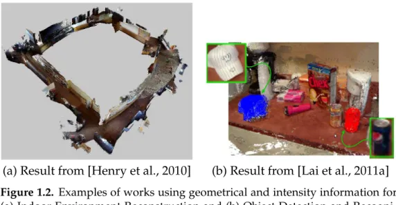
(a) Result from [Henry et al., 2010] (b) Result from [Lai et al., 2011a]
Figure 1.2. Examples of works using geometrical and intensity information for (a) Indoor Environment Reconstruction and (b) Object Detection and Recogni-tion.
allows to use any of detector algorithms proposed every year. The reasons we chose the others properties will be detailed in the next section.
1.1
Motivation
The matching of descriptors is at the core of a myriad of applications in computer vision and robotics. Three-dimensional alignment (Figure 1.2 (a)), SLAM, tracking, detection and recognition of objects (Figure 1.2 (b)) and structure from motion are some of the applications that rely on feature point matching methods. Hence, it is of great importance to the success of these systems to develop robust, invariant and discriminative descriptors, since rotation, illumination and the viewpoint are not fixed. Moreover, the data of these systems is noisy.
Additionally, the requirements from the online application for limited hard-ware, as mobile phones and embedded systems, are not reached at an acceptable level by the state-of-the-art descriptors. This leads to the demand for descriptors that are robust, fast to compute and match, and memory efficient.
1.2. THESIS GOALS AND CONTRIBUTIONS 5
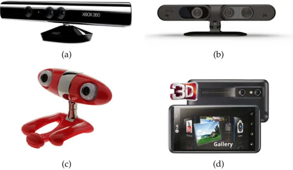
(a) (b)
(c) (d)
Figure 1.3. Examples of recently released domestic tridimensional sensors: (a) Microsoft Kinect; (b) ASUS WAVI Xtion; (c) Minoru Webcam 3D; (d) 3D LG Optimus cell phone.
RGB-D systems output color images and the corresponding pixel depth infor-mation enabling the acquisition of both depth and visual cues in real-time. These systems have opened the way to obtain 3D information with unprecedented trade-off of richness and cost. One such system is the Kinect [Microsoft, 2011], a low cost commercially available system that produces RGB-D data in real-time for gaming applications.
Robust, fast and low memory consumption descriptors that efficiently use the available information, like color and depth, will play a central role in the search of the optimal descriptor.
1.2
Thesis Goals and Contributions
In this thesis, we present three novel descriptors, which efficiently combine inten-sity and shape information to substantially improve discriminative power enabling enhanced and faster matching. We aim to advance in the task of building robust and efficient descriptors suitable for online applications. Experimental results presented later show that our approach is both robust and computationally efficient.
align-ment and object recognition and obtained better results when comparing with three other descriptors well known in literature.
The main contributions of this thesis can be summarized by the three devel-oped RGB-D descriptors:
1. The Enhanced Descriptor for Visual and Depth Data (EDVD), which effi-ciently combines visual and shape information to substantially improve dis-criminative power, enabling high matching performance. Unlike most current methodologies, our approach includes in its design scale and rotation trans-forms in both image and geometrical domains;
2. Binary Appearance and Shape Elements (BASE) that, like EDVD, efficiently fuses visual and shape information to improve the discriminative power, but provides faster matching and lower memory consumption;
3. A fast, lightweight and robust feature point descriptor, called Binary Robust Appearance and Normal Descriptor (BRAND), which presents all the invari-ant properties of EDVD and is as fast as BASE with the same memory con-sumption.
In summary, our main contribution is to exploit the techniques to build a ro-bust, fast and low memory consumption descriptor suitable for online 3D mapping and object recognition applications, which is able to work in modest hardware con-figurations with limited memory and processor use.
Portions of this work have been published in the following international peer reviewed journal, conference proceedings and workshop:
1. Nascimento, E. R.; Oliveira, G. L.; Vieira, A. W.; Campos, M. F. M.. On The
Development of a Robust, Fast and Lightweight Keypoint Descriptor.
Neurocom-puting;
2. Nascimento, E. R; Schwartz W. R; Campos, M. F. M.. EDVD - Enhanced
De-scriptor for Visual and Depth Data. IAPR International Conference on Pattern
Recognition (ICPR), 2012, Tsukuba - Japan;
3. Nascimento, E. R.; Oliveira, G. L.; Campos, M. F. M.; Vieira, A. W. and Schwartz, W. R. BRAND: A Robust Appearance and Depth Descriptor for
RGB-D Images, in IEEE Intl. Proc. on Intelligent Robots and Systems (IROS), 2012,
1.3. ORGANIZATION OF THE THESIS 7
4. Nascimento, E. R.; Schwartz, W. R.; Oliveira, G. L.; Vieira, A. W.; Campos, M. F. M.; Mesquita, D. B.. Appearance and Geometry Fusion for Enhanced Dense 3D
Alignment, in XXV Conference on Graphics, Patterns and Images (SIBGRAPI),
2012, Ouro Preto - Minas Gerais - Brazil;
5. Nascimento, E. R.; Oliveira, G. L.; Vieira, A. W.; Campos, M. F. M.. Improving Object Detection and Recognition for Semantic Mapping with an Extended Intensity
and Shape based Descriptor. In: IROS 2011 workshop - Active Semantic
Perception and Object Search in the Real World (ASPAVS11), 2011, San Francisco -California - USA.
1.3
Organization of the Thesis
Chapter 2
Related Work
In spite of all the adversities in the correspondence of pixels in images, like noise and ambiguity, much progress towards estimating an aproximated correspondence relationfc(defined in Chapter 1) has been made in the last decade for color images and range images.
Methodologies for keypoint detectors, descriptor creation and matching have been proposed in the last decade with great success. In this chapter we review the related literature on the creation of descriptors. Due to the enormous quantity of work that has been published on the subject, we will focus on those with a direct relation with ours.
2.1
Keypoint Detection
As seen in Figure 1.1, the first step in the matching process is keypoint detection. Thus, we present in this section a discussion of the main concepts present in detector algorithms.
The main goal of detectors is to assign a saliency score to each pixel of an image. This score is used to select a small subset of pixels that present as properties [Tuytelaars and Mikolajczyk, 2008]:
• Repeatability: The selected pixels should be stable under several image pertu-bations;
• Distinctiveness: The neighborhood around each keypoint should have intesity pattern with strong variantions;
• Locality: The features should be a function of local information;
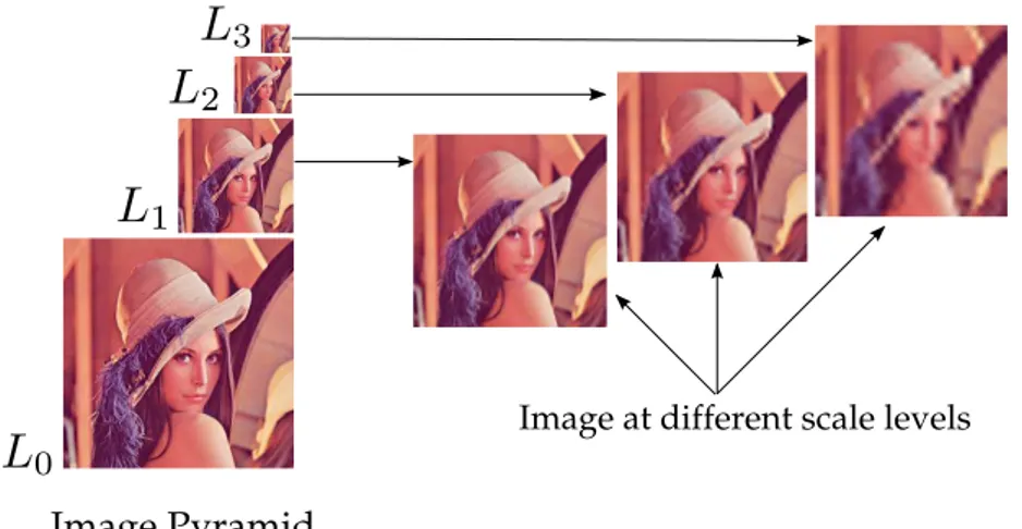
Figure 2.1. The original imageL0is repeatedly subsampled and smoothed
gen-erating a sequence of reduced resolution imagesL1,L2andL3 in different scale
levels.
• Accurately localizable: The localization process should be less error-prone with respect to scale and shape;
• Efficient: Low processing time.
Corner detection was used in earlier techniques to detect keypoints [Zhang et al., 1995; Schmid and Mohr, 1997], however, corner detection approaches have a limited performance since they generally examine the image at only a single scale.
The more recent detector algorithms are designed to detect the same key-points in different scalings of an image. Using the scale-space representation [Linde-berg, 1994], these algorithms are able to provide scale invariance in image features. Futhermore, the scale-space representation is useful in reducing the noise.
The scale-space representationLfor an imageIis defined as
L(x, y, σ) =G(x, y, σ)∗I(x, y), (2.1)
where∗is the 2D convolution operator and
G(x, y, σ) = 1 2πσ2e
x2+y2
2σ2 (2.2)
is a Gaussian kernel.
2.2. DESCRIPTOR EXTRACTION 11
pyramid. In addition to detection, this process determines the scale of each keypoint found.
In order to provide invariance to rotation transformations, detector algorithms estimate the characteristic direction of the region around each keypoint. This direc-tion is called Canonical Orientation, and it is defined by the pattern of gradients in the keypoint’s neighborhood.
2.2
Descriptor Extraction
The approaches for assembling descriptors for keypoints can be categorized based on the type of data acquired from the scene. That is, data may be composed of textured images or of depth images.
In the last years, textured images have been the main choice. They provide a rich source of information which naturally ushered the use of texture based descrip-tors in several methods despite their inherent complexity. Computer Vision litera-ture presents numerous works on using different cues for correspondence based on texture [Lowe., 2004; Bay et al., 2008; Calonder et al., 2010; Leutenegger et al., 2011; Rublee et al., 2011]. Virtually all of these techniques are based on the analysis of the distribution of local gradients.
Scale Invariant Feature Transform (SIFT) and Speeded-Up Robust Features (SURF) are the most popular image descriptors algorithms. Thanks to their descrim-inative power and speed, they became standard for several tasks such as keypoint correspondence and object recognition. For these reasons we chose both as com-petitors with the methods proposed in this thesis and we detail them in the next sections. We also present Binary Robust Independent Elementary Features (BRIEF) descriptor since our methodology was partially inspired on it.
2.2.1
SIFT Descriptor
Lowe, in his landmark paper [Lowe., 2004], presents the keypoint descriptor called SIFT. Although Lowe proposed SIFT to be used in object recognition applications, due to the high discriminative power and stability, his algorithm became the most used keypoint descriptor in a myriad of other tasks.
Figure 2.2. Computing a SIFT descriptor. First, the magnitudes and orienta-tions of local gradients are computed around the keypoint. The magnitudes are weighted by a Gaussian window (blue circle) and accumulated in4orientation histograms. Each histogram has8bins of orientation corresponding to a subre-gion. Then, the bins for all histograms are concatenated to form the descriptor. Unlike the example in this image, the standard implementation of SIFT uses a
16×16sample on the left and4×4histograms on the right. Illustration taken from [Lowe., 2004].
and orientation. The magnitudem(x, y)of the pixel(x, y)is given by:
m(x, y) = p[I(x+ 1, y)−I(x−1, y)]2+ [I(x, y+ 1)−I(x, y−1)]2, (2.3)
and its orientationθ(x, y)is estimated as:
θ(x, y) = arctan
I(x, y+ 1)−I(x, y−1)
I(x+ 1, y)−I(x−1, y)
, (2.4)
whereI(x, y)is the intensity of pixel(x, y)of the smoothed and subsampled image in the level of the scale-space pyramid where the keypoint was detected.
A region of16×16pixels, centred in the keypoint localization, is subdivided in 4×4subregions. These16subregions are rotated relative to the canonical orientation computed for the keypoint. For each subregion, a histogram with8orientation bins is computed. The magnitute values for all gradients inside of the region are weighed by a Gaussian window and accumulated into the orientation histograms.
2.2. DESCRIPTOR EXTRACTION 13
Figure 2.3. Computing a SURF descriptor. Two Haar wavelet filters (left) are used to estimate the local gradients inside of an oriented quadratic grid centred in the keypoint position (middle). The wavelet responses are weighted with a Gaussian (blue circle) and, for each2×2sub-region (right), is computed the sums of dx, |dx|, dyand|dy|relatively to the canonical orientation (red arrow). The final descriptor is composed of4×4 vectorsv = (P
dx,P
dy,P
|dx|,P |dy|)
concatenated. Illustration taken from [Bay et al., 2008].
2.2.2
SURF Descriptor
Although SIFT brings forth discriminative descriptors, it has a high processing cost. To overcome this issue, Bay et al. [2008] propose the faster algorithm SURF. This algorithm can be seen as an approximation of SIFT and shares the idea of using histograms based on local gradients. Despite the approximations in descriptor cre-ation, there is no significant loss in robustness or rotation and scale invariance.
Like SIFT, the creation process of SURF descriptor consists of centering a square region in the keypoint location. The keypoint scale in scale-space is used to determine the size of this region and the canonical orientation of its direction. However, differently from SIFT which uses pixel differences to compute the gra-dients, SURF creates the local gradient distribution using Haar wavelet responses in horizontal and in vertical directions (the Haar wavelet filters used are shown in Figure 2.3).
SURF computes, in both x and y directions, four sums: i) sum of gradients
P
dx; ii) sum of gradientsP
dy; iii) sum of absolute gradientsP
|dx|and iv) sum of absolute gradientsP
|dy|( see 2.3). These sums are computed for each one of the4×
4sub-regions and concatenated forming16vectorsv= (P
dx,P
dy,P
|dx|,P
Figure 2.4. Patch Pwith 48×48 pixels indicating 256sampled pairs of pixel locations used to construct the binary feature.
2.2.3
BRIEF Descriptor
Despite the high discriminative power of SIFT and SURF, they suffer with slow match and high processing time and memory consumption (vectors with128and64 floats respectively). Hence, these algorithms are not feasible in applications where it is necessary to store millions of descriptors or have real-time constraints.
Dimensionality reduction methodologies, such as Principal Component Anal-ysis (PCA) [Ke and Sukthankar, 2004], Linear Discriminant Embedding (LDE) [Hua et al., 2007], algorithms based on L1-norm-based [Pang and Yuan, 2010] and [Pang et al., 2010], and quantization techniques that convert floating-point coordinates into integers coded on fewer bits are used by some of the approaches to solve the de-scriptor dimensionality problem. However, those techniques involve further post-processing, usually with high computation charge, of a long descriptor which is already costly to compute. Furthermore, PCA and LDE methodologies may lead to overfitting and reduce the performance.
More recently, several compact descriptors, such as Calonder et al. [2010], Leutenegger et al. [2011], Rublee et al. [2011], Ambai and Yoshida [2011], Kemb-havi et al. [2011] and Choi et al. [2012] have been proposed employing ideas similar to those used by Local Binary Patterns (LBP) [Ojala et al., 1996]. Those descriptors are computed using simple intensity difference tests, which have small memory consumption and modest processing time in the creation and matching processes.
2.3. GEOMETRICALDESCRIPTOREXTRACTION 15
Assembling binary descriptors In order to generate a string of bits, BRIEF’s ap-proach consists of computing individual bits by comparing the intensities of pairs of points in a neighborhood around each detected keypoint. Similar to SIFT and SURF descriptors, the BRIEF methodology estimates for every keypoint a gradient field.
The pairs are selected by a patchP of sizeS×S, centred at a keypoint posi-tion. This patch is smoothed to reduce sensitivity, increase stability and repeatibility. Calonder et al. [2010] tested five configurations to build a spatial arrangement of the patch and the best results were reached by using an isotropic Gaussian distribution (X,Y) i.i.d. N(0,S2
25). Figure 2.4 illustrates this arrangement. Each pair of pixels
are indicated with line segments. This pairs distribution is created with random function, however, is fixed for all keypoints and it is centred at keypoint’s location.
For all positions in a set of (x,y)-locations, defined by the distribution, the following function is evaluated:
f(P,x,y) =
1 ifp(x)< p(y)
0 otherwise, (2.5)
wherep(x)is the pixel intensity at positionx= (u, v)T in the patchP. The final descriptor is encoded as a binary string computed by:
b(P) =
256
X
i=1
2i−1f(P,x
i,yi). (2.6)
One of the main disadvantages of BRIEF is the lack of invariance to scaling and rotation transform, differently from SIFT and SURF, BRIEF algorithm does not compute the canonical orientation. Nevertheless, according to the authors, BRIEF has shown be invariant to rotation of small degrees. Also, there are cases that the image orientation can be estimated using other sensors, such as a mobile phone equipped with Inertial Measurement Unit (IMU) and a robot that knows its attitude [Calonder et al., 2010].
2.3
Geometrical Descriptor Extraction
With the growing availability of inexpensive, real time depth sensors, depth images are becoming increasingly popular and many new geometrical-based de-scriptors are proposed each year. The methodologies presented by Rusu et al. [2008a], Rusu et al. [2008b], Rusu et al. [2008c], Rusu et al. [2008d], Rusu et al. [2009], Steder et al. [2010], Tombari et al. [2010] and Steder et al. [2011] are some of the most recent approaches.
As in the case of textured images, region matching on geometrical data is most advantageous. However, due to the geometrical nature of the data, effective descrip-tors tend to present higher complexity, and large ambiguous regions may become a hinderance to the correspondence process.
Geometrical descriptors take advantage of the matrix like structures of depth images which have low discriminative power and are less useful. Nevertheless, information of such descriptors is most relevant for textureless scene regions where texture based descriptors are doomed to fail.
In order to define robust descriptors for depth data, large amounts of data are necessary to encompass sufficient information and to avoid ambiguities. Spin-Image [Johnson and Hebert, 1999] is the most popular and used algorithm of such descriptors.
2.3.1
Spin-Image
Johnson proposed in his paper [Johnson and Hebert, 1999] to represent a surface with a set of images enconding global properties. He created a view-independent descriptor, where an object-oriented coordinate system is fixed on the surface and does not change when viewpoint changes.
The object-oriented coordinate system is defined by a three-dimensional point
pand its normal n. It is usually trivial to estimate the direction of the normal for each point on the surface as the vector perpendicular to the surface in that point.
The origin of object-oriented coordinate systems is defined by a keypoint loca-tionp. A tangent plane P to the pointp is oriented perpendicularly to the surface normaln. Using the pointpand its normaln, the algorithm defines the lineL, which together with the planeP determine a cylindrical coordinate systemO without the polar angle coordinate, since it is not possible to determine this coordinate using just the point and its normal surface. Thus, in this cylindrical coordinate system, a pointx is represented using α and β coordinates, where α is the (non-negative) perpendicular distance to lineLandβis the signed perpendicular distance to plane
2.4. FUSING IMAGE ANDGEOMETRICALINFORMATION 17
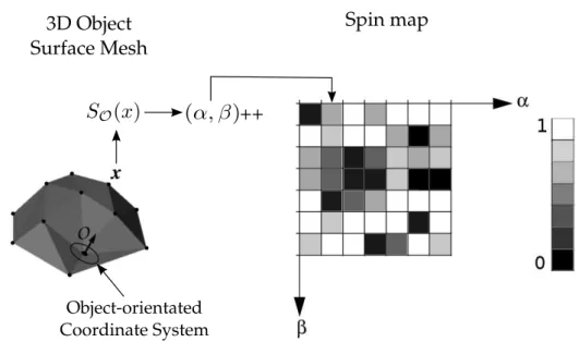
Figure 2.5.Creation of a cylindrical coordinate system based on pointpand the normal surfacenon this point. A pointxcan be represented in this cylindrical
coordinate system using coordinatesα andβ. The planeP defines the object-oriented coordinate system. Illustration taken from [Johnson and Hebert, 1999].
After creation of the coordinate system, the next step is to generate a 2D image called a spin map. First, all point x ∈ R3 in the point cloud are projected onto the
cylindrical coordinate systemO, using the projection functionSO :R3 →R2
SO(x)→(α, β) =pkx−pk2− hn,(x−p)i2,hn,x−pi, (2.7)
whereh.iis the dot product.
Then, the spin map is assembled by an accumulating schema. Using a 2D his-togram with discrete bins to α and β values, the methodology updates these bins according to the projected points in the cylindrical coordinate system. This accumu-laton process is shown in Figure 2.6.
By using a local coordinate system attached to the object surface and oriented along the keypoint normal to build the spin maps, the Spin-Image algorithm pro-vides robustness and invariance to rotation transformation. Since the signature is independent of the viewpoint. It is well suited for depth maps and meshes in gen-eral.
Even though the geometrical descriptors, such as Spin-Image are accurate, they present high computational cost and memory consumption, and constructing a single descriptor for general raw point clouds or range images involves complex geometric operations.
2.4
Fusing Image and Geometrical Information
im-3D Object Surface Mesh
Spin map
Object-orientated Coordinate System
++
Figure 2.6. Spin-Image creation using 2D histogram. After the projection of a pointxin the coordinate systemO, the resulting 2D point is accumulated into a discrete bin. Illustration based on [Johnson and Hebert, 1999].
prove object detection and recognition rate. The fusion of appearance and geometry information, which has shown a very promising approach for object recognition, is still in its opening movements. For example, Lai et al. [2011a,b] and Henry et al. [2010] combine both sources of information, but they applied well-known descrip-tors for each type of data, such as SIFT for texture and Spin-Image for shape and then concatenate both to form a new signature. However, as far as efficacy is con-cerned, Lai et al. [2011b] have shown that the combination of intensity and depth information outperforms approaches using either intensity or depth alone.
Most likely, the main reason many descriptors have not used shape informa-tion can be partially explained by the fact that, until recently, object geometry could not be easily or quickly obtained so as to be combined with image feature data.
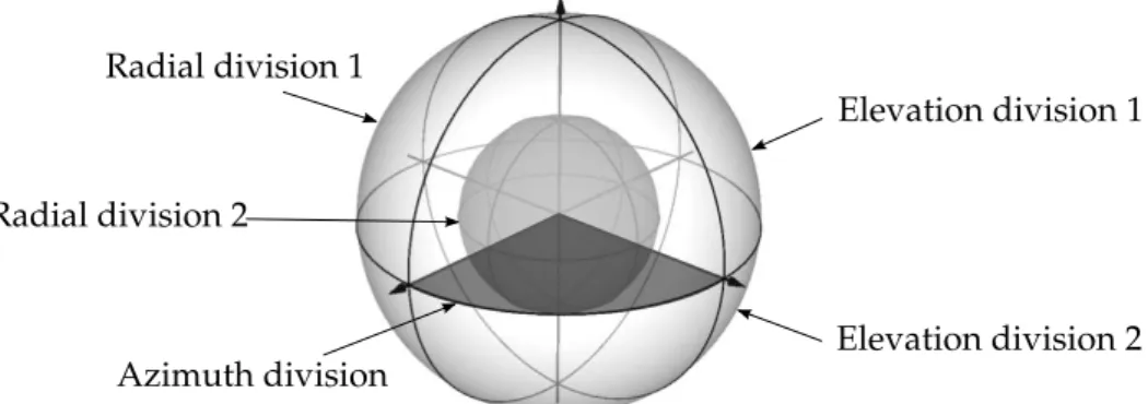
2.4. FUSING IMAGE ANDGEOMETRICALINFORMATION 19
Elevation division 1
Elevation division 2 Azimuth division
Radial division 1
Radial division 2
Figure 2.7. Isotropic Spherical Grid used by CSHOT descriptor. The space is partioned in32sectors:4azimuth divisions (the standard implementation uses
8divisions), 2 elevation divisions and2 radial divisions. Illustration based on [Tombari et al., 2011].
the recognition rate in cluttered scenes with obstruction. Since CSHOT is the state-of-the-art of shape and texture descriptor, we choose it as the main competitor of our methodology and we detail its construction process in next section.
2.4.1
CSHOT Descriptor
CSHOT signatures are composed of two concatenated histograms, one contains the geometric features and other with the texture information enconded. An isotropic spherical grid is overlaid onto each keypoint location. This grid has32sectors that divides the space in8azimuth divisons,2elevation divisions and2radial divisons (Figure 2.7 illustrates this spherical grid with4azimuth divisons).
For each sector, two local histograms are computed, one based on geometrical features and one with texture information. In the former, the algorithm accumulates into histograms bins according to the geometric metric
f(K, P) =hNK, NPi, (2.8) where K is the keypoint, P represents a generic vertex belonging to the spherical support around K, NK and NP are the normals of keypoint and generic vertex, respectively andh.iis the dot product.
The accumulation in the texture histograms is performed using color triplets in CIELab space and the metric is based on theL1 norm, given by
l(RK, RP) =
3
X
i=1
where,RK andRP are the CIELab representation of the RGB triplet of the keypoint
Kand a generic vertexP in spherical support.
The standard implementation of CSHOT uses 11 bins for geometrical his-tograms and31bins for texture histograms. Since 32histograms are computed for each cue, the resulting signature is a1344-length vector.
In this work we take a similar approach to the problem. Our technique builds a descriptor which simultaneously takes into account both sources of information to create a unique representation of a region simultaneously considering texture and shape.
Our method aims at fusing visual (texture) and shape (geometric) information to enrich the discriminative power of our matching process to registration. On one hand, image texture information can usually provide better perception of object fea-tures, on the other hand depth information produced by 3D sensors is less sensitive to lighting conditions. Our descriptor brings forth the advantages of both texture and depth information. Moreover, it uses less memory space, since it was designed as a bit string, and less processing and matching time due to the low cost computa-tions needed.
2.5
Descriptors Rating based on the
Π
Set
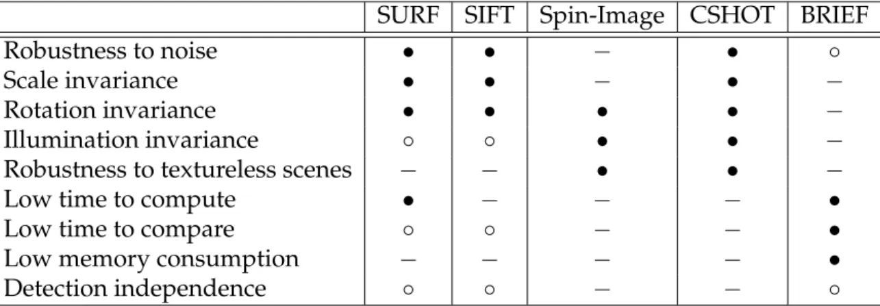
Table 2.1 summarizes the assigned properties of the descriptors described in this section. We give an individual rating with respect to the eight properties ofΠ set. Recall the properties described in Chapter 1, theΠset is composed of eight proper-ties:
1. Robustness to noise;
2. Scale invariance; 3. Rotation invariance;
4. Illumination invariance;
5. Robustness to textureless scenes; 6. Low processing time to compute;
2.5. DESCRIPTORS RATING BASED ON THEΠSET 21
SURF SIFT Spin-Image CSHOT BRIEF
Robustness to noise • • − • ◦
Scale invariance • • − • −
Rotation invariance • • • • −
Illumination invariance ◦ ◦ • • −
Robustness to textureless scenes − − • • −
Low time to compute • − − − •
Low time to compare ◦ ◦ − − •
Low memory consumption − − − − •
Detection independence ◦ ◦ − − ◦
Table 2.1.Descriptors rating based on the properties of an robust descriptor.
9. Keypoint detection independence.
We rate each descriptor of this chapter using the following criteria:
− : Descriptor does not have implemented any algorithm to cover the property;
◦ : The property is implemented using an approximation;
• : Descriptor has a robust implementation of the property.
Chapter 3
A Computational Approach to
Creation of Keypoint Descriptors
A
S OBSERVED IN THE PRECEDING CHAPTER, on the one hand, the use of texture information results in highly discrimative descriptors, on the other hand, bi-nary strings and depth information from range images can reduce the cost of the descriptor creation and matching steps and provide descriptors robust to lack of texture and illumination changes.Unlike tradional descriptors, such as SIFT, SURF and Spin-Image, that use only texture or geometry information, this chapter presents three novel descriptors to en-code visual and shape information. However, differently from the work of Tombari et al. [Tombari et al., 2011], our algorithms provide robust, fast and lightweight signatures for keypoints. The methodology used by our descriptors uses the best information of both worlds in an efficient and low cost way.
All algorithms presented in this thesis receive as inputs a data pair (I, D), which denotes the output of a RGB-D sensor and a listKof detected keypoints. For each pixel x, I(x)provides the intensity andD(x)the depth information. Further-more, we estimated a normal surface for allxas a mapN, whereN(x)is efficiently estimated by Principal Component Analysis (PCA) over the surface defined by the depth map.
3.1
General Methodology
In this section we detail the methodology used to design three new descriptors. The stages of this methodology are illustrated in Figure 3.1.
Our methodology is composed of three main steps. In the first step, we
RGB-D Image Keypoint Pattern Analysis Appearance and Geometry Fusion Descriptor Canonical Orientation Scale Estimation s s θ
Figure 3.1. Methodology diagram. After computing the scale factor s using depth information from an RGB-D image, our methodology extracts a patch of the image in the RGB domain to estimate the canonical orientationθof the key-point. Finally, appearance and geometric information are fused together based on the features selected with a pattern analysis.
pute the scale factor using the depth information from RGB-D image. The scale fac-tor is used in the next step (canonical orientation estimation) and in feature analysis in the keypoint’s vicinity. In the canonical orientation estimating step, a patch in the RGB domain is extracted and used to estimate the characteristic angular direction of the keypoint’s neighborhood. At last, we combine both appearance and geometric information to create keypoint descriptors that are robust, fast and lightweight.
3.1.1
Scale Assignment
Due to the lack of depth information in the images, approaches such as Lowe. [2004], Bay et al. [2008] and Leutenegger et al. [2011] use scale-space representation to local-ize keypoints at different scales. The image is represented by a multilevel, multiscale pyramid in which for each level the image is smoothed and sub-sampled.
Since RGB-D images are composed of color as well as depth information, in-stead of computing a pyramid and representing the keypoints in scale-space, we use the depth information of each keypoint to define the scale factorsof the patch to be used in the neighborhood analysis. In this way, patches associated with keypoints farther away from the camera will present smaller sizes.
The scale factorsis computed by the function:
s= max
0.2,3.8−0.4 max(dmin, d)
3
, (3.1)
3.1. GENERAL METHODOLOGY 25
3.1.2
Canonical Orientation Estimation
There are several algorithms to determine the canonical orientation of a keypoint. We tested three methods to be used in our descriptors: Intensity Centroid (IC), SURF-like (HAAR) and SIFT-like (BIN). Our choice was based on the stability and simplicity of the techniques, since they are robust and have small processing time.
Intensity Centroid (IC) The canonical orientation of a keypoint K can be esti-mated by a fast and simple method using geometric moments. The idea behind this is to build a vector from the keypoint’s localization to the centroid patch defined by the moments in the region around the keypoint.
Rosin [1999] defines the moments of a patch of a imageI as:
mpq =
X
x,y
xpyqI(x, y). (3.2)
Similar to Rublee et al. [2011], we compute the momentsm using only pixels (x, y)remaining within a circular region of radius equal to the patch size.
The patch centroidCis determined by:
C =
m10
m00
,m01 m00
, (3.3)
and the canonical orientationθis given by the angle of the vectorKC~ :
θ = atan2(m01, m10), (3.4)
where atan2 is a implementation of the quadrant-aware version of the arctangent function.
SURF-like (HAAR) This algorithm identifies the direction of keypoints using a process more robust to noise based on Haar wavelets responses and a sliding ori-entation window. In order to estimate the canonical oriori-entationθ, a circular neigh-bourhood of radius 6s, wheres is the scale at which the keypoint was detected, is centered around each keypoint.
Figure 3.2. Computing SURF canonical orientation θ. In a circular neighbour-hood of radius6s, two Haar wavelets filters with size4sare used to compute the responses inxandydirection (left image). The responses are plotted in a graph (blue points) and summed. The largest vector (red vector) defines the canonical orientation (right image).
the keypoint’s orientation. The responses in the xand y axes are added, yielding an orientation vector within the window. The canonical orientation is chosen as the vector with the largest magnitude. Figure 3.2 depicts this procedure.
SIFT-like (BIN) The third method is similar to the one used in the SIFT algorithm. A histogram with36directions is formed by taking values within a region around the keypoint’s location. An accumulation is performed adding the values ofm(x, y) computed using Equation 2.3 and weighted by a Gaussian function around the key-point. The orientation of each pixelθ(x, y)is computed by Equation 2.4. The highest peak of the histogram determines the canonical orientation of the local gradients. However, differently from SIFT’s algorithm which includes more keypoints when there are other peaks within80%of the highest, we pick only a single orientation.
3.1.3
Appearance and Geometry Fusion
The importance of combining shape and visual information comes from the possi-bility of creating descriptors robust to textureless objects, lack of illumination and scenes with ambiguous geometry.
3.2. EDVD DESCRIPTOR 27
Finally, we combine the result of this analysis in a unique vector which represents the signature of the keypoint.
In the next sections we will detail these steps and assemble three novel descrip-tors using our methodology as a design guide. The texture analysis step is shared by all the descriptors, therefore we will present it as follows.
Appearance Analysis The gradient directions are computed using simple inten-sity difference tests, which have small memory consumption and modest process-ing time. Given an image keypointk ∈ K, assume a circular image patchPof size
W ×W (in this work we consider9≤W ≤48) centered atk. We use a fixed pattern with locations given by distribution functionD(k)for sampling pixel pairs around the keypoint k. We also smooth the patch with a Gaussian kernel withσ = 2and a window with 9×9pixels to decrease the sensitivity to noise and increase stability in the pixel comparisons.
Let the fixed set of sampled pairs from P be S = {(xi,yi), i = 1, . . . ,256}. Before constructing the visual feature descriptor, the patch P is translated to the origin and then rotated and scaled by the transformationTθ,s, which produces a set P, where
P ={(Tθ,s(xi),Tθ,s(yi))|(xi,yi)∈S}. (3.5) This transformation normalizes the patch to allow comparisons between patches. Then, for each pair(xi,yi)∈P, we evaluate
τa(xi,yi) =
1 ifpi(xi)< pi(yi)
0 otherwise, (3.6)
where the comparison term captures gradient changes in the keypoint neighbor-hood.
3.2
EDVD Descriptor
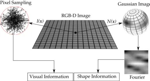
In this section, we present our descriptor called Enhanced Descriptor for Visual and Depth Data (EDVD). After extracting the gradient features according to our method-ology, we group the results of eight tests and represent it as a floating point number. Therefore, we can use a vector Va with 32 elements to store the results of all 256 comparisons performed by the functionτa(Equation 3.6).
appli-Shape Information Visual Information
Extended Gaussian Image
Fourier RGB-D Image
Pixel Sampling
I(x) N(x)
Figure 3.3. The proposed descriptor combines shape and visual information based on invariant measurement in both domains.
cation of the Fourier transform. This process is illustrated in Figure 3.3.
Geometrical Feature Analysis We use orientation histograms to capture the geo-metric characteristics of the patchPin the 3D domain. Since orientation histograms are approximations of Extended Gaussian Images (EGI) [Horn, 1984], they consti-tute a powerful representation invariant to translational shift transformations.
The first step in orientation histograms creation is to represent each normal
pn(x)in spherical coordinates(φ, ω)(Figure 3.4). These angles are compute as [Het-zel et al., 2001]:
φ= arctan
nz
ny
, ω = arctan
p n2
y+n2z
nx
!
. (3.7)
3.3. BRAND DESCRIPTOR 29
Then, the coordinatesφandωare discretized into8values each, and the num-ber of normals falling inside each discretized orientation is accumulated. Figure 3.3 depicts the accumulation of normal directions in the sphere. Dark spots represent a large number of normals accumulated in that orientation.
Since rotations in the normal orientations become translations in the EGI do-main, we apply the Fourier transform in the EGI domain to obtain a translation invariant Fourier spectrum. Finally, the Fourier spectrum is linearized and con-verted to a64-dimension vectorVs. In addition to the rotation invariance, the use of spectral information emphasizes differences among different descriptors.
Fusion Process Once the visual and geometrical features have been extracted, we concatenate the geometrical vectorVgand the appearance vectorVa, creating a 96-dimension vector which captures both appearance and geometrical information. Despite the high quality of matching and invariance to rotation transforms, EDVD algorithm has drawbacks in the processing time to create the EGI histograms and the vector size. Furthermore, the EDVD vectors are compared using correlation function, which is slower than other approaches such as Hamming distance.
3.3
BRAND Descriptor
In the following paragraphs we detail the design of our second descriptor, which we call BRAND from Binary Robust Appearance and Normal Descriptor. Throughout this section are shown the descriptor’s characteristics and how they cover all the properties inΠset as well as how it overcomes the EDVD deficiencies.
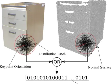
Geometrical Feature Analysis and Fusion Information There are several choices available to compose a descriptor, and bit strings are among the best ap-proaches, mainly due to the reduction in dimensionality and efficiency in compu-tation achieved with their use. One of the greatest advantages of using a binary string as descriptors, besides its simplicity, is its low computational cost and mem-ory consumption, whereas each descriptor comparison can be performed using a small number of instruction on modern processors. For instance, modern architec-tures have only one instruction (POPCNT) to count the number of bit sets in a bit vector [Intel, 2007].
Figure 3.5. Binary descriptor diagram. The patch of sizeS ×S is centered at the location of keypoint. For all positions in a set of (x,y)-locations the intensity changes in image and the displacement of normals inside of projected patch in the point cloud is evaluated.
et al., 2011; Ambai and Yoshida, 2011], we embed geometric cues into our descriptor to increase robustness to changes in illumination and the lack of texture in scenes.
Following the steps in our methodology, unlike EDVD that builds an EGI his-togram and uses concatenation operator to form the final vector, BRAND evaluates the function 3.8 for each pair(xi,yi)∈P:
f(xi,yi) =
1 ifτa(xi,yi)∨τg(xi,yi)
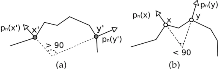
0 otherwise, (3.8)
where the functionτa(.)(Equation 3.6) captures the characteristic gradient changes in the keypoint neighborhood andτg(.)function evaluates the geometric pattern on its surface. Figure 3.5 illustrates the construction process of the bit string.
3.3. BRAND DESCRIPTOR 31
test is accomplished by the local curvature signal,κ, estimated as:
κ(xi,yi) = hps(xi)−ps(yi), pn(xi)−pn(yi)i, (3.9)
where h.iis the dot product andps(x)is the3Dspatial point associated to the pixel
xand the depth D(x). Figure 3.7 illustrates an example where the dot product be-tween surface normals is ambiguous, sinceθ1 =θ2, but different signed curvatures,
κ1 < 0and κ2 > 0, are used to unambiguously characterize these different shapes,
besides capturing convexity as additional geometric features. The final geometric test is given by:
τg(xi,yi) = (hpn(xi), pn(yi)i< ρ)∧(κ(xi,yi)<0). (3.10)
Finally, the descriptor extracted from a patchpassociated with a keypointkis
y' x'
pn(y') pn(x')
> 90
x
pn(y)
pn(x)
< 90 y
(a) (b)
Figure 3.6. Image (a) shows a surface where the normal displacement of points
x′andy′ is greater than90degrees leading to bit value1. In image (b) is shown the normals of pointsxandythat lead to bit0due to displacement less than90
degrees.
pn(x) pn(y) pn(z)
κ1 < 0
θ2
θ1 κ2 > 0
ps(x) ps(y) ps(z)
Keypoint RGB-D Image
Appearance and Geometry
Fusion
Binary Descriptor Pattern Analysis
Figure 3.8.BASE diagram. The appearance and geometric information are fused based on the features selected with a pattern analysis.
encoded as a binary string computed by:
b(k) =
256
X
1
2i−1f(x
i,yi). (3.11)
Once the descriptorsb(k1)andb(k2)have been estimated for two keypointsk1
andk2, they are compared using the Hamming distance as
h(b(k1), b(k2)) = 256
X
1
2−(i−1)(b(k1)⊕b(k2))∧1. (3.12)
3.4
BASE descriptor
Not all applications require scale and rotation invariance. For these applications our BRAND descriptor can turn off the invariance properties removing the orientation and scale transformation estimation phases. The new simplified descriptor, called Binary Appearance and Shape Elements (BASE), uses a circular patch with a fix ra-dius of size24to select pairs of pixels and normals in the point cloud. In constrast to BRAND and EDVD, BASE does not compute the canonical orientation. Figure 3.8 shows the BASE diagram. Similar to BRAND, the gradient information and geo-metrical features (based on the normal displacements) are combined using function 3.8.
3.5. INVARIANT MEASUREMENTS OFBRAND ANDBASE 33
3.5
Invariant Measurements of BRAND and BASE
An important characteristic of the approach that we adopted to use geometry from RGB-D images is the relation between normal’s displacement and the transforma-tions of rotation, scale and translation.
To prove the invariace properties of our approach we will present some impor-tant definitions of invariance measurements in geometry [Andrade and Lewiner, 2011].
LetSbe a geometric object andAa transformation.
Definition 3.1 (Invariant Measurement). A geometric measurement is invariant if
∀S,∀A, m(A(S)) =m(S), e.g surface curvature.
Definition 3.2 (Covariant Measurement). A geometric measurement is covariant if
∀S,∀A, m(A(S)) =A(m(S)), e.g tangent vector.
Definition 3.3(Contravariant Measurement). A geometric measurement is
contravari-ant if∀S,∀A, m(A(S)) =A−1(m(S)), e.g normal vector.
Lemma 3.1. Orthogonal transformations preserve the dot product.
Proof. LetAbe an orthogonal transformation andx,y∈Rn:
hAx, Ayi = (Ax)T(Ay) = (xTAT)(Ay) = xT(ATA)y = xTIy=xTy.
Lemma 3.2. The length of vector is preserved under orthogonal transformations.
Proof. LetAbe an orthogonal transformation andx∈Rn:
kAxk2 = (Ax)(Ax)
= xTATAx = xTIx
Lemma 3.3. The angle between two vectors is preserved under orthogonal transformations.
Proof. Let α be the angle between vectorsx and y and let β be angle between the
transformed vectors,AxandAy. According to Lemma 3.1,hAx, Ayi=hx,yi, thus:
kAxkkAykcos(β) =kxkkykcos(α).
Also, according to Lemma 3.2,kAxk=kxkandkAyk=kyk, consequentlycos(β) = cos(α). LetV be a plane spanned by xandy, and let φbe the angle of rotation for vector thex inV plane. For all φ, since cos(β) = cos(α), cos(β +φ) = cos(α+φ). Differenting with respect toφ, we obtain:
−sin(β+φ) =−sin(α+φ),
forφ= 0,sin(β) = sin(α), which impliesβ =α.
Theorem 3.1. The BRAND and BASE measurementmbis invariant under rigid
transfor-mations in the depth space.
Proof. The group of transformations considered is composed of rotation, translation
and uniform scaling. We will show that BRAND and BASE measurement is invari-ant to all these rigid transformations.
• Rotation: Let mb be the geometric measurement used in BRAND descriptor and A is a rotation matrix. We will show that mb(x,y) = mb(Ax, Ay), where
x,y ∈ R3. mb(x,y) = hx,yi and according to Lemma 3.1, orthogonal matrix
preserves the dot product, as every rotation matrix is orthogonal,hAx, Ayi =
hx,yi.
• Translation: Letxbe a normal vector of surfaceS. Letp, q ∈Stwo points that define the normalx,x=p−q. Applying a translationAto the surfaceSusing a vectort,pandqcan be rewrite as:
p′ = p+t
3.6. RATING EDVD, BRAND ANDBASEBASED ON THEΠSET 35
the normalx, after applyingAisx=p′−q′,
x′ = p+t−(q+t)
= p+t−q−t
= p−q
= x.
• Scale: Finally, to provide invariance in scale transformations, all normals used by BRAND are normalized. Indeed, ifAis a uniform scale transform,A(x) =
sx, therefore
sx
||sx|| =
sx s∗1 =x.
Theorem 3.1 shows that our approach provides a way to extract features from an object’s geometry that do not suffer interference from rotation, scale and transla-tion transformatransla-tions.
3.6
Rating EDVD, BRAND and BASE based on the
Π
set
Table 3.1 shows the classification of EDVD, BRAND and BASE descriptor according to the properties fromΠset. Note that all the properties are covered by BRAND and BASE presents a clear improvement on the BRIEF approach for textureless scenar-ios. In the independence detection property, the descriptors were rated according to results presented in Chapter 4.
SURF SIFT Spin-Image CSHOT EDVD BRAND BASE
Robustness to noise • • − • • • •
Scale invariance • • − • • • −
Rotation invariance • • • • • • −
Illumination invariance ◦ ◦ • • • • •
Texture independence − − • • • • •
Low time to compute • − − − ◦ • •
Low time to compare ◦ ◦ − − − • •
Low memory consumption − − − − − • •
Detection independence ◦ ◦ − − ◦ • •
Chapter 4
Experiments
I
N THIS CHAPTER WE DESCRIBE A SET OF EXPERIMENTSto analyze the behavior of our descriptors for matching tasks. Comparisons are performed with the stan-dard approaches of the two-dimensional images descriptors, SIFT [Lowe., 2004] and SURF [Bay et al., 2008], with the geometric descriptor, spin-images [Johnson and Hebert, 1999], and with CSHOT [Tombari et al., 2011], the state-of-the-art approach in fusing both texture and shape information.For the experiments we use the dataset presented in [Sturm et al., 2011]. This dataset is publicly available1 and contains several real world sequences of RGB-D data captured with a KinectTM. Images were acquired at a frame rate of30Hz and a resolution of 640×480 pixels. Each sequence in the dataset provides the ground truth for the camera pose estimated by a motion capture system. We selected four sequences in the dataset to use in our experiments:
• freiburg2_xyz: Kinect sequentially moved along the x/y/z axes;
• freiburg2_rpy: Kinect sequentially rotated around the three axes (roll, pitch and
yaw rotations);
• freiburg2_desk: A handheld SLAM sequence with Kinect;
• freiburg2_pioneer_slam2: A SLAM sequence with a Kinect mounted on the top
of a Pioneer mobile robot.
Figure 4.1 shows a frame sample from each sequence.
1https://cvpr.in.tum.de/data/datasets/rgbd-dataset
(a) (b)
(c) (d)
Figure 4.1. Frame samples from (a) freiburg2_xyz, (b) freiburg2_rpy, (c)
freiburg2_deskand (d)freiburg2_pioneer_slam2.
To evaluate the performance of our descriptors and to compare with other ap-proaches, we applied the same criterion used by Ke and Sukthankar [2004] and Mikolajczyk and Schmid [2005].
Using a brute force algorithm, we matched all pairs of keypoints from two dif-ferent images. If the Euclidean (for SURF and SIFT), Correlation (for Spin-image and EDVD), Cosine (for CSHOT) or Hamming (for BRAND and BASE) distance computed between descriptors dropped below a threshold t, the pair was consid-ered as avalid match. The number of valid matches which have two keypoints cor-respond to the same physical location (as determined by ground truth) defines the
true positivesmatches. On the other hand, if the keypoints in avalid matchcome from
different physical locations, then we increment the number offalse positives. From these values, we compute therecalland1−precision.
Therecallvalues were determined by:
recall = #truepositive