Journal of Engineering Science and Technology Review 8 (3) (2015) 196 -200
Research Article
Analysis of the Effect of Explosion on Altering the Tensions and Strains in Buried
Water Pipes
Ebrahim Alamatian1 and Hamidreza Zahabi2
1.Assistant Professor, Civil Engineering Faculty, Khavaran University of Mashhad 2. Civil Engineering Major, Khavaran University of Mashhad
Received 18 May 2015; Accepted 19 September 2015
____________________________________________________________________________________________ Abstract
Pipelines that are buried in ground are used for transference of water and energy sources. These lines are considered infrastructures and have a high importance. In this paper behavior of soil and pipes are simulated using the finite-element based software ABAQUS, and effect of blast wave on the amount of tension and displacement of a pipe is investigated. The simulations are run for the pipe’s substance, burial depth, dimension, and also the intensity and situation of the explosion. AUTODYN software is used for evaluation of blast wave’s power. Simulation results show the positive effect of increasing the pipe’s dimension and burial depth on reducing the destruction caused by explosion.
Key Words: Buried Pipe, Explosion, Burial Depth, Abaqus
____________________________________________________________________________________________
1. Introduction
Drinking water is one of the necessities of urban life. Normally this water is transferred and distributed using pipe lines. Different variations of pipes produced in Iran and abroad are used for construction of water transference lines and distribution systems. All these pipes are buried to protect them from environmental factors and sabotage. On the other hand, their burial subjects them to other loads like loads due to the soil’s weight, traffic load, or seismic load besides the fluid’s pressure load.
Various factors like the soil characteristics, intensity of ground vibrations, pipe’s internal pressure, pipe’s dimension including its diameter and the thickness of its wall, and the properties of the pipe’s materials contribute to the effect of external forces on the buried pipe, [1]. Normally, it’s said that underground structures are less prone to damage inflicted by earthquakes than surface structures. But in recent earthquakes, lots of these structures have been damaged, [2]. Pipe lines are no exception in this matter. Destruction or taking damage in buried pipes in the event of an earthquake can affect civil facilities substantially and cause a fire to spread, increase financial losses and stop facility networks from giving proper service. Therefore, investigation and analysis of seismic behavior of buried pipe lines has attracted the attention of many researchers, [3]. Many of the previous studies have focused on numerical modeling of buried pipe lines, and have investigated the mutual effect of soil and pipe structure and the tension due to earthquakes. Analysis of the seismic response of buried pipe lines is very complicated and the three dimensional dynamic analysis of the interaction between the soil and the
pipe must be taken into account, [4]. The finite element method (FEM) is convenient for accurate analysis of the seismic response of buried pipe lines. Tohidy et al. using the ANSYS software,studied buried pipes’ behavior in regard to two dimensional displacement of a fault and methods of strengthening them utilizing FRP, [5]. Haghighy and Agha Kuchak analyzed marine pipe lines subjected to loadings due to seismic waves’ propagation and fault displacement, [6]. They investigated the effects of earthquake’s aftermaths including the displacement of various strike slip, normal, reverse, reverse oblique slip, and normal oblique slip faults and also the effect of propagation of the waves issued from the earthquake on inbound pipe lines that are set on the bed surface in both operational and nonoperational states, and studied pipe line’s efficiency according to the operationality criterion in critical conditions.
Leon and Wangconcluded from their field studies that longitudinal and lateral displacements of a buried pipe much dependent on the movement of its surrounding soil, [7]. Usually the buried pipe’s response to the inertia caused by the buried pipe’s displacement is considered inconsiderable and improbable. Leo and Wang’s studies showed that longitudinal and lateral displacements of the buried pipe is much like the movement of the soil and verified subjection of the pipe to seismic loading due to the faults displacement.
Hyuk analyzed a short buried pipeline (between two solid tanks) and studied the effects of seismic force on it using the finite element based software ABAQUS, [8]. He verified using the ABAQUS software for modeling buried pipes. The ToosaabEngineering Consultants firm also simulated the pipe line connecting Toroq Dam to the water and electricity reservoir one dimensionally using the two software, ERAUL 2007 and ABAQUS and utilizing the hybrid model of shell-beam as a case study for a study aiming at strengthening water supply networks of Mashhad,
J
estr
Engineering Science and JOURNAL OFTechnology Review
www.jestr.org
______________
* E-mail address:[email protected]
Iran, [9]. In this study effects of seismic force was simulated by exerting displacement to the fault.
In the current study a buried pipe line is simulated three dimensionally using the finite element based software ABAQUS, and effect of various parameters on distribution of tension in it are investigated. Specifications of the pipes in the simulation are similar to the commercial pipes used in Mashhad’s Water and Wastewater Company.
2. Modeling
The finite element based software ABAQUS is used for numerical modeling of soil and the buried pipe. Three assumptions have been made for modeling. Firstly, the pipe is continuous. In other words the junctions in various points of the line are not taken into consideration. Secondly, the soil is considered homogenous and Coulomb-Mohr theory is applicable. The third assumption is that the soil and the pipe are completely contiguous, in a way that no empty space exists between them. Jeremy’s studies have shown that a vast number of parameters including the soils constitution and substance, mechanical properties of the pipe, etc. affect the water transference pipes’ response to blast waves, [1]. Each of these variantshave a different effect on pipe’s response to the blast wave. It’s not possible to study their simultaneous effect on the pipe’s response, because each of these variants have a different effect in different conditions. In other words when studying the effect of each of these parameters, it is necessary to assume all the other variants constant and reasonable.
In the matter of explosion, estimation of blast force is doneanalytically or using various numerical software. In the present study, SPH numerical method that’s a relatively new method of dynamic analysis of contiguous materials is used together with the AUTODYN software. As for selecting the value of blast force and its situation, we know that different munitions have different blast powers. Normally these munitions’ powers are described by the amount of TNT used in them. As for the available munitions and researching their power in various rockets, etc. finally 3 blast powers were considered for this paper as follows:
• A blast equal to 10 kilograms of TNT on ground surface (the minimum blast power of small rockets).
• A blast equal to 10 kilograms of TNT, 3 meters from the ground surface (rockets with proximity fuses).
• A blast equal to 150 grams of TNT on ground surface (the minimum used in hand grenades).
As for modeling the soil, a cube with dimensions of H=9m, W=10m, and L=30m is considered, [11]. A steel pipe is positioned at the center of this cube. For creation of the pipe in the simulation, shell modeling is utilized and for modeling the contingence between the soil and the pipe, ‘tie’ constraint is used. Details of the process of simulation are available in another paper by the writers, [12].
For studying the contingence between the soil and the pipe and modeling the pipe line, properties of the materials must be specified. In regard to this paper’s goals, and as this study is done for the city of Mashhad, mechanical characteristics of the soil in this region are taken in accordance to the study undertaken by Toosab Engineering
vulnerability of water transference lines and strengthening Mashhad’s water networks against earthquakes, as can be seen in table 1, [9].
Fig. 1. Schematic view of the model
As for resistance characteristics of the pipes, the values can be seen in table 2 in accordance with the manufacturer firms’ standards:
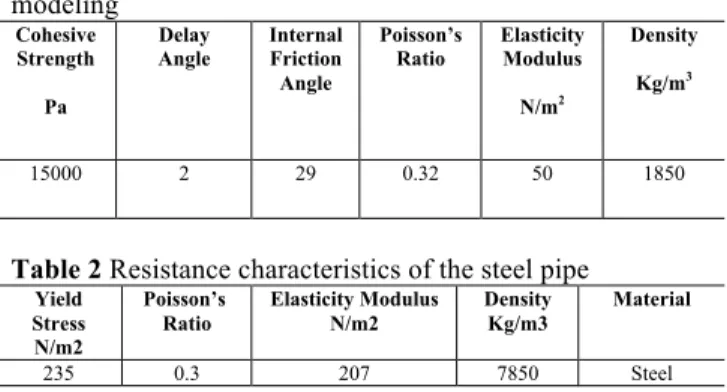
Table 1 Mechanical characteristics of the soil in numerical modeling
Density Kg/m3
Elasticity Modulus N/m2
Poisson’s Ratio Internal Friction Angle Delay
Angle Cohesive
Strength Pa
1850 50
0.32 29
2 15000
Table 2 Resistance characteristics of the steel pipe
Material Density
Kg/m3 Elasticity Modulus
N/m2 Poisson’s
Ratio Yield
Stress N/m2
Steel 7850
207 0.3
235
3. Loading and boundary conditions
3. 1Cell Analysis
In numerical modeling, meshing analysis of the solution space must be done. Meshing must be in a way that gives the results independent of the number of cells. Generally as the computational cells increase, the precision of results also increases and on the other hand the cost of computations will increase substantially (especially in 3D modeling). To determine the optimum number of computational cells a trial and error approach is employed. In this study after several numerical efforts, finally the confirmed meshing has 14637 nodes and 12400 computational cells which include 400 S4R linear cells and C3D8R cells.
4. Numerical Results
4.1. A blast equal to 10 kilograms of TNT on ground surface
In this case, the pressure caused by an explosion equal to 10 kilograms of TNT on the surface of the ground is modeled. According to the data derived from the performed analysis, modeling is done for the strongest pipe material (steel). Thus the force caused by the blast (in addition to the internal force of the pipe and weight of the soil) is exerted on the pipe in a depth of 4 and 6 meters and the model is created.
4.1.1. Steel Pipe with a diameter of 300 mm and burial depth of 4 meters
In figure 2, the graph shows the strain in a steel pipe that has a diameter of 300 mm and is buried in a depth of 4 meters. In this figure the Von Mises tension distribution is shown using different colors. It can be seen that the maximum tension produced in the pipe is 370 MPawhich is more than the yield strength of steel (235 MPa). It is also seen that this maximum tension is produced in a large span of the blast region. Therefore it can be said that in this case, the pipe undergoes plastic deformation and loses its serviceability.
Fig. 2Graph of the strain in the steel pipewith a diameter of 300 mm and burial depth of 4 m
4.1.2. Steel pipe with a diameter of 1500 mm and burial depth of 4 m
In figure 3, the graph shows the strain of the steel pipe with a diameter of 1500 mm and burial depth of 4 meters. The Von Mises tension distribution is also shown in this figure using different colors. It can be seen that the maximum tension produced in the pipe is 365 MPa which is substantially more that the yield strength of steel (235 MPa). Comparison between figures 2 and 3 shows that in this case a smaller span of the pipe is subjected to the maximum tension of 365 MPa. Therefore it can be said that by increasing the pipe’s diameter from 300 to 1500 mm, the
tension value decreases. Still in this case too, the pipe undergoes plastic deformation and loses its serviceability.
Fig. 3 Graph of the strain in the steel pipe with a diameter of 1500 mm and burial depth of 4 m
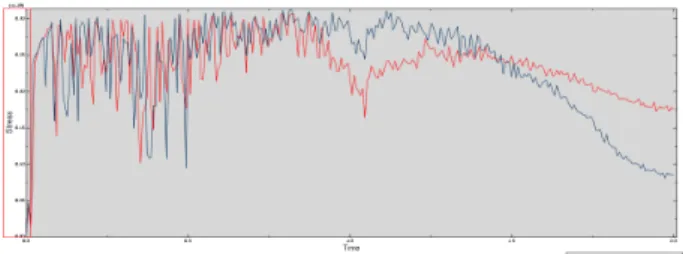
To better investigate the results, in the graph in figure 4 variations in the Von Mises tension in different times are shown for a point in the middle of the pipe and directly under the explosion point. It is observed that the maximum tension is more than the yield strength of steel (235 MPa).
Fig. 4 Graph of the strain in the steel pipe with a diameter of 1500 mm and burial depth of 4 m
4.1.3. Steel pipe with a diameter of 1500 mm and burial depth of 6 meters
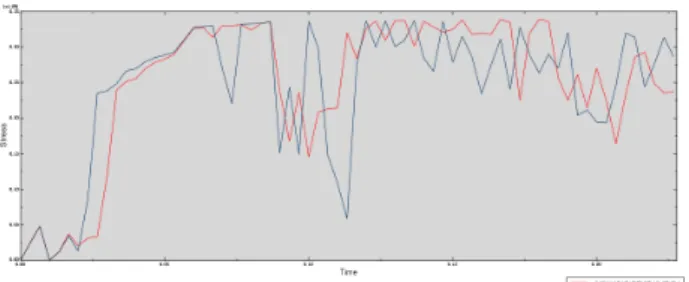
According to the observations of section 4.1.1 and the conclusion that states that as the pipe’s diameter increases, the value of tension decreases; in this section a pipe with a diameter of 1500 mm in a burial depth of 6 meters is modeled. In figure 5 the strain in the pipe is shown as well as Von Mises tension distribution. Also in figure 6 graph of variations in the Von Mises tension in a point on the pipe which is directly under the explosion location is shown in different times. It is observed that in this case too, the maximum tension in the pipe (356 MPa) is more than the yield strength of steel and therefore the pipe deforms.
Fig. 6 Graph of the strain in the steel pipe with a diameter of 1500 mm and burial depth of 6 m
According to the modeling in this section it can be said that under all conditions, all the studied pipes in this paper undergo deformation and are demolished when subjected to an explosion equal to 10 kilograms of TNT on the ground surface.
4.2 A blast equal to 10 kilograms of TNT at a distance of 3 meters from ground surface
In this case too, like the previous section,pressure is assumed to be the force caused by a blast of 10 kilograms of TNT. But the explosion takes place 3 meters from the ground surface so the blast force that reaches the ground surface is reduced. Modeling done by AUTODYN software shows that in this case the maximum pressure exerted on the ground surface is approximately 100 bars. Previous studies have shown that among the pipes considered in this study, the polyethylene pipe is the weakest, [14]. Therefore in this section results of this type of pipe that is buried 2 m under the ground surface (the most critical case) will be presented.
In figure 7 graph of the strain of the polyethylene pipe buried in a depth of 2 meters is shown along with variations in the Von Mises tension in the pipe (using colors). In figure 8 variations in the Von Mises tension in a point on the pipe which is directly under the explosion point is shown for different times. It is observed that in this case the maximum tension is 7.9 MPa which is less than the yield strength of the polyethylene pipe (approximately 30 MPa). Therefore in this case the pipe is not demolished and can very well withstand the blast wave. Thus it can be concluded that if the explosion happens at a distance of 3 meters from the ground surface, none of the pipes in this study will take damage.
Fig. 7 Graph of the strain in the polyethylene pipe with a burial depth of 2 m
Fig. 8Graph of the strain in the polyethylene pipe with a burial depth of 2 m
4.3. Explosion of a hand grenade on the ground surface As saboteurs can use hand grenades, in this section the effect of these grenades’ explosion on the buried pipe is investigated. Usually hand grenades have 150 grams of explosives. Our model showed that if a grenade explodes on the ground surface it will produce a maximum pressure of 200 bars.
Modeling is performed for the weakest pipe in the most critical state (polyethylene pipe with a burial depth of 2 meters). In figures 9 and 10 the strain of a polyethylene pipe buried in a depth of 2 meters is shown as well as the variations of VonMises tension in the pipe (using colors) along with the variations in the Von Mises tension in a point on the pipe directly under the explosion location at different times, respectively. It can be seen that the maximum tension is approximately 20 MPa and therefore the pipe doesn’t undergo a plastic strain. As this is the most critical condition possible, it can be said that explosion of a hand grenade on the ground surface won’t demolish the pipes.
Fig. 9 Graph of the strain in the polyethylene pipe with a burial depth of 2 meters
Fig. 9 Graph of the strain in the polyethylene pipe with a burial depth of 2 meters
5. Conclusion
diameter, substance, and burial depth of the pipe on its response to the forces exerted by weight and explosion. Modeling of the pipes under the effect of blast force gave the following results:
1. Models of the steel pipes (the strongest substance used to produce the pipes in comparison with the other substances studied in this paper) showed that when subjected to the force caused by a blast equal to 10 kilograms of TNT on the ground surface, this pipe cannot withstand the blast force regardless of the burial depth or the diameter.
2. The polyethylene pipe (weakest pipe) buried in a depth of 2 meters (the most critical state) was
studied when subjected to explosion in a distance of 3 meters from the ground surface. Results showed that in this case the pipe is not demolished and can very well withstand the blast wave. Therefore it can be concluded that if an explosion takes place at a distance of 3 meters from the ground surface none of the considered pipes in this paper will take damage.
3. Modeling of the weakest pipe in the most critical state (polyethylene pipe with a burial depth of 2 m) against the blast caused by a hand grenade showed that this pipe won’t reach a plastic tension and therefore it can be said that all the considered pipes are resistant against a hand grenade blast.
______________________________ References
1. Jeremy, I. (1978), “Underground pipeline behavior under seismic loading,” IN DIVISION, A.G.E. (Ed.) Earthquake engineering and soil dynamics. New York, American Society of Civil Engineers. 2. Bulson, P. S. (1985), “Buried structures - Static and Dynamic
Strength,” London, Chapman and Hall Ltd.
3. Wang, L.R.L. and Raymond, C.Y.F. (1979), “Seismic design criteria for buried pipelines,” in Conference, A.P.D.S. (Ed.) Pipelines in adverse environments-a state of the art. New York, American Society of Civil Engineers.
4. Olarewaju, A. J., KameswaraRao, N.S.V and Mannan, M.A., (2010), “Response of Underground Pipes due to Blast Load,” Proc. 3rd International Earthquake Symposium , Mar., 5-6, 2010, Dhaka, Bangladesh.
5. Zia Tohidy, R. Ghalenoii, M. V. Ghadiry, M. R., (2011), “Study of buried metal pipes’ response to 2D displacement of a fault and methods of strengthening them utilizing FRP,” in National Earthquake, Structures, and Computational Approaches Conference, Jahad-e Daneshgahi of Kerman Province.
6. GolbaharHaghighy, M. V. Agha Kuchak, E. A., (2006), “Analysis of marine pipe lines subjected to the loading caused by propagation of seismic wave and fault displacement,”Marine Engineering Magazine, (in Persian).
7. Leon, R. L. and Wang, M. (1978), “Performance of underground pipelines in earthquake,” IN DIVISION, A. G. E. (Ed.) Earthquake engineering and soil dynamics. New York, American Society of Civil Engineers.
8. Hyuk Lee, (2010), “Finite element analysis of a buried pipeline," A dissertation to The University of Manchester for the degree of Master of Science by Research in the Faculty of Engineering and Physical Science
9. Toosab Engineering Consultants Firm, (2011), “Evaluation of seismic vulnerability of water transference lines and strengthening water network of Mashhad against earthquakes,”Water and Wastewater Company of Mashhad, (in Persian).
10. Alamatian, E., (2013), “Study of the effects of various effective parameters on design of buried pipes, using finite element approach under special loadings,” Research report ordered by Water and Wastewater Company of Mashhad, (in Persian). 11. Alamatian, E., Ghadamkheir, M. and Karimpour, B. (2013),
“Investigation Depth of Buried Pipeline on Stress,” 7thSASTech 2013, Bandar-Abbas,Iran, 7-8 March.
12. Alamatian, E., Ghadamkheir, M. and Karimpour, B. (2013), “Stress Estimation on Pipeline and Effect of Burying Depth,” International Research Journal of Applied and Basic Sciences, 6(2), PP 228-235.
13. Yong, B. (2001), “Pipeline and editors,” Oxford, Elsevier. 14.Alamatian, E., Ghadamkheir, M. and Karimpour, B. (2014), “The