Abstract— Projectiles are usually provided with an integral rotating band which serves many purposes. These bands are usually made of copper which causes the wear of the gun barrel steel bore. Hence alternative materials are being thought. In the paper, the Polyamide type 66 is proposed as a base material, and its mechanical and tribological properties are modified by different percentages of glass fiber. Experimental results indicate that 2% GF content as reinforcement to PA66 resin appears to be the ideal compromise.
Index Terms— Rotating band. Polyamide 66 resin. Glass fiber reinforcement. High-speed friction, wear and deformation test
I. INTRODUCTION
rotating band (RB) is a part of a projectile that serves to engage the rifling on the gun barrel and trap propellant gases at the rear of the projectile. Engaging with the rifling imparts a spin on the projectile, which stabilizes it during its flight. Its secondary function is to hold the projectile in its proper position in the gun after loading and ramming, and to ensure that it will not slip back when the gun is elevated. The band has considerable effect on muzzle velocity, range, accuracy, and the life of the gun.
Rotating bands have been usually made of fine soft copper. At high rate of fire and high muzzle velocities, this leads to the wear or erosion of the gun barrel steel bore. Since the operating variables cannot be changed, the system structure change is the only way, which addresses the selection of a suitable alternative material. In major-caliber projectiles, a small percentage of nickel is added to provide greater strength. In recent designs, some projectiles have been banded with gilding metal (90% copper, 10% zinc), to increase strength and reduce the amount of copper deposited on gun barrel bore. Rotating bands have also been made out of other materials including brass, iron, and plastic [1-4]. In considering the design and selection of RB material, it should be remembered that the RB must:
• withstand the shearing and the bearing pressure resulting from normal forces.
• be permanently clamped to the projectile body.
Manuscript received February 8, 2013; revised March 16, 2013. A. M. Eleiche is with the Department of Mechanical Engineering, King Fahd University of Petroleum and Minerals, 31261 Dhahran, Kingdom of Saudi Arabia (phone: 966-3-8603765; fax:966-3-8602949; e-mail: eleichea@kfupm.edu.sa).
M. O. A. Mokhtar is with the Department of Mechanical Design and Production, Faculty of Engineering, Cairo University, Giza, Egypt (e-mail: moamokhtar@gmail.com).
G. M. A. Kamel is Engineering Consultant in Cairo, Egypt (e-mail: gmakhh75@hotmail.com).
• plastically deform at high strain rate through the barrel forcing cone (FC) without rupture
• must prevent escape of gases.
• must not let debris in the barrel.
• must have a minimum effect on wear of the barrel bore.
In the current work, it has been thought to use a polyamide material instead of the copper alloy RB, in an endeavor to minimize wear rates and hence increasing barrel life, while maintaining or even enhancing the main performance characteristics (mechanical and thermal properties, sealing, etc.) However, to improve the properties of polyamides in terms of bearing pressure and wear rate, many additives and reinforcements can be considered. In this paper, Polyamide type 66 (PA 66) is being proposed as a base material. Its mechanical and tribological properties are modified by adding different percentages of glass fiber to improve strength and wear resistance.
II. EXPERIMENTAL
The primary criterion for the optimum choice of RB material is its minimum wear effect on the barrel under working conditions. Also, this material must withstand all applied stresses without failure, and resist wear for realizing complete sealing to prevent the escape of gases. Therefore, the design of a RB material must be based upon several experiments simulating as much as possible the real function.
In addition to mechanical properties measurements, a special rig is constructed for the friction, wear and deformation testing, in conditions simulating the real ones. For specimen fabrication, a screw extruder is constructed for laboratory use, allowing the preparation of specimens with different additive contents.
For the prepared test specimens, the mechanical properties have been recorded using standard testing machines and test specifications. Both tensile and compression tests were conducted and corresponding stress/strain relations could be identified.
Furthermore, a specially constructed rig has been used to measure the friction and wear under very high rates of loading and sliding speeds, simulating the actual working conditions. Coefficients of friction and wear values could be assessed as functions of the applied loads and sliding speeds.
A. Materials
Two types of resin were used:
• Polyamide 66 resin of natural color and for general use acquired in the form of grain from BASF Company. The
Glass-Fiber Reinforced Polyamide for Rotating
Band Application
A. M. Eleiche, M. O. A. Mokhtar, and G. M. A. Kamel
commercial name of this material is "ULTRAMIT A-5" and has the properties given by the supplier as listed in Table I.
• Short GF reinforced PA 66 acquired also from BASF. The GF content is 25 % of E-type randomly oriented in the resin. The commercial name is "ULTRAMIT A3 EG6" with the properties as listed in Tables I and II.
Table I. Resin Properties
Table II. E-Glass Property
B. Specimens
The RB was molded in place around the projectile body by melt extrusion in a specially designed and constructed laboratory screw extruder. This extruder was also used to fabricate various specimens from RB material to determine its mechanical properties.
C. Screw Extruder
As seen in Fig. 1, this consists essentially of the drive, the heating cylinder and the screw.
Fig 1. Sectional drawing of the screw extruder used to manufacture various types of specimens.
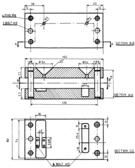
In conjunction with the screw extruder, special dies were designed and constructed for molding the RB on the projectile body (Fig. 2) and the tensile and compression test specimens used in material characterization (Figs. 3,4).
Fig 2. Special die used for molding the RB around the projectile body
Fig 3. Special die used for molding the tensile and compression test specimens
Fig 4. Tensile and compression test specimens used for material characterization
D. Test rig for measuring friction, wear and deformation of a RB at high sliding speeds
Montgomery measured the friction and wear of the RB material using a pin-on-disc type testing rig, but with a very short contact time in the range of 100 ms [5]. Experiments were made at a sliding speed of 1.7 m/s, corresponding to real projectile velocities. Wear rate was taken as the loss in pin length during the experiment.
the projectile is produced in the factory, by pressing a sample from each lot inside a portion of a barrel, using a universal testing machine, at a sliding speed of no more than 0.1 m/s. Fig. 5 shows the resisting force versus distance traveled at speeds of 0.00055 and 0.1 m/s in this type of static friction, wear, and deformation test. Three parameters are measured: the maximum force reached (Fmax), the steady-state force (Fss) during the sliding motion of the projectile, and the slope of the initial part of the curve (K).
Fig 5. Typical traces obtained in the static friction, wear and deformation test
The method used by Montgomery does not take into account the deformation of the RB (since processing variables usually affect the tribological properties), and also neglects the non-uniformity of wear throughout the length of the RB. On the other hand, the method used in production is conducted at very low speeds in comparison with those existing in practice.
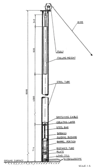
Therefore, a test rig is specially designed and constructed in order to simulate the real severe conditions the RB suffers during service. This rig is shown in Fig. 6, and consists of a falling weight used to drive the projectile into an actual portion of a real barrel. The RB deforms when going through the forcing cone of the barrel, then slides over the remaining part of the barrel until it is finally pulled out. The system allows a maximum falling height of four meters, which corresponds to a striking velocity of 8.9 m/s. The applied pressure at striking was calculated and estimated at 5 MPa. In this test, the friction force is detected by a compression load cell, and its output recorded by a storage oscilloscope triggered externally by a pulse generator. Traces were properly calibrated on a universal testing machine. Also, the wear of the RB was expressed by recording the dimensional changes after exiting the barrel.
E. Mechanical Properties Testing
Tensile and compressive tests were conducted according to ASTM-D-1708 [6] and ASTM-D-695 [7], at 23oC and at 1-1.3 mm/min and 1 mm/min, respectively. Five specimens were tested for each sample. The true stress- true strain curves were deduced for each specimen from the load-displacement traces obtained on an X-Y recorder. The following data were calculated: (a) strength at yield and at break; (b) Modulus of elasticity; (c) Strain at yield and at break.
III. RESULTS AND DISCUSSION
A. OFHC copper RB Reference material
Fig 6. Test rig used for the dynamic friction, wear, and deformation test
(a) Low-sliding speed friction, wear, and deformation Fig. 7 shows typical traces obtained at the sliding speed of 0.00055 m/s.
Fig 7. Typical traces from friction, wear and deformation test on copper RB at 0.00055 m/s.
From such traces, average values calculated were:
- Maximum resisting force, Fmax = 3400 kg- Steady-state resisting force, Fss = 1800 kg - Slope of initial part of the trace, K = 486 kg/mm
(b) High-sliding speed friction, wear, and deformation
Fig. 8 shows a test trace obtained using the testing rig of Fig. 6 at the sliding speed of 8.9 m/s.
Fig 8. Typical trace from friction, wear and deformation test on copper RB at 8.9 m/s. From such traces, average values calculated were: - Maximum resisting force, Fmax = 7750 kg - Steady- state resisting force, Fss = 1650 kg - Slope of initial part of the trace, K = 1107 kg/mm
Also, the coefficient of friction under these testing conditions was calculated at µdyn = 0.348 [8], which is smaller than µst, but close to the values reported by Montgomery [5].
B. Glass Fiber Reinforcement of PA (a) Compression Test Results
Fig. 9 shows that the addition of GF improves the yield and breaking strength and the modulus of elasticity of PA 66, but lowers its ductility.
Fig 9. Effect of GF content on compressive properties
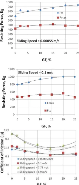
(b) Low-sliding speed friction, wear, and deformation GF contents used were: 0, 2, 5, 10, 15, 20, and 25%, while sliding speeds chosen were: 0.55 x 10⁻³ and 0.1 m/s. From the recorded traces, results were plotted in Fig. 10.
Fig 10. Effect of GF content and sliding speed on Fmax, Fss, and µ
The following remarks can be made:
• Recorded traces were similar to those obtained on copper specimens (Fig. 7 above)
• Fmax and Fss increase with GF content for both speeds
• µ decreases by increasing GF content up to 15%, then increases slightly; and generally increases with speed. Visual inspection of the test specimens before and after tests revealed:
• All specimens did not fail, except the specimen with 25% GF content at 0.1 m/s where cracks were clear inside the RB.
• No debris were found on the barrel bore at all speeds.
Specimen dimensions were measured after tests as reference against which the severe wear expected at high sliding speeds will be compared.
(c) High-sliding speed friction, wear, and deformation
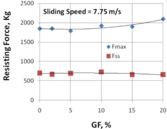
GF contents used were: 0, 2, 5, 10, 15, 20, and 25%, while sliding speeds chosen were: 7.75 and 8.9 m/s. From the recorded traces, sample results for the resisting forces are shown in Fig. 11.
Fig 11. Effect of GF content on resisting forces at 7.75 m/s
The following remarks are made:
• Recorded traces are similar to those obtained on copper specimens (Fig. 8 above). In the SS region, the RB seems to behave as a damped vibrating spring with possible slight stick-slip behavior.
• Fmax increases with GF content and sliding speed
• At 7.75 m/s, Fss slightly increases with GF content up to 10%, then slightly decreases; at 8.9 m/s, it continuously decreases.
• µ decreases by increasing GF content up to 15%, then increases slightly; and generally decreases with speed up to 15% GF content, then slightly increases (cf. Fig. 10).
Visual inspection of the test specimens before and after tests revealed:
• At 7.75 m/s, specimens with GF content >5% break during the test; at 8.9 m/s, specimens break when GF content is greater than 2%.
• Transferred layers were observed adhering to the bore.
Dimensions of specimens that did not fail were measured after tests and compared to the reference dimensions of specimens tested statically. Relevant observations are:
• Front parts of the RB wear more than the rear parts
• Rear parts of the RB increase in dimensions for the GF filled specimens
• At 8.9 m/s, all dimensions of unfilled PA66 RB decrease in value. The decrease is more than for the case of OFHC copper RB at the same conditions.
• The quantity of wear occurring in the grooves is much greater than that occurring in the lands for unfilled PA66
• Wear resistance is improved by GF reinforcement
• By increasing GF content above 5% for sliding speed of 7.75 m/s, and above 2% for sliding speed of 8.9 m/s, it is seen that the RB is completely destroyed.
IV. CONCLUSIONS
Experimental results indicate that 2% GF content as reinforcement to PA66 resin appears to be the ideal compromise. In this case, the wear resistance of PA66 resin is improved, and the RB withstands the associated plastic deformation without failure at all sliding speeds.
ACKNOWLEDGMENT
A. M. Eleiche would like to thank the staff of the Tribology Laboratory at the Faculty of Engineering, Cairo University for their support in conducting the tests, and King Fahd University of Petroleum and Minerals for providing necessary facilities for the preparation of this paper.
REFERENCES
[1] M. Eig, "Evaluation and critique on use of polymeric materials as rotating bands on 20mm projectiles," Technical Report 4358, Picatinney Arsenal, Dover, N.J., September, 1972.
[2] W. S. Larsen, R.B. Steidley, S.J. Bilsbury, and O.K. Heiney, "Development of a plastic rotating band for high performance projectiles, " AFATL-TR-74-106, July, 1974.
[3] R. S. Montgomery, “Interaction of copper-containing rotating band metal with gun bores at the environment present in a gun tube, Wear 33, pp. 109-128, 1975.
[4] M. D. Raby, “Effects of temperature and humidity on glass-reinforced nylon rotating bands”, M.S.C. thesis, Mechanical Engineering, Utah State University, 2010.
[5] R. S. Montgomery, “The sliding behaviors of copper alloys”, The International Conference on Wear of Materials, Washington, D.C., pp. 465-470, April 1983.
[6] ASTM, “Standard test methods for tensile properties of plastics by use of microtensile specimens”, 1975 Annual Book of ASTM Standards, Part 35, D-1798, USA
[7] ASTM, “Standard test methods for compressive properties of rigid plastics”, 1975 Annual Book of ASTM Standards, Part 35, D-695, USA