Operational Review of the First Wireline In Situ Stress
Test in Scientific Ocean Drilling
by Moe Kyaw Thu, Takatoshi Ito, Weiren Lin, Mai-Linh Doan, David Boutt, Yoshihisa Kawamura,
Chee Kin Khong, Lisa McNeill, Timothy Byrne, Demian Saffer, Eiichiro Araki, Nobu Eguchi,
Ikuo Sawada, Peter Flemings, Yasuyuki Kano, Casey Moore,
Masataka Kinoshita, and Harold Tobin
doi:10.2204/iodp.sd.13.06.2011
Introduction
Scientific ocean drilling’s first in situ stress measurement was made at Site C0009A during Integrated Ocean Drilling Program (IODP) Expedition 319 as part of Nankai Trough Seismogenic Zone Experiment (NanTroSEIZE) Stage 2. The Modular Formation Dynamics Tester (MDT, Schlumberger) wireline logging tool was deployed in riser Hole C0009A to measure in situ formation pore pressure, formation permea-bility (often reported as mopermea-bility=permeapermea-bility/viscosity), and the least principal stress (S3) at several isolated depths (Saffer et al., 2009; Expedition 319 Scientists, 2010).
The importance of in situ stress measurements is not only for scientific interests in active tectonic drilling, but also for geomechanical and well bore stability analyses. Certain in situ tools were not previously available for scientific ocean drilling due to the borehole diameter and open hole limits of riserless drilling. The riser-capable drillship, D/V Chikyu, now in service for IODP expeditions, allows all of the tech-niques available to estimate the magnitudes and orientations of 3-D stresses to be used. These techniques include down-hole density logging for vertical stress, breakout and caliper log analyses for maximum horizontal stress, core-based ane-lastic strain recovery (ASR, used in the NanTroSEIZE
expe-ditions in 2007–2008), and leak-off test (Lin et al., 2008) and minifrac/hydraulic fracturing (NanTroSEIZE Expedition 319 in 2009). In this report, the whole operational planning process related to in situ measurements is reviewed, and lessons learned from Expedition 319 are summarized for efficient planning and testing in the future.
Background
Borehole studies can provide information about vertical stress by downhole density logging, about minimum hori-zontal stress by extended leak-off test and hydraulic frac-turing, and about maximum horizontal stress by breakout analyses (Zoback et al., 2003). During the expeditions of NanTroSEIZE Stage 1, a transect of eight sites was drilled in the regions of the frontal thrust, the midslope megasplay fault, and the Kumano forearc basin using a full suite of Measurement While Drilling - Logging While Drilling (MWD-LWD), coring, and downhole measurements (Kinoshita et al., 2009; Moe et al., 2009). The overarching objective of the LWD program was to provide borehole data that will be used in conjunction with cores to document the geology, physical properties, mechanical state, fluid content, and stress conditions at the drill sites (Kinoshita et al., 2009). Preliminary experiments to determine the orien-
tations and magnitudes of principal stresses in the Nankai Trough were undertaken dur-ing the NanTroSEIZE Stage 1 expeditions using borehole image analysis (stress-induced breakouts and tensile fractures; Kinoshita et al., 2008) and indi-rect, core-based methods such as anelastic strain recovery about three-dimensional stress (Lin et al., 2006; Byrne et al., 2009). An extensive logging program at Site C0009A as part of NanTroSEIZE Stage 2 (Fig. 1) included conventional wireline logging in riser mode with formation stress meas- urements and a wide-angle Walkaway Vertical Seismic Profile (VSP) with the longest offset in scientific ocean
drill-Figure 1. Modular Formation Dynamics Tester (MDT) in operation and illustration of all logging runs from Expedition 319. Measurement While Drilling to total-depth was followed by five runs of wireline toolstrings.
(Front view)
(Rear view)
B
Pump-out Unit
Single Probe
Dual Packer
(10" outer diameter) Gamma Ray
Sonde
(20.21 m)
"
"
gauges measure the packer internal pressure and the pres-sure of the fluid between the packers (Carnegie et al., 2002) (Fig. 1).
The importance of strict criteria on borehole conditions and selecting target depths should be noted. Limitations for the MDT wireline tool include the following.
• a hole diameter within 29.21 cm (11.5 inches) and 37.47 cm (14.75 inches) for easy packer insertion and efficient inflation
• hole ovality (Dmax/Dmin) <130% for efficient packer sealing
• expected permeability of <1 mD for the HF test by seawater injection using standard pump and >0.1 mD for the drawdown test (for formation pore pressure and permeability measurement) to prevent no pressure buildup and poroelastic disturbance within the formation caused by too large permeability and too long drawdown test from too small permeability (Note: Permeability derived in the Expedition 319 was ~ 0.1 mD (Boutt et al., in press).)
• zone thickness of >3 m for the HF and >2 m for the drawdown test
• avoidance of pre-existing fractures for both tests.
• good mud cake formation to avoid super-charging and enabling reliable pore pressure measurement and single probe permeability testing
• good borehole stability since the tool is significantly larger than usual logging tools
A classic stress test procedure consists of a series of injec-tion stages or cycles as described below.
Packer inflation is meant to isolate the test interval and results in the pressure in the interval starting to rise after the tool has been properly positioned. A subsequent pres-sure decline is then observed to check the quality of the packer seal, with further pressurization if the seal is not satisfactory.
Leak-off cycles include injections of fluid into the interval at a constant flow rate. This pressurizes the wellbore below the breakdown of the formation to check that the downhole pump can deliver enough flow rate to overcome fluid diffu-sion through the mudcake and into the formation.
In the hydraulic fracturing cycles, fluid is again injected into the interval at a constant flow rate and up to the initiation of a tensile fracture, which is recognized either by a break-down or a pressure plateau. The fracture is then extended for 1–5 minutes before the interval is isolated and the pump stopped (shut-in), the pressure decline then observed, and then followed by a series of injection/fall-off cycles (two to ing (30 km) to improve velocity information of the deep plate
boundary and mega-splay faults—the ultimate targets of the project (Moe et al., 2009; Saffer et al., 2009; McNeill et al., 2010; Expedition 319 Scientists, 2010). In a vertical borehole, the orientation of breakouts is a well-established indicator of the orientation of the horizontal maximum principal stress in the present-day stress field (Zoback et al., 2003). Borehole breakouts have been used for stress estimation in NanTroSEIZE Stage 1 and previous expeditions on the Nankai margin (McNeill et al., 2004; Ienaga et al., 2006; Chang et al., 2010). This is the case for stress orientation but not for stress magnitude. Thus, for further understanding the state of stress, the hydraulic fracturing (HF) method was used to measure stress magnitude in Expedition 319 (Ito et al., 2009; Saffer et al., 2009; McNeill et al., 2010; Expedition 319 Scientists, 2010).
Data taken from HF measurements are not only scientifi-cally important but also necessary for operational planning of deep riser holes. In this regard, in situ stress is useful for geomechanical and wellbore stability studies. The Center for Deep Earth Exploration (CDEX) has collaborated with GeoMechanics International, Inc. on such studies since 2007 in pore pressure estimation using seismic traces extracted from the high-resolution 3-D seismic data cube (Moore et al., 2009) and calibrated using LWD data as well as geomechanical studies using logging and core analyses data taken from the NanTroSEIZE Stage 1 expeditions (Kinoshita et al., 2009). The absence of leak-off and hydraulic fracturing information in this preliminary study increases the uncertainty in estimating the fracture gradient, and hence can be inconsistent with wellbore failure observations (Castillo et al., 2008).
In Situ
Stress Measurement Methods
Stress magnitudes can be inferred from continuous logs (e.g., from sonic-based measurements), but these must be calibrated to obtain direct measurements of stress. At pres-ent, the only reliable and accurate measurements of in situ
five) to reopen, further propagate, and then close the frac-ture to both check the test is repeatable and possibly change the injection parameters (flow rate and injected volume).
Once the operator is satisfied that good quality data have been acquired, the packers are deflated, and the tool is moved to the next interval. A typical test can take from 20 minutes to 1.5 hours, depending on the number of injec-tion cycles that are performed (Desroches and Kurkjian, 1998).
Logging Planning and Operations for Site
C0009, Nankai Subduction Zone
A CDEX expedition team was formed in July 2008 follow-ing the schedulfollow-ing of Expedition 319, and loggfollow-ing plannfollow-ing began with assessment of several new tools for scientific ocean drilling, such as MDT, Formation MicroImager (FMI), SonicScanner and High-Resolution Laterolog Array (HRLA), and walkaway VSP (utilizing the Vertical Seismic Imager tool). The call for participation left relatively little time between initiating operations and logging planning and the start of the expedition. An MDT test was agreed upon with the condition that the hole stability was first confirmed by the drilling and the logging results of two wireline runs.
In the process of preparing the MDT measurement plan, four major steps (before and during the expedition) were
carried out. The first step was a series of seminars about the new tools and measurements, where expedition scientists attended and led the preparation for MDT draft measure-ment plan together with the CDEX Logging Staff Scientist (LSS) before expedition. The second step was working on details of measurement plan by logging scientists and Schlumberger engineers onboard with the LSS, Co-Chiefs (CCs), Expedition Project Manager (EPM), and operations geologists from CDEX. Daily updates were shared with the onshore LSSs, Co-chief Scientists, EPM and a Schlumberger MDT specialist. The third step was interpretation of wireline logs taken from logging runs prior to the MDT experiment. Caliper, FMI resistivity image, resistivity, gamma-ray, and sonic velocity logs were thoroughly examined to finalize the plan and select the target zones and depths for each test (Fig. 2). The fourth step was making final decisions on operational details in regard to safety among the onboard Executive Committee (i.e., Ship Captain, Operations Superintendent (OSI), EPM, CCs, and Offshore Installation Manager).
Major adjustments were made during steps onboard. From the cost factors, both dual packer HF tests and draw-down tests were reduced. For safety, the single probe tool was added to run together with the dual packer to reduce the risk of differential pressure sticking, for quick pore pressure and drawdown tests in the high or medium permeability formations, and for selection of dual packer test depths (ultimately providing fur-ther scientific data), This imposed a time limit for each MDT measurement.
After two runs of wire-line logging, logging scien-tists and chief scienscien-tists identified test depths from logs during a short time of wiper trip in the hole. As a primary focus was making tests in the cored section at the bottom of the hole (where sample analyses would complement the
in situ measurements), one
HF and one drawdown test were made within the cored section at ~1500 mbsf with the dual packer. In addition, one HF test was conducted in the shallower part of the borehole, travel-ing to the bottom of the hole and four tests on return, and two tests were conducted at the depths of the dual packer tests as a
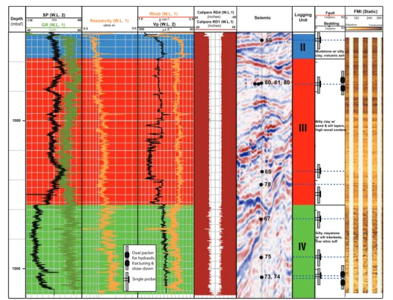
Figure 2. MDT test points on the seismic cross-section together with some important logging data and their interpretation. (From left to right) Depth (meter below seafloor, mbsf), wireline logging runs (W.L.) [spontaneous potential (SP), gamma-ray (GR)], resistivity, density (Rhob), p-wave velocity (Vp), EMS calipers, MDT test points on seismic, logging units from cuttings/core-log-seismic integration, dip picks from FMI data. and static-normalized FMI image.
II
III
IV
SP (W.L. 2) mv
-130 -90
40 GAPI 90
GR (W.L. 1) Resistivity (W.L. 1)
1.0 2.5
Rhob (W.L. 1)
Vp (W.L. 2)
5.0 50
ohm m
0.5
g cm-3
µsft-1
200
Logging Unit Seismic
1500 1000
Calipers RD4 (W.L.1)
20 -20
Calipers RD1 (W.L.1)
-20 (inches) 20
(inches) Depth
(mbsf)
Degrees
0 90
FMI (Static)
0 120 240 360
Resistive Conductive
Fault
Bedding
Degrees
0 90
59
60, 61, 80
65
78
67
75
73, 74
Figure 3. MDT test points on the seismic cross section together with some important logging data and their interpretation. (From left to right) Depth (meter below seafloor), wireline logging runs (W.L.), Spontaneous potential, gamma-ray
Dual packer for hydraulic fracturing & draw-down
Single probe
Mudstone w/ silty clay, volcanic ash
Silty clay w/ sand & silt layers, high wood content
pre-test check on the site selection (Fig. 2). These sites are distributed throughout the borehole to give a range of data in different environments and formations. The single probe provided critical data for selecting the final MDT sites (both for HF and permeability) and in evaluating risks, as well as providing additional data on formation pore pressure and permeability.
Summary
Deployment of the MDT tool deeper within the forearc and in the vicinity of major fault zones in future riser holes will constitute a major breakthrough in understanding sub-duction zone fault mechanics, and it is a critical part of the NanTroSEIZE program (Araki et al., 2009; Saffer et al., 2009; McNeill et al., 2010). Operation of this tool was com-plex both in the planning and execution phase, but valuable experience has been gained by both CDEX and NanTroSEIZE scientists. Unlike other logging measurements, MDT requires considerable involvement of the scientists during planning stage, in decision making during the experiment through real-time monitoring, and constant communication with the MDT specialist, engineer, and drilling operations team. The following factors summarized from the experi-ence and lessons learned from Expedition 319 should inform future MDT deployment on riser expeditions for efficient and scientifically reliable operations.
• A minimum of two LSSs are necessary for the logging operations of riser expeditions.
• Sufficient time is necessary for the dual packer test to generate useful results. A high-performance packer with auto retract mechanism may be an option for future experiments.
• Additional use of single probe at various depths was useful for range of scientific objectives: depth pro- file for hydrologic interpretation, evaluating the role of erosional and structural events on major transitions/unconformities, lithologic comparison, understanding how the deformation influences the permeability of accretionary prisms, and pore pressure estimation, which is a crucial parameter to understand the mechanics of the prism and décollement.
• Borehole imaging prior to and following the HF test is necessary to determine orientation of the fracture induced or activated by hydraulic fracturing.
Acknowledgements
Thanks are due to the marine and drilling crew of the
Chikyu and many others for their hard work for the success
of IODP Expedition 319. Funding from Ministry of Education, Culture, Sports, Science and Technology (MEXT), Japan, National Science Foundation (NSF), United States, and twenty-two other countries support this project as part of the
Integrated Ocean Drilling Program (IODP) for successful drilling in the Nankai Trough.
References
Araki, E., Byrne, T., McNeill, L., Saffer, D., Eguchi, N., Takahashi, K., and Toczko, S., 2009. NanTroSEIZE Stage 2: NanTroSEIZE riser/riserless observatory. IODP Sci. Prosp., 319. doi:10.2204/iodp.sp.319.2009.
Byrne, T.B., Lin, W., Tsutsumi, A., Yamamoto, Y., Lewis, J., Kanagawa, K., Kitamura, Y., Yamaguchi, A. and Kimura, G., 2009. Anelastic strain recovery reveals extension across SW Japan subduction zone. Geophy. Res. Lett., 36:L23310. doi:10.1029/2009/GL040749
Boutt, D., Saffer, D., Doan, M-L., Lin, W., Ito, T., Kano, Y., Flemings, P., McNeil, L., Byrne, T., and Moe, K.T., in press. Scale dependence of in situ permeability measurements in the Nankai accretionary prism: The role of fractures. Geophy.
Res. Lett.
Carnegie, A., Thomas, M., Efnik, M.S., Hamawi, M., Akbar, M., and Burton, M., 2002. An advanced method of determining in
situ reservoir stresses: Wireline conveyed micro-fracturing.
Soc. Petrol. Eng. Conference Paper, 78486-MS.
Castillo, D., Magee, M., and Dhakur, S., 2008. NanTroSEIZE Geomechanical analysis of the Stage 1 drilling and Data Acquisition Program: Phase 1. GeoMechanics International, Inc. (CDEX Internal Report).
Chang, C., McNeill, L.C., Moore, J.C., Lin, W., Conin, M., and Yamada, Y., 2010. In situ stress state in the Nankai accretionary wedge estimated from borehole wall failures. Geochem.
Geophys. Geosys., 11:Q0AD04. doi:10.1029/2010GC003261 Desroches, J., and Kurkjian, A.L., 1998. Applications of wireline
stress measurements. SPE Res. Eval. & Eng.,
2(5):451–461.
Expedition 319 Scientists, 2010. Expedition 319 summary. In Saffer, D., McNeill, L., Byrne, T., Araki, E., Toczko, S., Eguchi, N., Takahashi, K., and the Expedition 319 Scientists, Proc.
IODP, 319: Tokyo (Integrated Ocean Drilling Program Management International, Inc.). doi:10.2204/iodp.proc. 319.101.2010
Ienaga, M., McNeill, L.C., Mikada, H., Saito, S., Goldberg, D., and Moore, J.C., 2006. Borehole image analysis of the Nankai accretionary wedge, ODP Leg 196: Structural and stress studies. Tectonophysics, 426:207–220. doi:10.1016/j.tecto. 2006.02.018
Ito, T., Lin, W., Doan, M-L., Boutt, D., Kano, Y., Flemings, P., Ito, H., and IODP Expedition 319 Scientists, 2009. Outline of the in-situ stress tests using MDT tool at 2.7–3.6 km below sea level in the first riser hole on the NanTroSEIZE operation. [The 15th Formation Evaluation Symposium of Japan, 1–2 October 2009]. (extended abstract)
Kinoshita, M., Tobin, H., Moe, K.T., and the Expedition 314 Scientists, 2008. NanTroSEIZE Stage 1A: NanTroSEIZE LWD tran-sect. IODP Prel. Rept., 314. doi:10.2204/iodp.pr.314.2008 Kinoshita, M., Tobin, H., Ashi, J., Kimura, G., Lallemant, S., Screaton,
E.J., Curewitz, D., Masago, H., Moe, K.T., and the Expedition 314/315/316 Scientists, 2009. NanTroSEIZE Stage 1 expe-ditions: Introduction and synthesis of key results. Proc.
Drilling Program Management International , Inc.). Lin, W., Kwasniewski, M., Imamura, T., and Matsuki, K., 2006.
Determination of three-dimensional in situ stresses from anelastic strain recovery measurement of cores at great depth. Tectonophysics, 426:221–238. doi:10.1016/j.tecto. 2006.02.019
Lin, W., Yamamoto, K., Ito, H., Masago, H., and Kawamura, Y., 2008. Estimation of minimum principal stress from an extended leak-off test onboard the Chikyu drilling vessel and suggestions for future test procedures. Sci. Drill., 6:43–47. McNeill, L.C., Ienaga, M., Tobin, H., Saito, S., Goldberg, D., Moore,
J.C., and Mikada, H., 2004. Deformation and in situ stress in the Nankai Accretionary Prism from resistivity‐at‐bit images, ODP Leg 196. Geophys. Res. Lett., 31:L02602. doi:10.1029/2003GL018799
McNeill, L.C., Saffer, D., Byrne, T., Araki, E., Toczko, S., Eguchi, N., Takahashi, K., and Expedition 319 Scientists, 2010. IODP Expedition 319, NanTroSEIZE Stage 2: First IODP riser drilling operations and observatory installation towards understanding subduction zone seismogenesis. Sci. Drill., 10:4–13.
Moe, K.T., Sanada, Y., Kido, Y., Kawamura, Y., Cukur, D., Doan, M.-L., Kano, Y., et al., 2009. Overview of the NanTroSEIZE riser logging: Operational planning and reality. [The 15th Formation Evaluation Symposium of Japan, 1–2 October 2009]. (extended abstract)
Moore, G.F., Park, J.-O., Bangs, N.L., Gulick, S.P., Tobin, H.J., Nakamura, Y., Sato, S., et al., 2009. Structural and seismic stratigraphic framework of the NanTroSEIZE Stage 1 tran-sect. In Kinoshita, M., Tobin, H., Ashi, J., Kimura, G., Lallement, S., Screaton, E.J., Curewitz, D., Masago, H., Moe, K.T., and the Expedition 314/315/316 Scientists, Proc.
IODP, 314/315/316. doi:10.2204/iodp.
proc.314315316.102.2009
Saffer, D., McNeill, L., Araki, E., Byrne, T., Eguchi, N., Toczko, S., Takahashi, K., and the Expedition 319 Scientists, 2009. NanTroSEIZE Stage 2: NanTroSEIZE riser/riserless obser-vatory. IODP Prel. Rept., 319. doi:10.2204/iodp.pr.319.2009 Thiercelin, M.J., Plumb, R.A., and Desroches, J., 1996. A new wireline
tool for in situ stress measurements. SPE Format. Eval., 11(1):19–25.
Zoback, M.D., Barton, C.A., Brudy, M., Castillo, D.A., Finkbeiner, T. Grollimund, B.R., Moos, D.B., Peska, P., Ward, C.D., and Wiprut, D.J., 2003. Determination of stress orientation and magnitude in deep wells. Int. J. Rock Mech. Min. Sci., 40(7–8):1049–1076. doi:10.1016/j.ijrmms.2003.07.001
Authors
Moe Kyaw Thu, Nobu Eguchi, and Ikuo Sawada, Center
for Deep Earth Exploration (CDEX)—Japan Agency for Marine-Earth Science and Technology (JAMSTEC), 3173-25 Showa-machi, Kanazawa-ku, Yokohama, Kanagawa 236-0001, Japan, e-mail: moe@jamstec.go.jp.
Yoshihisa Kawamura, Ippan Shadan Hojin IODP-MI,
Tokyo University of Marine Science and Technology, Office of Liaison and Cooperative Research, 3rd Floor, 2-1-6
Etchujima, Koto-ku, Tokyo, 135-8533 Japan.
Chee Kin Khong, ECA Services Techniques Schlumberger,
Le Palatin 1, 1 cour du Triangle, 92936 La Defense –France.
Takatoshi Ito, Institute of Fluid Science, Tohoku University,
2-1-1 Katahira, Aoba-ku, Sendai, Miyagi 980-8577, Japan.
Weiren Lin, Kochi Institute for Core Sample Research,
Japan Agency for Marine-Earth Science and Technology, 200 Mononobe-Otsu, Nankoku, Kochi 783-8502, Japan.
Mai-Linh Doan, ISTerre Université de Grenoble 1, CNRS,
F-38041 Grenoble, France.
David Boutt, Department of Geosciences, University of
Massachusetts Amherst, 611 North Pleasant Street, 233 Morrill Center, Amherst, MA 01002, U.S.A.
Lisa McNeill, School of Ocean and Earth Science, National
Oceanography Centre, Southampton, University of Southampton, Southampton SO14 3ZH, U.K.
Demian Saffer, The Pennsylvania State University, 0310
Deike Building, University Park, PA 16802, U.S.A.
Eiichiro Araki, Earthquake and Tsunami Research Project
for Disaster Prevention, Japan Agency for Marine-Earth and Technology, 2-15 Natsushima-cho, Yokosuka, Kanagawa 237-0061, Japan.
Timothy Byrne, Center for Integrative Geosciences,
University of Connecticut, U-2045, 354 Mansfield Road, Storrs, CT 06269, U.S.A.
Yasuyuki Kano, Disaster Prevention Research Institute,
Kyoto University, Gokasho, Uji 611-0011, Japan.
Peter Flemings, Institute for Geophysics, Jackson School of
Geosciences, University of Texas at Austin, 10100 Burnet Road (R2200), Austin, TX 78758-4445, U.S.A.
Casey Moore, University of California Santa Cruz, 1156
High Street, Santa Cruz, CA 95064, U.S.A.
Masataka Kinoshita, Institute for Research on Earth
Evolution, Japan Agency for Marine-Earth Science and Technology, 2-15 Natsushima-cho, Yokosuka, Kanagawa 237-0061, Japan.
Harold Tobin, Department of Geology and Geophysics,
University of Wisconsin-Madison, 1215 West Dayton Street, Madison, WI 53706, U.S.A.
Related Web Links
ht t p://w w w.j a mst e c .go.jp/ch i k y u/en g/ E x p ed it ion/ NantroSEIZE/exp319.html
ht tp://publications.iodp.org/preliminar y_repor t/319/ index.html
http://publications.iodp.org/proceedings/319/103/103_. htm