S. de Miranda et alii, Frattura ed Integrità Strutturale, 29 (2014) 293-301; DOI: 10.3221/IGF-ESIS.29.25
293
Focussed on: Computational Mechanics and Mechanics of Materials in Italy
A simple beam model to analyse the durability of adhesively bonded
tile floorings in presence of shrinkage
S. de Miranda, A. Palermo, F. Ubertini
University of Bologna
[email protected], [email protected], [email protected]
ABSTRACT. A simple beam model for the evaluation of tile debonding due to substrate shrinkage is presented. The tile-adhesive-substrate package is modeled as an Euler-Bernoulli beam laying on a two-layer elastic foundation. An effective discrete model for inter-tile grouting is introduced with the aim of modelling workmanship defects due to partial filled groutings. The model is validated using the results of a 2D FE model. Different defect configurations and adhesive typologies are analysed, focusing the attention on the prediction of normal stresses in the adhesive layer under the assumption of Mode I failure of the adhesive.
KEYWORDS. Tile flooring; Tile debonding; Adhesive joint; Elastic foundation.
INTRODUCTION
ile floorings are extensively used in residential and industrial buildings. A typical tiled floor consists of an upper layer of tiles separated by grouting interfaces and attached via an adhesive stratum to a lower cementitious substrate (Fig. 1). Although tile floorings guarantee high resistance and durability also in severe exposure conditions, they are prone to suffer from debonding failure, typically induced by differential elongation/shortening between tile layer and substrate. The differential deformation may be caused by substrate shrinkage, either due to thermal gradients or residual maturation of cementitious substrate. Substrate shrinkage determines an eccentric compression in the tiles transferred by a shear mechanism through the adhesive layer. The inherent eccentricity of compression due to the geometric configuration of the tiled floor, eventually increased by the presence of grouting defects due to poor workmanship, may induce tile debonding due to Mode I failure of the adhesive layer.
Nowadays several types of adhesives are available in the market with increasing performance in terms of strength and deformation capacities at the prize of increasing costs. Therefore, for a cost-effective design of the tile flooring systems it is of fundamental importance an assessment of the stress state of the adhesive layer induced by the differential deformations.
S. de Miranda et alii, Frattura ed Integrità Strutturale, 29 (2014) 293-301; DOI: 10.3221/IGF-ESIS.29.25
294
by Cocchetti et al. [6]. The authors modelled a tile bonded to a rigid substrate through an elastic adhesive as an eccentrically compressed beam on a Pasternak foundation. The eccentricity of compression is induced by the presence of an out-of-plane workmanship defect leading to a Mode I failure of the adhesive. This approach leads to closed-form estimation of the ultimate strength of tile-substrate adhesive joint. More recently the use of simplified beam model with elastic constraints has been successfully applied also for the estimation of crack opening area in longitudinally cracked pipes [7, 8].
In the present paper, a simple beam model is developed to evaluate the stress state of tiled floors subjected to debonding due to substrate shrinkage. Then, an ad-hoc finite element is developed in order to solve the governing differential equations of the tile-adhesive-substrate system. The presence of inter-tile grouting is modelled through rotational/translational springs. The additional eccentricity induced by workmanship defects is taken into account by means of a partial/eccentric grouting modeled with the same rotational/translational springs collocated in eccentric position. Numerical analyses are performed on different tiled flooring configurations. The robustness and reliability of the proposed model is verified by comparing the model results in terms of normal stresses within the adhesive layer with those obtained with a 2D FE model developed with the commercial software Abaqus.
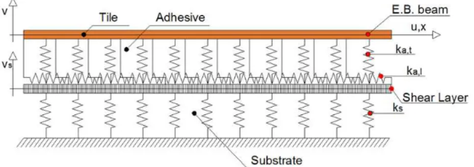
Figure 1: Tile flooring.
MECHANICAL MODEL
s regards the tile-adhesive-substrate system, reference is made to the mechanical model shown in Fig. 2. Grouting modelling will be described in the next section. The tile, bonded to the flexible substrate by means of an elastic adhesive, is modelled as an Euler-Bernoulli beam on a Pasternak foundation connected to a second layer of vertical springs by means of a shear deformable layer. The adoption of a two-layer system with an interposed shear deformable stratum is inspired by the model developed by Kerr [9] in the contest of geotechnical engineering.
Figure 2: Mechanical Model.
In the following, u x( ) and v x( ) denote the longitudinal (axial) and the transversal displacement of the tile respectively, and v xs( ) the transversal displacement of the substrate. Moreover, the Young modulus, the Poisson ratio and the thickness of material i are denoted by Ei, i, ti, respectively. Subscript i can become t, a, or s if the quantity refers to tile, adhesive or substrate, respectively. Plane strain conditions are assumed and, thus, for a material i the plane strain
modulus * i
i 2
i
E
E
1 ν
is used. Indeed, this hypothesis does not consider some specific features related to the
S. de Miranda et alii, Frattura ed Integrità Strutturale, 29 (2014) 293-301; DOI: 10.3221/IGF-ESIS.29.25
295
debonding of tile flooring (see e.g. [6]). With this notation, the stiffness coefficients of the springs modelling the adhesive
are expressed as
* ,
a a t
a
E k
t
and , a
a l a
G k
t
for the transverse and the longitudinal springs respectively, while, as regards
the substrate, it follows
*
s s
s
E k
t
. No vertical loads are applied to the flooring, self-weight is neglected and constant
substrate shrinkage 0 is imposed.
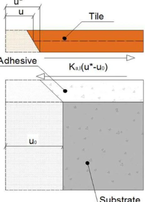
The assumed axial deformed configuration of the flooring due to substrate shrinkage is shown in Fig. 3. The imposed substrate shrinkage 0 induces a displacement u0 along the substrate height, which, in turn, induces a tile compression acting at the interface between adhesive and tile (i.e. eccentric with respect to tile axis). This compression is equal to
*
, 0
a l
k u u , where u* denotes the longitudinal displacement at the bottom position of the tile. According to the classical Euler-Bernoulli hypothesis, u* can be expressed as follows:
* '
2
t
t
u u v (1)
where v' denotes the derivative of v with respect to tile axis direction.
Of course, the above assumption leads to a coupled axial-flexural response of the tile. In this regard, it should be noted that a beam on a Pasternak foundation has been already used by Cocchetti et al. [6] to model tile debonding with a simple but effective mathematical formulation which does not account for the inherent eccentricity due to the geometrical configuration of the system. In the present work, by considering the eccentric position of the compression transferred by the adhesive to the tile, the coupled axial-flexural response of the tile is recovered. Furthermore, the assumption of flexible substrate, modeled as a layer of vertical springs interconnected by a shear layer, allows to enrich the model still preserving its formulation relatively simple.
Figure 3: Longitudinal interaction forces at tile-adhesive interface due to substrate shrinkage.
The potential energy Π of the tile-adhesive-substrate system can be expressed as:
T A S
Π Π Π Π (2)
S. de Miranda et alii, Frattura ed Integrità Strutturale, 29 (2014) 293-301; DOI: 10.3221/IGF-ESIS.29.25
296
* ' 2 * '' 2 T
1
Π
2 t t t
L
E A u E I v dx
(3)2
2 '
A , , 0
1
Π
2 2
t a t a l
L
t
k v k u v u dx
(4)
2 '2S
1
Π
2 s s s s s
L
k v v G A v dx
(5)In the above equations, A , t I ,t G and s As are the tile cross section area, the tile moment of inertia, the substrate shear modulus and the substrate cross section area, respectively.
As it can be noted, the potential energy Π T of the tile consists of the classical Euler-Bernoulli energy terms, the potential energy of the adhesive ΠA collects all the terms of the Pasternak formulation and the coupling terms and the substrate potential energy ΠS collects the elastic energy of the vertical springs and of the shear layer.
FINITE ELEMENT DISCRETIZATION
Tile-Adhesive-Substrate
tandard shape functions are used to represent the axial and transversal displacement fields u x v x
, of the tile andthe transversal displacement field v xs
of the substrate:
u
v s
vs su x N u v x N v v x N v (6)
where Nu, Nv and
s
v
N collect linear Lagrangian, cubic Hermitian and cubic Lagrangian shape functions, respectively,
and u , v , vs are vectors collecting nodal parameters.
With these assumptions, following standard procedures, the discrete equilibrium equations are derived:
KU P (7)
with: T T 0 0 0 s
s s s
uu uv u
uv vv vv v
s vv v v
K K u P
K K K K U v P P
v K K (8)
The expressions of the different submatrices of K and of the nodal load vectors Pu, Pv are given in Appendix.
Grouting-Adhesive-Substrate
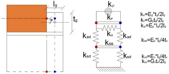
Grouting is modeled by means of a discrete approach based on the use of elastic springs as shown in Fig. 4. The grouting itself is modeled by an axial spring ku, a vertical transversal spring kv and a rotational spring k. The axial spring can be
placed in an eccentric position with respect to tile axis in order to account for partial-eccentric grouting configurations. The attached portion of the adhesive layer is modeled with two vertical springs kad while the related portion of substrate is modeled with two vertical springs ksd and a transversal spring kg.
The definition of each stiffness coefficient is reported in Fig. 4.
From the above discrete model, the definition of a grouting-adhesive-substrate stiffness matrix Kg is straightforward. The rationale to adopt a discrete approach for modelling inter-tile grouting is twofold: on the one hand the discrete approach allows a simple definition and straightforward implementation of the grouting stiffness matrix Kg, on the other hand it allows to preserve all the fundamental stiffness properties of the grouting (axial, transverse and rotational
S. de Miranda et alii, Frattura ed Integrità Strutturale, 29 (2014) 293-301; DOI: 10.3221/IGF-ESIS.29.25
297
stiffness). In this regard, in the work by Lignola et al. [6] the authors highlighted the influence of tile-joint details on the adhesive stress distribution and the need to account for these details. Moreover, the use of the proposed discrete approach allows to account for the presence of partial/eccentric inter-tile groutings that are a common typology of workmanship defects in tiled floors.
Figure 4: Grouting-Adhesive-Substrate discrete model.
NUMERICAL RESULTS
Case study
n this section some numerical examples are presented to show the capability of the proposed model to predict the response of a flooring system subjected to substrate shrinkage.
The analysed flooring system is composed of 8 tiles with interposed groutings laying on an adhesive stratum attached to the substrate (Fig. 5). The mechanical and geometrical properties of the flooring are listed in Tab. 1.
The presence of a localized defect is assumed by considering two different grouting configurations located at midspan of the flooring (Fig. 5):
- Partial Grouting Bottom (PGB): partial grouting in low eccentric position with respect to the tile axis; - Partial Grouting Top (PGT): partial grouting in high eccentric position with respect to the tile axis.
In addition, the case with no defects (FG) has been considered. Details of the partial grouting configurations are given in Tab. 2.
Length [mm] Thickness [mm] E [GPa] ν
Tile 600 8 49 0.18
Adhesive 4848 3 6.5 0.22
Substrate 4848 40 30.7 0.21
Grouting 6 8 19 0.2
Table 1: Case study. Geometrical and mechanical parameters.
For the PGB configuration, two different grouting lengths (2 mm and 6 mm) have been considered. In all the analysed cases, uniform substrate shrinkage 0 5 104 mm/mm is imposed along the substrate longitudinal direction. The chosen value of substrate shrinkage is a typical value for concrete structures [10].
S. de Miranda et alii, Frattura ed Integrità Strutturale, 29 (2014) 293-301; DOI: 10.3221/IGF-ESIS.29.25
298
As usual in a Kerr-like foundation [11], for the substrate an effective shear area As* is calibrated. For the proposed model,
an effective shear area * 10
s s
A
A has been numerical calibrated for the tile configurations described above and validated
through the parametric study developed in the next section.
The same flooring configurations (FG, PGB, PGT) have been modelled with 2D FE models, developed using the commercial software Abaqus. The solutions provided by the 2D FE models are taken as a reference to validate the results of the proposed model.
Attention is focused on the distribution of normal stresses in the adhesive, in accordance with the fact that the most typical failure condition of the flooring is determined by a Mode I failure mechanism of the adhesive layer.
Figure 5: The flooring system and the grouting configurations.
Length [mm] Thickness [mm] Eccentricity [mm]
PGB 2-6 2 -3
PGT 2 2 3
Table 2: Grouting configurations: geometrical dimensions.
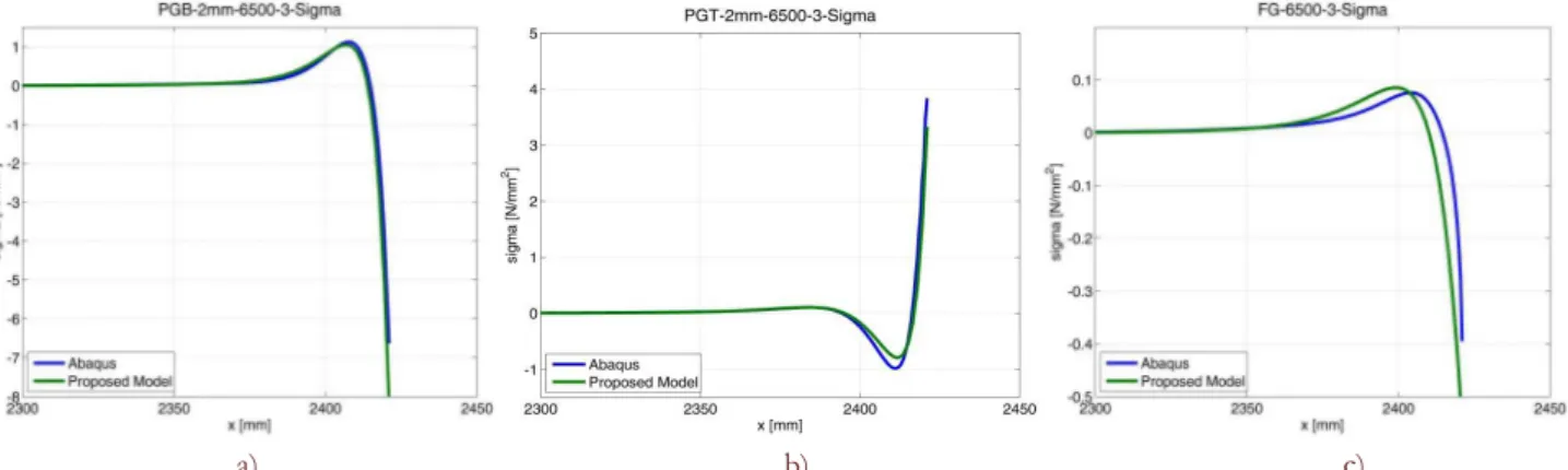
Fig. 6a, 6b and 6c compare the normal stresses in the adhesive layer close to the defect location as obtained from the proposed model and the 2D FE models for the three different grouting configurations PGB, PGT and FG, respectively. Inspecting the graphs reveals the good capability of the model in predicting the adhesive normal stress distribution. In particular, the peak tensile stress that could induce the initiation of the debonding mechanism is accurately evaluated for both the PGT and PGB configurations (Fig. 6a, Fig. 6b). As far as the FG case is concerned (Fig. 6c), it is worth noting that the proposed model is still able to accurately predict the normal stresses of the adhesive thanks to the assumed coupled axial-to-flexural response.
a) b) c)
Figure 6: Adhesive normal stress distribution at defect location. a) PGB configuration (grouting 2 mm length ), b) PGT configuration,
S. de Miranda et alii, Frattura ed Integrità Strutturale, 29 (2014) 293-301; DOI: 10.3221/IGF-ESIS.29.25
299
Parametric study
The elastic properties (E and ν) and the thickness of the adhesive layer have been varied in order to assess the robustness of the proposed simplified model. Ranges of variation are reported in Tab. 3. A total of 40 different cases have been analysed and compared with the results of the 2D FE models.
Adhesive
Thickness [mm] E [GPa] ν
3-5
3.5 0.3
5 0.25
6.5 0.22
8.0 0.18
10 0.175
Table 3:Adhesive elastic parameters and thicknesses.
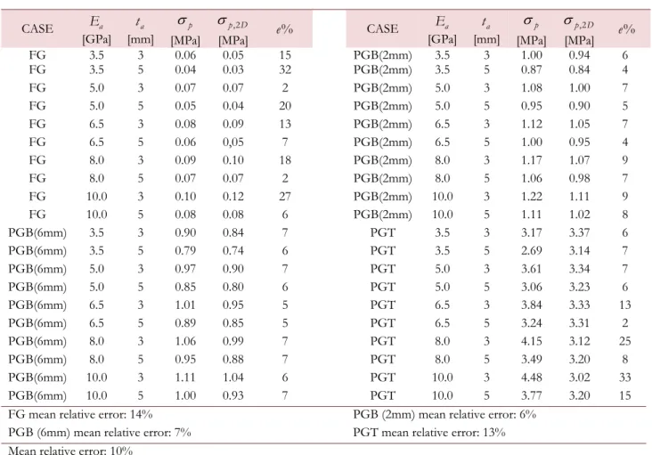
Tab. 4 lists the peak tensile stresses in the adhesive layer as obtained from the proposed model (p) and from the 2D FE
models (p D,2 ) for all the analysed cases.
It can be observed that the proposed approach shows an adequate robustness and reliability in predicting the peak tensile stress in the adhesive layer, resulting in a mean error equal to the 10%. The accuracy of the proposed model is clearly higher for medium stiff adhesive (6.5 GPa) for which the effective shear area As* has been calibrated and deteriorates only for very stiff or very flexible adhesive configurations, less common in actual flooring applications. Moreover, it is worth noting that for the most common defect typology, the PGB configuration, the accuracy of the proposed model is high for all the analysed cases (mean error ~ 6%).
CONCLUSIONS
simple beam model to analyse tile flooring debonding due to substrate shrinkage has been presented. In particular, a beam model on a two-layer foundation has been adopted to model the tile-adhesive-substrate system. Inter-tile grouting has been modeled by means of a discrete approach based on elastic springs, able to model both full and partial/eccentric grouting configurations. The results of the proposed model have been compared with those of 2D FE models.
The attention has been focused on the evaluation of the adhesive normal stress distribution, with the final aim of evaluating tile debonding due to Mode I failure mechanism of the adhesive layer. Numerical results have shown that the model allows an accurate evaluation of the stress state in the adhesive layer. Further efforts could be devoted to extend the proposed model for the inelastic analyses of floorings and to consider the presence of adhesion defects at the tile to substrate interface.
S. de Miranda et alii, Frattura ed Integrità Strutturale, 29 (2014) 293-301; DOI: 10.3221/IGF-ESIS.29.25
300
CASE Ea [GPa] a t [mm] p [MPa] ,2 p D
[MPa] e% CASE
a E [GPa] a t [mm] p [MPa] ,2 p D
[MPa] e%
FG 3.5 3 0.06 0.05 15 PGB(2mm) 3.5 3 1.00 0.94 6
FG 3.5 5 0.04 0.03 32 PGB(2mm) 3.5 5 0.87 0.84 4
FG 5.0 3 0.07 0.07 2 PGB(2mm) 5.0 3 1.08 1.00 7
FG 5.0 5 0.05 0.04 20 PGB(2mm) 5.0 5 0.95 0.90 5
FG 6.5 3 0.08 0.09 13 PGB(2mm) 6.5 3 1.12 1.05 7
FG 6.5 5 0.06 0,05 7 PGB(2mm) 6.5 5 1.00 0.95 4
FG 8.0 3 0.09 0.10 18 PGB(2mm) 8.0 3 1.17 1.07 9
FG 8.0 5 0.07 0.07 2 PGB(2mm) 8.0 5 1.06 0.98 7
FG 10.0 3 0.10 0.12 27 PGB(2mm) 10.0 3 1.22 1.11 9
FG 10.0 5 0.08 0.08 6 PGB(2mm) 10.0 5 1.11 1.02 8
PGB(6mm) 3.5 3 0.90 0.84 7 PGT 3.5 3 3.17 3.37 6
PGB(6mm) 3.5 5 0.79 0.74 6 PGT 3.5 5 2.69 3.14 7
PGB(6mm) 5.0 3 0.97 0.90 7 PGT 5.0 3 3.61 3.34 7
PGB(6mm) 5.0 5 0.85 0.80 6 PGT 5.0 5 3.06 3.23 6
PGB(6mm) 6.5 3 1.01 0.95 5 PGT 6.5 3 3.84 3.33 13
PGB(6mm) 6.5 5 0.89 0.85 5 PGT 6.5 5 3.24 3.31 2
PGB(6mm) 8.0 3 1.06 0.99 7 PGT 8.0 3 4.15 3.12 25
PGB(6mm) 8.0 5 0.95 0.88 7 PGT 8.0 5 3.49 3.20 8
PGB(6mm) 10.0 3 1.11 1.04 6 PGT 10.0 3 4.48 3.02 33
PGB(6mm) 10.0 5 1.00 0.93 7 PGT 10.0 5 3.77 3.20 15 FG mean relative error: 14% PGB (2mm) mean relative error: 6%
PGB (6mm) mean relative error: 7% PGT mean relative error: 13% Mean relative error: 10%
Table 4:Peak tensile stresses p, p D,2 and relative errors.
APPENDIX
n the following the expressions of the submatrices K ,uu K , uv K , vv Kvvs, Kvvsand the nodal load vectors P ,u P v are given:
' T * '
, d
uu u t t u u a l u L
E A k x
T K N N N N (A. 1)
T '
, d
2
t uv u a l v
L
t
k x
K N N (A. 2)
2
' T * ' ' T ' T
, , d
4
t
vv v t t v v a l v v a t v L
t
E I k k x
K N N N N N N (A. 3)
T
, d
s s
vv v a t v L
k x
K N N (A. 4)
T T 'T *
, ' d
s s s s s s s
v v v s v a t v v s s v L
k k G A x
K N N Nvs N N N (A. 5)
S. de Miranda et alii, Frattura ed Integrità Strutturale, 29 (2014) 293-301; DOI: 10.3221/IGF-ESIS.29.25
301
' T
, 0 d
u u a l L
k u x
P N (A. 6)
' T
, 0
' d
2
t
v v a l
L
t
k u x
P N (A. 7)
The imposed displacement u0 is evaluated from 0 corrected by the factor
*
* *
(1 t t )
t t s s
E t E t E t
to take into account the
substrate-tile axial deformability.
REFERENCES
[1] Williams, J., Hadavinia, H., Analytical solution for cohesive zone models, Journal of the Mechanics and Physics of Solids, 50 (2002) 809-825.
[2] Schmidt, P., Edlund, U., Analysis of adhesively bonded joints: a finite element method and a material model with damage, International Journal for Numerical Methods in Engineering, 66 (2006) 1271-1308.
[3] Goncalves, J. P. M,. de Moura, M. F. S. F., de Castro, P. M. S. T., A three-dimensional finite element model for stress analysis of adhesive joints, International Journal of Adhesion & Adhesives, 22 (2002) 357–365.
[4] Mahaboonpachai, T., Matsumoto, T., Inaba, Y., Investigation of interfacial fracture toughness between concrete and adhesive mortar in an external wall tile structure, International Journal of Adhesion and Adhesives, 30 (2010) 1-9. [5] Lignola, G.P., Collina, A., Prota, A., Manfredi, G., Analysis of tile-substrate behavior subjected to shrinkage, 19
AIMETA Conference, September 2009, paper # 129.
[6] Cocchetti, G., Comi, C., Perego, U., Strength assessment of adhesively bonded tile claddings, International Journal of Solids and Structures, 48 (2011) 2048-2059.
[7] de Miranda, S., Molari, L., Scalet, G., Ubertini, F., Simple beam model to estimate leakage in longitudinally cracked pressurized pipes, ASCE Journal of Structural Engineering, 138 (2012) 1065-1074.
[8] de Miranda, S., Molari, L., Scalet, G., Ubertini, F., A physically-based analytical relationship for practical prediction of leakage in longitudinally cracked pressurized pipes, submitted to Engineering Structures.
[9] Kerr, A. D., A Study of a New Foundation Model, Acta Mechanica, 1 (1965) 135-147.
[10]ACI Committee 209, Guide for Modeling and Calculating Shrinkage and Creep in Hardened Concrete, (2008)