EFFICIENCY INCREASE IN SHIP'S PRIMAL ENERGY SYSTEM
USING A MULTISTAGE COMPRESSION WITH INTERCOOLING
by
Petar LANDEKA and Gojmir RADICA* Faculty of Electrical Engineering, Mechanical Engineering
and Naval Architecture, Split, Croatia
Original scientific paper DOI: 10.2298/TSCI140310117L
This paper focuses on an analysis of the potential increase of efficiency in ship's primal energy system using a turbocharger with multistage compression with in-tercooling, and diverting a greater flow of exhaust gases to power turbine of waste heat recovery system. Analysis of potential efficiency increase has been made for various stages of compression for a 100% main engine load, and an analysis of five stage compression with intercooling for a main engine load be-tween 50% and 100%.
Key words: waste heat recovery system, Diesel engine, turbocharger
Introduction
Turbine technology has been approved and widely adopted on ships. Higher engine efficiency, lower NOx and CO2 emissions are among the key drivers of marine Diesel engine development. Higher engine efficiency is yielded by higher turbocharger efficiencies from two-stage turbocharging along with a more optimum division between compression and ex-pansion strokes from the Miller cycle [1].
Saidur et al. [2], has identified that there are large potentials for energy savings through the use of waste heat recovery (WHR) technologies. The WHR entails capturing and reusing the waste heat from internal combustion engine and using it for heating or generating mechanical or electrical work. Aly [3] estimated that the heat recovered from Diesel engine exhaust gases can be used to obtain an additional 15-16% increase in the total power output. Shu et al. [4] per-formed a detailed analyse of WHR technologies on ships. These technologies include turbine, re-frigeration, Rankine cycle, desalination, and combined cycle systems using more than two of these WHR technologies. Medica et al. [5] investigated turbocharger performance and efficiency reduction when the compressor’s operating point approaches the surging limit due to heavy seas and in the event of contamination. More than 15% of fuel energy is lost as waste heat in scav-enge air coolers. A typical turbocharger compresses air in one stage, after which the air is cooled to about 312 K before engine intake. In this case, excluding the main engine and a turbocharger, a WHR system which produces electricity, then about 10% of exhaust gases, which would usual-ly go to the turbocharger, are diverted to the power turbine of the WHR system, decreasing the pressure of scavenge air [6]. The purpose of this study is to provide an analysis of potential effi-ciency increase in ship's energy system using a multistage compression with intercooling in a turbocharger, and diverting a greater flow of exhaust gases to the WHR system power turbine. This would leave us with the option of scavenge air pressure optimisation.
––––––––––––––
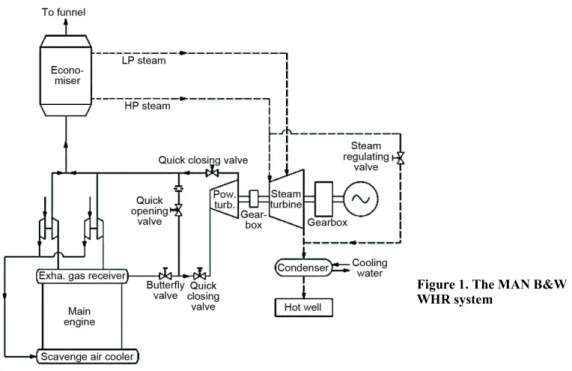
er turbine, economiser, and the steam turbine. About 10% of exhaust gases flow is diverted to produce usable mechanical work in WHR system's power turbine which is connected via the gearbox to the steam turbine. Exhaust gases, after the turbocharger and power turbine, enter the economiser where they exchange heat for steam production. Steam flows to the steam tur-bine where it produces usable mechanical work and converts it to electricity in a generator, [7]. Figure 1 is remade schematic of WHR system used by MAN B&W.
Figure 1. The MAN B&W WHR system
Theory and calculations
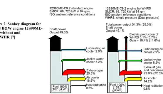
If we look at waste heat data, we can observe that air cooler heat amounts to about 15% of fuel energy (fig. 2, tab. 1). This is a result of high scavenge air pressure 3-4 bar at higher main engine loads [7-9].
Figure 2. Sankey diagram for MAN B&W engine 12S90ME-C9.2 without and
with WHR [7]
resulting in possible exhaust gases flow reduction to turbocharger and exhaust gases flow boost to the power turbine of the WHR system and efficiency increase of the WHR system.
Official data provided by engine manufacturer allows us to calculate the polytrophic compression coefficient. According to official data, electricity produced accounts for 80% and 100% main engine load [9]. This data can be transformed into an efficiency increase of the ship's primal energy system. As we have only those two sets of data, we need to make another assumption that the efficiency increase behaves linearly relative to main engine load. In order to make a model with existing data we use the following assumptions:
– polytrophic coefficient, and with it compressor small stage efficiency, is the same in the used as in the proposed compressor of turbocharger,
– all heat in the compression process is friction heat, there is no heat exchange (adiabatic process) with the surroundings,
– intake air has ISO standard properties,
– air is cooled to 312 K in the intercooler section, because of a sufficient temperature differ-ence between compressed air and cooling water,
– air properties are constant relative to temperature,
– turbocharger turbine efficiency is equivalent to power turbine efficiency so all the work that is saved by multistage compression with intercooling in relation to single stage com-pression is transferred to an electric generator via power turbine, and
– proposed model works with the same air pressure and temperature at engine air intake sim-ilar to the main engine with a typical turbocharger.
ISO condition; Ambient air, 25.0 °C; Scavenge air coolant, 25.0 °C Loads below 35% are associated with larger tolerances
1 – Engine load [% of SMCR]; 2 – Engine power [kW]; 3 – Engine speed [rpm]; 4 – Scavenge air amount [kg/h] ± 5%; 5 – Scavenge air pressure [bar abs]; 6 – Scavenge air temperature before cooler [°C]; 7 – Scavenge air temperature after cooler [°C]; 8 – Scavenge air cooler heat [kW]; 9 – Jacket water cooler heat [kW]; 10 – Main lubrication oil heat [kW]; 11 – Condensed water [t/24 h]
air
0 1
0 1
1
ln ln
1
ln ln
n
T T
p p
=
−
− −
(1)
Equation (1) is derived from a standard relation of pressures, temperatures and a polytrophic coefficient:
compr_r p( 1 0)
w =c T −T (2)
Equation (2) presents compression work as a difference of enthalpy because there is no heat exchange in the process:
100 81,340 84.0 634,500 4.25 212 37 31,150 9,870 5,670 0.0
95 77,273 82.6 613,000 4.05 205 36 29,000 9,510 5,600 0.0
90 73,206 81.1 591,000 3.84 197 34 26,840 9,140 5,510 0.0
85 69,139 79.6 568,200 3.64 188 33 24,670 8,780 5,420 0.0
80 65,072 78.0 544,400 3.43 180 32 22,480 8,410 5,310 0.0
75 61,005 76.3 519,400 3.23 171 31 20,280 8,040 5,200 0.0
70 56,938 74.6 493,200 3.02 161 30 18,070 7,680 5,070 00
65 52,871 72.8 465,500 2.82 151 30 15,870 7,310 4,920 0.0
60 48,804 70.8 436,300 2.61 141 29 13,690 6,940 4,770 0.0
55 44,737 68.8 405,700 2.41 130 28 11,550 6,580 4,600 0.0
50 40,670 66.7 373,600 220 118 27 9,470 6,210 4,410 0.0
45 36,603 64.4 340,100 2.00 106 27 7,520 5,840 4,210 0.0
40 32,536 61.9 305,200 1.82 94 27 5,780 5,480 3,990 0.0
35 28,469 59.2 269,100 1.66 83 26 4,260 5,110 3,740 0.0
30 24,402 56.2 278,000 1.51 72 33 3,570 4,750 3,480 0.0
25 20,335 52.9 234,800 1.38 61 33 2,360 4,380 3,180 0.0
20 16,268 49.1 199,900 1.27 52 32 1,490 4,010 2,850 0.0
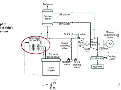
Figure 3. Concept of improved model of ship's primal energy system
1
0 z p
p
ε = (3)
Equation (3) presents compression ratio of one stage in multistage compression as a zth root (z is the number of stages) of total compression ratio:
air air
1
st.1 0 n
n
T Tε
−
= (4)
air air
1
st.2 cool n
n
T T ε
−
= (5)
Equations (4) and (5) are standard relations of temperatures, one stage compression ratio, and a polytrophic coefficient:
compr_r_multistage p[( st.1 0) ( 1)( st.2 cool)]
w = c T −T + z− T −T (6)
Equation (6) presents compression work as an added difference of enthalpy of all stages of compression, because there is no heat exchange in the process. In the first stage of compression, air temperature is 298 K, but in all other compression stages air has a different temperature at the start of compression:
compr compr_r compr_r_multistage
w w w
∆ = − (7)
Equation (7) presents the assumption that all saved work in a turbocharger compres-sion is transferred to the power turbine:
compr gen increase
f&o
w
E
η
η = ∆ (8)
overall main_engine WHR increase
η =η +η +η (9)
Figure 4 shows the ship's primal energy system efficiency increase of 2% for two stage compression, and efficiency increase approach-es 3.6% as we increase the number of stagapproach-es. This data is valid for a 100% main engine load.
It is necessary to determine an optimal number of compression stages, in which in-vestment cost and specific fuel consumption re-duction due to overall efficiency increase will be compared. Five stage compression with in-tercooling is selected for further consideration, for which we can assume to be optimal by the shape of the graph, before analysis. After calcu-lations of WHR efficiency increase and pro-posed model efficiency increase we get the graph of all models.
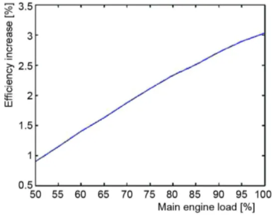
Figure 5 shows greater potential overall efficiency increase of the proposed model at higher main engine loads, greatest being at 100% engine load. This is because of higher scav-enging air pressure at higher main engine loads.
Figure 6 shows the potential of the proposed model with the remark that this effi-ciency data is valid if we compress the scavenge air at the same pressure as in a case without the proposed model. Given results are valid with previously specified assumptions and more detailed calculations, based on experimental data, should be made for more precise results.
Figure 5. Potential overall efficiency increase relative to main engine load for five-stage compression
Figure 6. Efficiency of all three models
Discussion
Although present thermal efficiency is very high relative to the past, we see that there still is room for improvement. Efficiency of systems which include internal combustion engines has reached 55%. Most recent addition to this system, the WHR system which uses exhaust gas energy to produce electricity, has improved the efficiency by approximately 5%. The primal system has three subsystems: main engine, turbocharger, and WHR system. The
principal point of this paper is that the system should be analysed as a whole, and its efficien-cy increase, not only of listed subsystems. If we monitor the air from intake through the fuel combustion to the release of exhaust gases, we can see three processes: compression, combus-tion, and expansion. Compression occurs in two sub-processes: compression in a turbocharger and compression in a compression stroke of the main engine, with intercooling between. Ex-pansion also occurs in two sub-processes: exEx-pansion in an exEx-pansion stroke of the main en-gine and expansion in a turbocharger.
Two-stroke engines need pre-compressed air, so an ideal set of processes would look like this: isothermal compression, adiabatic compression, and combustion and adiabatic expansion. Isothermal compression of air is impossible to perform in reality so we need to be content with the second best, and that is multistage compression with intercooling. The num-ber of stages should be determined on the basis of economic analysis. This paper has given a concept of improvement on that basis and elaborated an analysis of potential efficiency in-crease with previously mentioned assumptions.
The scavenge air pressure is calculated at exact values as available in official data. At main engine load higher than 80%, scavenge air pressure exceeds maximal values, so it must be regulated with a variable exhaust valve opening in main engine. This way work on compression is spent on higher pressures than necessary. This can be avoided by releasing a greater amount of exhaust gases to the WHR system power turbine, thus raising the overall ef-ficiency. A possibility has presented itself with multistage compression and intercooling in a turbocharger, thus giving maximum compression pressure even on partial loads lower than 80%, where a standard turbocharger compresses air to lower pressures than its possible max-imum. Additional tests should be conducted in a laboratory to determine what will be the rise of overall efficiency.
This paper has presented a concept for overall energy efficiency increase in a ships primal power system, proved by some standard thermodynamics equations and calculations, but further study is needed to explore the possibilities of this kind of improvement.
Conclusion
Results of this paper show a potential efficiency increase from 2.2% to 4% for 100% main engine load, relative to number of compression stages. It was also shown that efficiency increase rises with higher main engine load on a five stage compression example. At main en-gine load higher than 80% scavenge air pressure exceeds maximal values so it must be regu-lated with variable exhaust valve opening. But this way work on compression is unnecessarily spent on higher pressures. This can be avoided by releasing greater part of exhaust gases to the WHR system power turbine, raising the overall efficiency. A possibility should be ex-plored, to compress air to its maximum value before a compression stroke intake on main en-gine loads where previous systems have not, to see if system efficiency will rise.
Nomenclature
cp – heat capacity (at constant pressure),
[kJkg–1K–1]
Ef.&o. – fuel and oil energy, [kJkg–1]
nair – polytrophic coefficient of air during compression
p0 – ambient air pressure, [bar]
p1 – air pressure before engine intake, [bar]
T0 – ambient air temperature, [K]
T1 – air temperature before aftercooler and engine intake, [K ]
Tcool – air temperature after intercooler, [K]
Tst.1 – air temperature after first stage of multistage compression, [K]
wcompr_r – real compression work per mass of used turbocharger, [kJkg–1]
Δwcompr – saved work in multistage compressor, [kJkg–1] WHR – waste heat recovery system
z – number of compression stages
multistage compression
ηgen – electric generator efficiency ηincrease – proposed model efficiency rise ηmain_engine – main engine efficiency ηoverall – overall system efficiency ηWHR – waste heat recovery system
efficiency rise
References
[1] Woodyard, D., Pounder’s Marine Diesel Engines and Gas Turbine, 9th ed., Butterworth-Heinemann, Oxford, UK, 2009
[2] Saidur, R., et al., Technologies to Recover Exhaust Heat from Internal Combustion Engines, Renew. Sustain. Energy Rev., 16 (2012), 8, pp. 5649-5659
[3] Aly, S. E., Diesel Engine Waste Heat Power Cycle, Appl. Energy, 29 (1988), 3, pp. 179-189
[4] Shu, G., et al., A Review of Waste Heat Recovery on Two-Stroke IC Engine Abroad Ships, Renew. Sus-tain. Energy Rev., 19 (2013), Mar., pp. 385-401
[5] Medica, V., et al., Performance Simulation of Marine Slow-Speed Diesel Propulsion Engine with Tur-bocharger under Aggravated Conditions, Strojarstvo, 51 (2009), 3, pp. 199-212
[6] Landeka, P., Marine Diesel Engine Cogeneration System, M. Sc. thesis, FESB, Split, Croatia, 2013 [7] ***, MAN B&W, Waste Heat Recovery System (WHRS), http://www.mandieselturbo.com
[8] ***, MAN B&W, 14S90ME-C9.2-TII with 4 x MAN TCA77-26. SMCR: 81,340 kW at 84.0 r/min, http://www.mandieselturbo.com
[9] Dzida, M., Possible Efficiency Increasing of Ship Propulsion and Marine Power Plant with the System Combined of Marine Diesel Engine, Gas Turbine and Steam Turbine, Advances in Gas Turbine Tech-nology, Chapter 3, Gdansk University of TechTech-nology, Gdansk, Poland, 2011