Abstract—Variable speed compressor offers a wider range of
cooling capacity control according to the cooling load of the system. The on/off controller consumes larger energy as the compressor is always working at maximum speed despites the cooling load and continuously on and off to prevent from over cool the room. This study focused on the implementation of variable speed compressor to increase energy efficiency with better temperature control inside the room for split unit air conditioning system. The experiments are done at room temperature of 23 and 24C with internal heat load of 500 and 1000 W. Monitoring system is applied to monitor the room temperature, energy consumption, energy saving and coefficient of performance. The proposed system indicates as much 37% of energy saving as compared to on/off controller.
Index Terms—Residential air conditioning system, split unit,
variable speed compressor, fuzzy logic controller, energy efficiency.
I. INTRODUCTION
HE application of air conditioner (AC) has expanded thorough out the year with variety of applications such as houses, buildings, and hall. The main AC design consideration is providing better thermal comfort at low energy consumption. This in return will make the humans inside the room feel comfortable.
Traditionally, split unit AC system operates at maximum constant speed until it reaches the cooling capacity needed to cool down the room. It operates by turning the compressor on and off continuously until temperature setting is achieved. This causes high energy consumption as
Manuscript received May 20, 2015; revised July 09, 2015. This work was supported by Universiti Teknologi Malaysia: Knowledge Transfer Program (KTP) No. R.J130000.7809.4L509 and Automotive Development Center, Ministry of Education (MOE) Malaysia.
H. Nasution is with Automotive Development Centre, Faculty of Mechanical Engineering, Universiti Teknologi Malaysia, 81310 UTM Johor Bahru, Johor, Malaysia (corresponding author phone: 607-553-5447; fax: 607-553-5811; e-mail: [email protected]).
A. A. Dahlan is with Faculty of Mechanical Engineering, Universiti Teknologi Malaysia, 81310 UTM Johor Bahru, Johor, Malaysia (e-mail: [email protected]).
A. M. Nasib is with Faculty of Mechanical Engineering, Universiti Teknologi Malaysia, 81310 UTM Johor Bahru, Johor, Malaysia (e-mail: [email protected]).
A. A. Aziz is with Automotive Development Centre, Faculty of Mechanical Engineering, Universiti Teknologi Malaysia, 81310 UTM Johor Bahru, Johor, Malaysia (e-mail: [email protected]).
Sumeru is with Department of Refrigeration and Air Conditioning, Politeknik Negeri Bandung Gegerkalong Hilir Ciwaruga Bandung 40012, Indonesia (e-mail: [email protected]).
the current spike during turning on of the compressor. Malaysia commonly uses this type of AC because of the capital cost despite of the high energy consumption used by the AC system [1].
Variable speed drive of the compressor (VSC) implementation is seen as the solution to the problems. VSC continuously varies the compressor speed according to the cooling load which results in less energy consumption and better temperature control [2-4]. The compressor speed is varied by changing the frequency that drives the compressor.
The system operates by converting the fixed frequency of the electrical supply into a variable frequency output. The system’s driver can control the frequency so that the compressor speed operates at the desirable speed by changing to lower frequency to get lower compressor speed and higher frequency to have higher compressor speed. The output can also enabled the variable torque as required by the system so that it matches the amount of energy required to amount of energy needed depending on the workload.
Many types of conventional and intelligent compressor have been studied such as PID [1, 5, 6], rule-based [7] and fuzzy controller [8-12]. PID controller is the most widely used caused by simple design structures at good control system performance and low cost. The VSC load matching capability save much energy at better thermal comfort in AC system using PID controller [13]. Proper selection of proportional (P), integral (I) and derivative (D) gain for the controller has made his experiment get better temperature control and energy saving.
However, the PID controller is very complex to design for a nonlinear system such as a building at open area. Fuzzy logic controller (FLC) offers better control for a nonlinear system such as AC system. The controller can be express in heuristic environment of the occupants in relating thermal comfort [14], thus offering better temperature control. FLC happened to be a popular control method for AC system [8-12, 15].
This study is focused on the development of variable speed compressor for split unit AC system. The FLC controller is implemented to control the compressor speed to obtain energy saving and compared to the on/off controller. The simple installation of the system with higher energy saving is the main advantages of the proposed system. This study is the extension paper from previous work [15].
Indoor Temperature Control and Energy Saving
Potential of Split Unit Air Conditioning System
using Fuzzy Logic Controller
Henry N., Member, IAENG, Afiq A. Dahlan, Affandi M. Nasib, Azhar A. Aziz, Member, IAENG and
Sumeru
T
IAENG International Journal of Computer Science, 43:4, IJCS_43_4_01
(Advance online publication: 26 November 2016)
II. FUZZY LOGIC CONTROL ALGORITHM
Figure 1 show the components involved in designing the FLC controller. The components are input and output variables, fuzzification, inference mechanism, rule base and defuzzification [16]. The input variables is received by the FLC and converted to the fuzzifier. The fuzzy associate memory (FAM) relates the input and output and it is defuzzify for obtaining crisp value [1]. e is the error of
reference and measured temperature while e is the rate of
change of the difference between present error and the previous error. The Z is the output variable which is in this
case is voltage signal to the compressor.
Fig. 1 Split unit AC control structure
µ µ
Δe e
H N C 1 NE NO PO
1
-2 -1 0 1 2 -2 -1 0 1 2
Fig. 2 Membership function of the input variables eand e
µ
ΔZ
SL
3.5
NM FT
1
0 0.5 1 1.5 2 2.5 3 4 4.5 5
Fig. 3 Membership function of the output variable Z
TABLE 1 FUZZY RULE SET
Z H e N C
e
NE SL SL SL
NO SL SL SL
PO FT NM SL
Membership function of e, e and Z is shown in Figure
2 and Figure 3. H (Hot), N (Normal), C (Cold), NE (Negative), NO (Normal), PO (Positive), SL (Slow), NM (Normal), and FT (Fast) represent the fuzzy sets of the controller which is related to the input and output variable. The universe of discourse for e is -2C to 2C, e is -2C to
2C, and Z are 0 to 5 Vdc depending on the thermal
comfort in the room and the voltage for data acquisition range. The triangular method is used for the membership function because it has a good performance [17, 18].
The 3 x 3 rule matrix with 9 rules referring the input and output of the FLC is applied with Mamdani inference
mechanism [15], while the centroid method is applied for defuzzification as it gives stable steady-state result [19] and less complex than other method [20] and works in any situation [16]. The fuzzy rule set is shown in Table 1.
III. AIR CONDITIONING PERFORMANCE
The coefficient of performance (COP) is express for calculating the efficiency of an AC system. The COP can be state by the proportion of heat removal from the evaporator divided by energy required by the compressor or:
) (
) ( COP
1 2
4 1
h h
h h W
Q
com e
(1)
where h1 (kJ/kg) is compressor inlet, h2 (kJ/kg) is
compressor outlet, h4 (kJ/kg) is enthalpy of the evaporator
inlet, Qe (kJ/kg) is the refrigerating effect and Wcom (kJ/kg) is
the work done by the compressor.
Energy consumption by the compressor is the product of power and operation time of the split unit AC system. The equation is:
kWh
t P Energy
kW PF V I
P ( )
1000
(2)
where I is the current (Ampere), V is the voltage while PF is
the power factor. Thus energy saving can be expressed as:
100 AC
Split Existing
AC) Split (FLC -AC) Split (Existing saving
Energy (3)
IV. EXPERIMENTAL SETUP
Figure 4 show the schematic diagram of the split unit AC system on the experimental rig. The temperature and pressure point is shown with the room is insulated. Type T thermocouple and Bourdon pressure gauge is used for measuring temperature and pressure of the AC system respectively. The refrigerant used is R-22 and refrigerant flow meter is placed before the expansion valve. Power meter is used to measure the electric consumption of the AC system.
Fig. 4 Schematic diagram of the experimental rig
IAENG International Journal of Computer Science, 43:4, IJCS_43_4_01
(Advance online publication: 26 November 2016)
The VSC system is consists of LM35DZ temperature sensor inside the insulated room while FLC algorithm is applied into a computer. The inverter used is Optidrive E2 Single Phase Input and Output while the split unit system compressor is 700 W hermetically sealed rotary compressor type. The temperature data logger TC-08 and USB-4716 is used to monitor the data from the AC system. Other data is directly measured with eyes at 5 minutes interval.
The room temperature sensor emitted electrical signal to the controller and computer to analyze the data. The output signal of the error between set temperature and room temperature is generated to vary the compressor speed according to the error. The compressor speed is directly proportional to the frequency of electricity provided to the motor.
A constant speed compressor experiment on the split unit AC system is applied at frequency of 15, 20, 25, 30, 35, 40, 45 and 50 Hz. The split unit is the original unit with thermostat system and retrofitted with VSC controller. The data collected is to analyze the energy consumption, COP and energy saving. The experiments are executed for one hour with temperature setting of 23 and 24C with internal heat load of 500 and 1000 W.
V. RESULTS AND ANALYSIS
A. Constant Speed Performance
The experiments of varying compressor frequency between 15 to 50 Hz have been conducted with various temperature setting and internal heat load. Figure 5 shows the effects of various frequencies of the room temperature and energy consumption at steady state. It can be seen that as the frequency increased, the room temperature is increased and energy consumption is decreased.
Fig. 5 Steady state room temperature and energy consumption at various frequencies
B. Existing System Performance
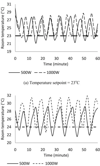
Traditionally AC system is controlled by on/controller or called as thermostat which allowing two conditions of operations either compressor is on or off. The frequency is set at highest that is 50 Hz and as the temperature reaches the temperature setting, the compressor is turned off. The compressor is continuously turned on and off until steady state is achieved. Figure 6 shows the room temperature at various temperature setting and internal heat load.
The main disadvantages of the on/off controller is that the discomfort to occupants inside the room occurred during the temperature is at the upper limit of temperature setting as it
is not accordance to the temperature setting. This is because the thermostat is located inside the evaporator instead of inside the room itself. This type of system is not the best way to control the room temperature that is considered as nonlinear.
Equation (1) is used to calculate COP with average COP of 2.76 at both temperature setting and internal heat load. The COP is zero when the compressor is off.
(a) Temperature setpoint = 23oC
(b) Temperature setpoint = 24oC
Fig. 6 Room temperature responses with thermostat
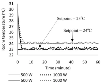
C. Performance of VSC with FLC
Figure 7 shows the room temperature distribution at various temperature setting and internal heat load. FLC is implemented to control the compressor speed according to the error between room temperature and temperature setting. The compressor is run at maximum speed of 50 Hz and decrease as the temperature error between the temperature setting and room temperature is decrease. Moreover, the time taken to cool down the room is faster as the temperature sensor is placed inside the room instead of at the evaporator. After the room temperature is reached, the compressor works at low compressor speed to maintain the room temperature, thus lower energy consumption can be obtained.
0.20 0.30 0.40 0.50 0.60 0.70 0.80
12 17 22 27 32
15 20 25 30 35 40 45 50
Energy
Consumption
(kWh)
Room
Temperature
(
oC)
Frequency (Hz)
Room Temperature (°C) Energy (kWh)
19 21 23 25 27 29 31
0 10 20 30 40 50 60
Room
temperature
(
C)
Time (minute)
500W 1000W
20 22 24 26 28 30 32
0 10 20 30 40 50 60
Room
temperature
(
C)
Time (minute)
500W 1000W
IAENG International Journal of Computer Science, 43:4, IJCS_43_4_01
(Advance online publication: 26 November 2016)
Fig. 7 Room temperature responses with FLC
The average COP for VSC setup is 3.07. Higher COP indicates lower energy consumption of the system. The COP is increased because of lower energy consumption and compressor speed.
D. Energy Analysis
Figure 8 and Figure 9 are the energy consumption and energy saving of the on/off controller compared to FLC system. Different temperature setting and internal heat load does give different results. The results shows that the FLC controller is always have lower energy consumption compared to on/off controller mainly because the lower compressor speed in maintaining the room temperature and no current spikes caused by the on and off behavior of the compressor. Energy saving achieved is between 26 to 37%.
Fig. 8 Energy consumption
Fig. 9 Energy saving
VI. CONCLUSION
An experiment on the split unit AC system with VSC using FLC is done to study the effects on AC performance and energy consumption. The implementation of VSC has
proved that energy saving could be achieved up to 37% depending on the cooling load and temperature setting. The FLC control the speed of the compressor depending on the cooling load thus lower energy consumption can be achieve, increasing energy efficiency of the whole system.
REFERENCES
[1] H. Nasution, “Energy saving of an air conditioning system using PID and fuzzy logic controllers,” Ph.D. thesis, Faculty of Mechanical Engineering, Universiti Teknologi Malysia, Malaysia, 2006. [2] H. Nasution, H. Jamaluddin and J. M. Syeriff, “Energy Analysis for
Air Conditioning System using Fuzzy Logic Controller,” Telkomnika, vol. 9, no. 1, pp. 139-150, April. 2011.
[3] N. Z. Abidin, “Retrofitting of compressor motor in air conditioning systems for energy saving,” M.S. thesis, Faculty of Mechanical Engineering, Universiti Teknologi Malaysia, Malaysia, 1995. [4] Y. C. Park, Y. C. Kim and M. K. Min, “Performance Analysis on a
Multi-Type Inverter Air Conditioner,” Energy Conversion & Management, vol. 42, no. 13, pp. 1607-1621, September. 2001. [5] J. Zhang, G. Qin, B. Xu, H. Hu, and Z. Chen, “Study on Automotive
Air Conditioner Control System Based on Incremental-PID,” Advanced Material Research, vol. 129, pp. 17-22, 2010.
[6] H. Khayyam, A.Z. Kouzani, E. J. Hu and S. Nahavandi, “Coordinated Energy Management of Vehicle Air Conditioning System,” Applied Thermal Engineering, vol. 31, no. 5, pp. 750-764, April. 2011. [7] H. Khayyam, A. Z. Kouzani and E. J. Hu, “Reducing energy
consumption of vehicle air conditioning system by an energy management system,” in Proc. IEEE The 4th International Green Energy Conference, Beijing, China, 2009.
[8] J. M. Sousa, R. Babuska and H. B. Verbruggen, “Fuzzy Predictive Control Applied to Air-Conditioning System,” Control Engineering Practice, vol. 5, no. 10, pp. 1395-1406, October. 1997.
[9] F. Calvino, M. Gennusa, G. Roizzo and G. Scaccianoce, “The Control of Indoor Thermal Comfort Conditions: Introducing a Fuzzy Adaptive Controller,” Energy and Buildings, vol. 36, no. 2, pp. 97-102, February. 2004.
[10] R. Thompson and A. Dexter, “A Fuzzy Decision-Making Approach to Temperature Control in Air-Conditioning Systems,” Control Engineering Practice, vol. 13, no. 6, pp. 689-698, June. 2005. [11] Y. Farzaneh and A. A. Tootoonchi, “Controlling Automobile Thermal
Comfort using Optimized Fuzzy Controller,” Applied Thermal Engineering, vol. 28, no. 14-15, pp. 1906-1917, October. 2008. [12] H. Khayyam, S. Nahavandi, H. Eric, A. Kouzani, A. Chonka, J.
Abawajy, V. Marano and D. Sam, “Intelligent Energy Management Control of Vehicle Air Conditioning via Look-Ahead System,” Applied Thermal Engineering, vol. 31, no. 16, pp. 3147-3160, November. 2011.
[13] H. Nasution and M. N. W. Hassan, “Potential Electricity Savings by Variable Speed Control of Compressor for Air Conditioning Systems,” Clean Technologies and Environmental Policy, vol. 8, pp. 105-111, March. 2006.
[14] L. I. Davis, T. F. Sieja, R. W. Matteson, G. A. Dage and R. Ames, “Fuzzy logic for vehicle climate control, in: Fuzzy Systems,” in Proc. IEEE World Congress on Computational Intelligence, Orlando, USA, 1994, pp. 530-534.
[15] Henry N., Afiq A. Dahlan, Affandi M. Nasib, Azhar A. Aziz, Sumeru, “Performance of a variable speed of the split unit air conditioning system using fuzzy logic controller,” Lecture Notes in Engineering
and Computer Science: Proceedings of the International
MultiConference of Engineers and Computer Scientists 2015, IMECS 2015, 18-20 March, 2015, Hong Kong, pp. 253-257.
[16] K. M. Pasino and S. Yurkovich Fuzzy Control. United State of America: Addison Wesley, 1998.
[17] A. I. Dounis and D. E. Manolakis, “Design of A Fuzzy System for Living Space Thermal Comfort Regulation,” Applied Energy, vol. 69, no. 2, pp. 119-144, June. 2001.
[18] A. Bagis, “Determining Fuzzy Membership Functions With Tabu Search-An Application to Control,” Fuzzy Sets and Systems, vol. 139, no. 1, pp. 209-225, October. 2003.
[19] D. Kolokotsa, D. Tsiavos, G. S. Stavrakakis, K. Kalaitzakis and E. Antonidakis, “Advanced Fuzzy Logic Controllers Design and Evaluation for Buildings’ Occupants Thermal Visual Comfort and Indoor Air Quality Satisfaction,” Energy and Buildings, vol. 33, no. 6, pp. 531-543, July. 2001.
[20] I. Eker and Y.Torun, “Fuzzy Logic Control to be Conventional Method,” Energy Conversion & Management, vol. 47, no. 4, pp. 377-394, March. 2006.
22 23 24 25 26 27 28 29 30 31
0 10 20 30 40 50 60
Room
temperature
(
oC)
Time (minute)
500 W 1000 W
500 W 1000 W
Setpoint = 23oC
Setpoint = 24oC