Shape Memory Alloy Actuator forBio-medical application
Prashin Sharma
MSc (Mechanical Engineering), Managing Director at Hindustan Security Force, India
Past Graduate StudentDepartment of Mechanical engineering,Carnegie Mellon University, PA – 15213
Abstract
In this paper various applications of shape memory alloys (SMA) in bio-medical field based upon their material properties are discussed, and a novel SMA spring actuator design for biopsy is proposed. Design parameters such as spring configuration, wire diameter required for designing the actuator were defined and obtained through experiments. Finally, itconcludeswith the possibility of using SMA spring for high force compact system.
Keywords
: Shape memory alloy, biopsy, bio-medical, actuatorI.
INTRODUCTION
Shape Memory Alloys have been at the forefront of research for the past decade. They are becoming an integral part of design of a variety of new medical products. A few common examples of shape memory alloys are Nickel-titanium, Copper-aluminum-nickel,Copper-zinc-aluminum etc. Shape memory alloys are a unique class of shape memory materials.
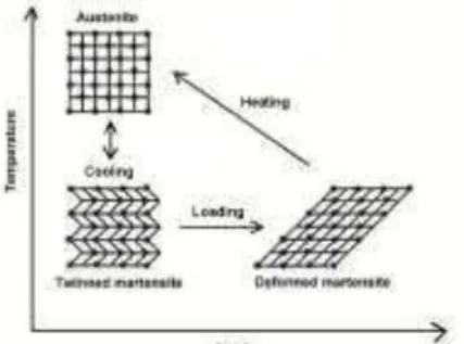
SMAs are metallic alloys that have the ability to „remember‟ and return to their predetermined shape when heated which involves the rearrangement of particles within the crystal structure of the solid. An increase in temperature can result in shape recovery even under high applied loads therefore resulting in high actuation energy densities. As illustrated in the stress- temperature graph fig 1, Ms and Mf designate the martensite start and finish temperatures respectively, while As and Af represent the austenite start and finish temperatures respectively. Upon cooling in the absence of applied load the crystal structure changes from austenite to martensite. The phase transition from austenite to martensite is termed as forward transformation. The arrangement of variants occur
Fig 1. GeneralTemperature vs strain diagram of shape memory alloy
such that macroscopic shape change is negligible. The phase transition from austenite to martensite is termed as forward transformation. When the material
is heated from martensitic phase it slowly transforms into the austenite phase [As] and this transition is called as reverse transition during which there is no associated phase change. If a mechanical load is applied the material in twinned martensitic phase (at low temperature), it is possible to detwin the martensite by reorienting a certain number of variants resulting in macroscopic shape change. A subsequent heating of the SMA to a temperature above Afwill result in reverse phase transformation (from detwinned martensite to austenite) and will lead to complete shape recovery. Cooling back to temperature below Mf (forward transformation) leads to formation of twinned martensite again with no associated shape change observed.
II.
SMA PROPERTIES
The unique property of shape recovery of shape memory alloys is possible due to the solid state phase transformation between the low temperature martensite[M] phase and the high temperature austenite[A] phase and they only differ in their crystallographic structure. This ability is known as shape memory effect.
Fig 2. Different phases of shape memory alloys
There are two types of shape memory effect.
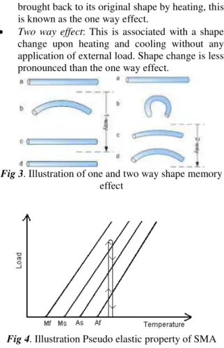
One way effect: When the SMA is deformed within its pseudoplastic strain range and then
brought back to its original shape by heating, this is known as the one way effect.
Two way effect: This is associated with a shape change upon heating and cooling without any application of external load. Shape change is less pronounced than the one way effect.
Fig 3. Illustration of one and two way shape memory effect
Fig 4. Illustration Pseudo elastic property of SMA
Pseudo elasticity is another unique property of shape memory alloys. It occurs when in the austenite phase, it is possible for the SMA to undergo a phase change at a constant temperature. This is achieved by increasing the load acting on the SMA while at a constant temperature greater than Af, and as illustrated in the graph, the phase change into martensite takes place.
III.
SMA APPLICATIONS
Nitinol is being used in the military, medical, safety, and robotics applications. Many of the current applications of Nitinol have been in the field of medicine.
Fig 5. Illustration of forceps
Anchors with Nitinol hooks are used to attach tendons to bone. An orthodontic wire made out of
Nitinol reduces the need to retighten and adjust the wire. These wires also accelerate tooth motion as they revert to their original shapes. Nitinol eyeglass frames can be bent totally out of shape and return to their parent shape upon warming. Nitinol needle wire localizers are used to locate and mark breast tumors so that subsequent surgery can be more exact and less invasive, utilizing the metal's shape memory property. Nitinol is also used for guiding catheter.
One of the interesting applications of SMA is in the atrial septal-defect occlusion system (ASDOS) (OsypkaMedizintechnik, Rheinfelden, Germany). This device is the first to allow nonsurgical repairs of occlusions, or holes, in the atrial wall of the heart. The actual device comprises two small umbrellas consisting of five nitinol wire loops supporting webs of microporous polyurethane (see fig 6). The two umbrellas are passed into the body while folded into two catheters, and are positioned one each on either side of the defect area. A guidewire passing directly through the hole is used to ensure that the two catheters and umbrella devices are positioned correctly. Once positioned, the umbrellas are pushed forward from their catheters and screwed together using a special torquing catheter. The resulting sandwich forms a patch, occluding the atrial defect. Available umbrella diameters range from 20 to 65 mm. [1]
Fig 6.The atrial septal-defect occlusion device is used to seal holes in the heart wall.
The extraordinary compliance of nitinol clearly makes it the metal that is most similar mechanically to biological materials. This improved physiological similarity promotes bones ingrowth and proper healing by sharing loads with the surrounding tissue, and has led to applications such as hip implants, bone spacers (see fig 7), bone staples, and skull plates.
Fig 7. Spinal vertebrae spacer shown in the martensitic state (left) and deployed superelastic state
The most celebrated super elastic application of shape memory alloys in medical devices are self-expanding stents, used to brace the inside circumference of a tubular passage such as an esophagus, bile duct, or blood vessel (see fig 8). Probably the most interesting area of application is in the cardiovascular system, as a follow-up to balloon angioplasty. The placement of a stent has been shown to significantly decrease the propensity for restenosis. Like the vena cava filter, these devices are generally permanent implants, deployed through a catheter using the shape-memory effect.
Fig 8. Stents made from nitinol tubing
Advantages
Bio-compatibility
Diverse fields of application
Good mechanical properties
Disadvantages
Expensive to manufacture
Poor fatigue properties
Hysteresis
IV.
BIOPSY FORCEPS
Biopsy forceps (fig. 5) is a device commonly used for tissue sampling during esophagostroduodenoscopy which is a diagnosticendoscopic procedure that visualizes the upper part of the gastrointestinal tract up to the duodenum. It is considered a minimally invasive procedure since it does not require an incision into one of the major body cavities and does not require any significant recovery after the procedure (unless sedation or anesthesia has been used). The advantages of using forceps is its small size which causes less discomfort to the patients, also multiple tissue samples can be collected during single operation. A test rig was designed to simulate the motion of the forceps while performing biopsy and measure the forces applied by the operator. Force required for cutting the tissue sample is an important parameter for designing the SMA actuator.
A. Test Rig Design
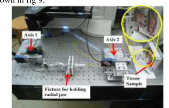
Tomeasure the forces required while performing biopsy a test rig was designed with two degrees of freedom or two axis.Axis 1 was used to control opening and closing of the forceps and axis 2 was used for tearing the biopsy sample out of the tissue
when the jaws of the forceps was fully closed as shown in fig 9.
Fig9. Test rig to measure the forces for performing biopsy using forceps
Forceps which was used in this experiment is Radial Jaw3 manufactured by Boston Scientific. Two linear stages MFA CC Linear Miniature Series made by Newport were used for actuating the two axes. The maximum linear speed attainable by the linear stages was 3mm/s. To measure the forces applied two load cells, MLP10 product of Transducer technology, were used, one with each axis placed coaxially along the axis of applied force. Pig esophagus was used as the tissue sample for performing the biopsy.
B. Results
The linear stages were operated at their maximum linear speed while performing the experiment. The forceps was fully open when it was pressed against the tissue sample, also the full area of the forceps was in contact with the tissue sample before closing the forceps. Successful biopsy wasobtained and results are illustrated in the graph.
Fig10. Forces measured from axis 1 while performing biopsy
Fig 11.Forces measured from axis 2 while performing biopsy
V.
ACTUATOR DESIGN
We will be designing an actuator using SMA to actuate the axis 1, which is used for opening and closing the radial jaw or forceps for performing biopsy.
A. Design Parameters
From the experiment conducted, application and published papers [2] various parameters for design of the actuator were identified. They are as follows: i) Tip velocity of the forceps, whichaffects the
local effective modulus (LEM) of the tissue. LEM provides quantitative estimate of the tissue deformation resistance immediatelypreceding the extension of the cut [3].
ii) Force required to be generated by the actuator. iii) Since forceps are used for minimal invasive
surgery, the actuator should be as compact as possible to reduce the discomfort to the patient. iv) The actuator should be bio-compatible. v) Power requirements of the actuator.
B. Actuator Design
Based on the parameters defined above, a novel actuator was conceptualized which could provide the required forces and velocity for performing biopsy.
Fig 12. Actuator concept
The actuator uses SMA spring and a steel spring. SMA 1 which is attached to a ferromagnetic material is used as a latch. The steel spring is attached to a magnet as shown in fig.12 which is denoted by M. SMA 2 is placed in parallel configuration to the steel spring to dampen the vibrations along with providing some force when closing the forceps. Magnet M is connected to the 5 bar mechanism through a rigid link. 5 bar linkage mechanism is used to transmit
forces and motion in opposite direction of that of the magnet, to the forceps. Thus when magnet moves to the right the forceps closes and when magnet moves to the left the forces opens. The basic principle of actuator is that, electric energy provided to the shape memory alloy spring is stored as potential energy (PE) in the steel spring until the point when the spring force is greater than magnetic attractive force acting between the ferromagnetic material and magnet. The stored PE of the steel spring is used to actuate the forceps.
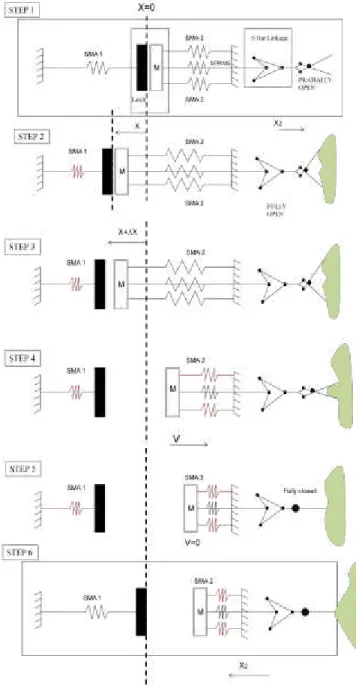
Fig 13. Steps involved in actuation
SMA 1 is actuated by passing current through it as shown in Step 1. Since SMA 1 and steel spring are coupled my magnetic attractive force acting between the ferromagnetic material and magnet, thus resulting in deflection of spring as SMA 1 contracts due to
electrical heating. In this step the forceps open and pushed against tissue. SMA 1 continues to contract until the magnet detaches from the ferromagnetic material as shown in Step 3. As the magnet M moves toward right SMA 2 is actuated so that it provides added force to spring force to the link connected to 5 bar linkage mechanism, also to dampen the vibrations of spring. As a result the forceps tends to close biting the tissue sample. At the end of step 5 the forceps is completely closed having the biopsy sample inside it. Current supplied to SMA 1 is stopped and the forceps is pulled out to tear the sample still attached to tissue. In step 7 current supplied to SMA 2 is also stopped and the actuator returns back to its original position as shown in step 1.
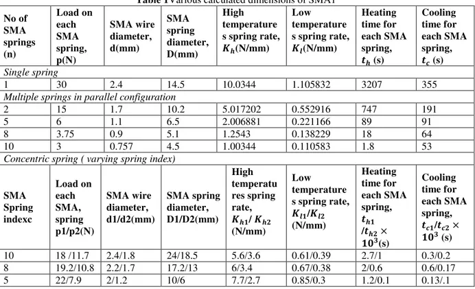
Table 1Various calculated dimensions of SMA1
No of SMA springs (n) Load on each SMA spring, p(N) SMA wire diameter, d(mm) SMA spring diameter, D(mm) High temperature s spring rate, ��(N/mm)
Low temperature s spring rate, ��(N/mm)
Heating time for each SMA spring, �� (s)
Cooling time for each SMA spring, �� (s)
Single spring
1 30 2.4 14.5 10.0344 1.105832 3207 355
Multiple springs in parallel configuration
2 15 1.7 10.2 5.017202 0.552916 747 191 5 6 1.1 6.5 2.006881 0.221166 89 91 8 3.75 0.9 5.1 1.2543 0.138229 18 64 10 3 0.757 4.5 1.00344 0.110583 1.8 53
Concentric spring ( varying spring index)
SMA Spring indexc Load on each SMA, spring p1/p2(N) SMA wire diameter, d1/d2(mm) SMA spring diameter, D1/D2(mm) High temperatu res spring rate, �� / �� (N/mm) Low temperature s spring rate, �� /�� (N/mm) Heating time for each SMA spring, �� /�� × (s) Cooling time for each SMA spring, �� /�� × (s)
10 18 /11.7 2.4/1.8 24/18.5 5.6/3.6 0.61/0.39 2.7/1 0.3/0.2 8 19.2/10.8 2.2/1.7 17.2/13 6/3.4 0.67/0.38 2/0.6 0.6/0.17 5 22/7.9 2/1.2 10/6 7.7/2.7 0.85/0.3 1.2/0.1 0.13/.1
C. Design Calculations
We have designed SMA 1 spring which is one of the most important component of the whole system. Various assumptions were taken into considerations while design calculations of shape memory alloy spring. The maximum force which acts on SMA 1 is in step 3 just before magnet and the ferromagnetic material detach. This design force is assumed to be around 30 N which is required to cut the tissue. SMA spring is designed in the linear region of the stress strain curve. The heating and cooling time constant calculated for the shape memory alloy spring was based on still air conditions. Also the temperature inside the human body was considered to around 37℃. The high and low temperature shear modulus
multiple springs in parallel configuration different wire diameters were obtained for each spring.
(a) (b)
Fig 14. (a) Single spring configuration, (b) concentric spring configuration
The actuator size is constrained to a cylinder with dimensions of 10 mm radius and 30mm length. The spring index chosen for design of single and multiple spring configuration is 6.The diameter of the SMA spring is defined by the following formula,
= 8� ��
Where,
d= diameter of the wire (mm), p= load applied (N), c= spring index,� = shear stress.
No. of turns for the spring is defined by,
= × /(�× 2×� )
Where,
� = shear strain associated with stroke Stroke length required is 5mm
The high temperature and low temperature spring rates are defined by the following formulae respectively,
High Temperature stiffness,
= 4 8 3
Low Temperature stiffness,
= 4 8 3
Where,
= High temperature shear modulus, = Low temperature shear modulus, n = number of turns
Since still air condition operation were assumed the heating time constant is assumed as follows,
= 12.06 + 8011.3 × 2
�� = 0.645 × + 6.18 × 10⁻³ 2
2 Where,
I = current in amp,
��= maximum temperature where the rate of heat generated by the current is equal to the rate of heat loss by convection.
The time required for heating the wire is given by the formula,
ℎ = �� − �
�� − � + 5.064
× 107 4
2
�� − �
�� − � The cooling time constant is assumed as follows,
= 13.256 + 12068.6 × 2
And time required for the SMA to cool down is given by the formula
�� = ��−− �
� +
28.88 − � Where,
= Martensites finish temperature.
For concentric SMA spring design the load distribution on each spring is directly proportional to the wire diameter, thus the ratio yields the following relationship,
�1 �2
= 1
2 2
And the diameter of the wire are related through the following relation which is a function of spring index.
1
2 =
−2
D. Results
Based on the above mentioned formulae Table 1 was created for different configurations. It could be inferred from the table that for single SMA spring configuration the wire diameter is 2.4mm and average diameter of the spring is 14.5 mm which more than constraints hence it is ruled out. As we go for multiple springs in parallel configuration though the heating and cooling time of each spring decreases, it requires a larger area to be installed. For the concentric spring as the spring index in decreased till c=5, SMA spring dimensions are within the dimensional constraints. But the heating and cooling time are quite high.
VI.
CONCLUSION
ACKNOWLEDGEMENTS
I would like to thank
Prof. MetinSitti (CMU) who provided insight and expertise that greatly assisted during the course of this research. I, would also like to thank Paul Glass (CMU, PhD. Candidate) for assisting with lab set up for performing experiments.REFERENCES
[1] www.devicelink.com
[2] “Mobile in Vivo biopsy robot“, Mark E.Rentscheler, Jason Dumpert, Stephen R. Platt, Dmitry Oleynikov, Karl Iagnemma, 2006 IEEE ICRA.
[3] “Development of a Surgical Simulator for Laparoscopic Esophageal Procedures”, Changmok Choi, Hyonyung Han, Bummo An, and Jung Kim, Proceedings of the 28th IEEE, EMBS Annual International Conference
[4] “Modeling Soft-Tissue Deformation Prior to Cutting for Surgical Simulation: Finite Element Analysis and Study of Cutting Parameters “, TeeranootChanthasopeephan, Student Member, IEEE, Jaydev P. Desai*, Member, IEEE, and Alan C. W. Lau, IEEE Transactions on Biomedical Engineering, Vol. 54, No. 3, March 2007
[5] Actuator design using shape memory alloys by Tom Waram