Effects of centrifugal and Coriolis
forces on the mold-fi lling behavior of
titanium melts in vertically rotating
molds
*Xu Daming, Jia Limin and Fu Hengzhi
(Institute of Solidifi cation Processing of Materials, School of Materials Science and Engineering, Harbin Institute of Technology,
Harbin 150001, Heilongjiang, P. R. China )
Abstract: The vertical centrifugal-casting technique is widely used in the manufacture of various irregularly-shaped castings of advanced structural alloys with thin walls, complex shapes and/or large sizes. These castings are used in the increasing applications in aero-space/aviation industries, human teeth/bone repairs with near-net shaped components, etc. In a vertically rotating casting system, the mold-filling processes of alloy melts, coupled with solidifi cation-heat transfer, may be much more complicated, because they are driven simultaneously by gravity, centrifugal and Coriolis forces. In the present work, an N-S/VOF-equations-based model, solved using a SOLA-VOF algorithm, under a rotating coordinate system was applied to numerically investigate the impacts of centrifugal and Coriolis forces on metallic melt mold-fi lling processes in different vertical centrifugal-casting configurations with different mold-rotation rates using an authors’ computer-codes system. The computational results show that the Coriolis force may cause remarkable variations in the fl ow patterns in the casting-part-cavities of a large horizontal-section area and directly connected to the sprue via a short ingate in a vertical centrifugal-casting process. A “turn-back” mold-filling technique, which only takes advantage of the centrifugal force in a transient rotating melt system, has been confi rmed to be a rational centrifugal-casting process in order to achieve smooth and layer-by-layer casting-cavities-fi lling control. The simulated mold-fi lling processes of Ti-6Al-4V alloy melt, in a vertical centrifugal-casting system with horizontally-connected plate-casting cavities, show reasonable agreement with experimental results from the literature.
Key words: centrifugal casting; Coriolis force; mold-fi lling; solidifi cation-heat transfer; computer simulation CLC number: TG146.2+
3 Document code: A Article ID: 1672-6421(2008)04-0249-09
T
he conventional centrifugal-casting technique was mostly used to produce cylinder-like castings of various diameters and various alloys since the 40s of the last century [1,2]. To makethese symmetrical castings, both horizontally and vertically rotating molds can be adopted, depending on the length-to-diameter ratios of the castings. However, with increasing special applications of advanced structural alloys, e.g. titanium-based alloys in aero-space / aviation industries etc., the vertical centrifugal-casting technique is now widely used in the manufacture of various irregularly-shaped castings with thin walls and/or large sizes with high quality [2-9].
Compared with a gravity casting process, more complicated centrifugal-mold-filling behavior of alloy melts, caused by the complex driving forces, will be presented in a vertical
Male, born in 1958, professor. Directions of research: theory of materials solidifi cation and structure control; computer modeling of solidifi cation transport phenomena and casting technological CAD.
E-mail: [email protected]
Received: 2008-06-28; Accepted: 2008-09-06
*Xu Daming
centrifugal-casting process. Due to the mold rotation and the opacity of both the metallic melts and the mold materials,
such complicated mold-fi lling and the coupled heat-transfer/ solidifi cation behavior is diffi cult to determine experimentally.
Therefore, much research effort has been devoted to developing a numerical simulation technique and computer codes as a tool [8-16] for achieving a rational technological
control for a centrifugal-casting process.
It is well known that in a rotating system, a mass moving/
fl owing radially away from the axis of rotation will receive an
additional force, termed a Coriolis force [17]. This force may
cause different mold-fi lling behavior in a vertical
centrifugal-casting process, as revealed by hydraulic simulations [18]. In
that the Coriolis force may exert a less important influence in some cases. Therefore, this article aims at investigating
the infl uences of both the centrifugal and Coriolis forces on
the mold-filling and the coupled heat-transfer behavior in an application-oriented vertical centrifugal-casting system, using general 3D-simulation purpose codes developed by the authors. Extensive computations are involved in the present numerical investigations on different vertical
centrifugal-casting confi gurations with different mold-rotating rates.
1 Computational model
The configuration of the vertical centrifugal-casting system and the coordinate systems used are illustrated in Fig. 1 for the present modeling description. In the schematics, the
dot-dot-dash lines defi ne a mold-cavity into which the alloy melt
is poured with an inlet velocity, Vo, and an initial temperature,
TP. The melt is allowed to flow freely and occupy the
confined space. The mold, of different material(s) and at an initial temperature much lower than TP, is not shown in the
schematics for simplicity. In this simple centrifugal-casting system, two horizontal square plate-castings are symmetrically attached to the root of the vertical sprue via a short runner.
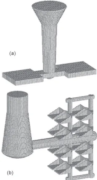
Fig. 2 Mesh patterns made in the present
centrifugal-mold-fi lling simulations: (a) for experimental vericentrifugal-mold-fi cation;
(b) for an application-oriented modeling.
In the mold-fi lling and solidifi cation processes, the casting
mold system is made to rotate horizontally around the vertical axis of the sprue at a constant angular rate, ωo, relative to the
(static) laboratory coordinate system, x'-y'-z'. A rotating linear
coordinate system, x-y-z, is chosen fi xed to the turning mold
system with the central axis of the sprue as the z-axis, see Fig. 1. For the application-oriented centrifugal-casting system shown in Fig. 2(b), a similar rotating coordinate system, x-y-z, is
Fig. 1 Schematic vertical centrifugal-casting confi guration
and the coordinate systems
The governing equations for the centrifugal mold-filling and the coupled heat-transfer processes of an alloy melt are derived based on a control volume (CV) A, which is taken from the filling melt domain under the constantly rotating coordinate system, x-y-z, as shown in Fig. 1. Therefore, with the assumption of constant alloy properties, the mathematic model for the present numerical investigations may take the following formulation form:
Volume of fl uid (VOF) equation
(1) Momentum transfer equation
(2) Continuity equation
(3) Heat energy transfer equation
In the present model, the vector symbol, v = vxi + vyj +
vzk, represents a melt-flow velocity relative to the rotating
coordinate, x-y-z, system. The variable F in volume of fl uid (VOF) Eq. (1) represents the volume fraction of fl owing melt
that occupies the CV concerned. VOF technique is typically employed to define and track the free surface of the mold-filling melt for a casting process [19], and is also adopted in the present numerical modeling for the centrifugal casting processes; t is the symbol for time. This modeling equation in fact forms an important part of the Mixed Interface-Tracking/ Interface-Capturing Technique (MITICT), which has been
more recently proposed and successfully applied to the fi nite
element computations of flow problems by Akin, Tezduyar et al. [10-12]. In Eq. (4), T and fS represent temperature and the
volume solidified phase fraction, respectively; a represents thermal diffusion coefficient, a = m/cPtL, in which m and tL
represent heat conductivity and density of fl uid, respectively; h
and cP represent the latent heat and specifi c heat, respectively.
In the momentum transfer equation, Eq. (2), a Navier-Stokes equation with more external body-forces, the fourth term on the right-hand-side, an = ωn²rA, represents the centrifugal
acceleration, where rA is the vector distance from the axis of
rotation pointing to the mass-center of the concerned control melt-volume A, as shown in Fig. 1. g is the gravity vector and P represents pressure; c is the kinetic viscosity of fl uid.
The absolute angular velocity of the A-CV, ωn, i.e. in the
lab-coordinate x'-y'-z', can be expressed as: [10-12]
(5) Where, i is the angle between the x-axis and the projection of the vector rA on the x-o-y plane. The last term on the
right-hand-side of Eq. (2) represents the Coriolis acceleration [17],
which can be viewed as a kind of inertia force.
SOLA-VOF algorithm [20, 21] is widely used in various
casting-CAE computer codes for casting mold-filling computations. In the present work, this numerical solution technique is also employed to calculate the centrifugal mold-filling procedures (VOF-distribution), the relative velocity field, etc., but in a rotating coordinate system, based on the heat-transfer-coupled mathematical model of Eqs. (1) – (5)
and a centrifugal casting confi guration as illustrated by Fig. 1.
All the numerical computations are performed with authors-developed software, 3DLX-WSIM, for a general
3D-simulation purpose for various casting processes both only under gravity (setting ωo = 0) and in a rotating casting-mold
system. The codes system consists of three main modules of pre-processing, numerical computation, and post-processing. The pre-/post-processing modules provide basic functions of 3D geometrical construction and meshing for a casting system, and 3D color-image presentations for the calculated results
of different centrifugal mold-fi lling and coupled heat-transfer
processes. All the computations by the simulation module and the color-image presentations by the pre-/post-processing modules can be performed on a PC-computer.
Two vertical centrifugal-casting confi gurations are designed
for the present numerical investigations. The corresponding CV-meshed casting systems are shown in Fig. 2, which is an image output of the present computer codes. The first casting configuration, shown by Fig. 2(a), is primarily for the numerical model validation with centrifugal-casting experiments of Ti-6Al-4V melt quoted from the literature [22]. In the experiments of Suzuki et al.[22] two square plates of dimensions: 80 mm × 80 mm × 10 mm were cast using the vertical centrifugal-casting technique as depicted in Fig. 1. The entire cavity of the casting system, with maximum turning radius of ~ 120 mm, is meshed into 66924 cubic CVs of size 2 mm, Fig. 2(a). The second vertical centrifugal-casting system, shown in Fig. 2(b), is for an application-oriented
confi guration for multiple thin-wall Ti-6Al-4V castings, which
is constructed with 144188 cubic CVs and with maximum turning radius of ~ 650 mm. This meshing model will be used for the numerical investigations of the centrifugal/Coriolis effects on a complicated casting system.
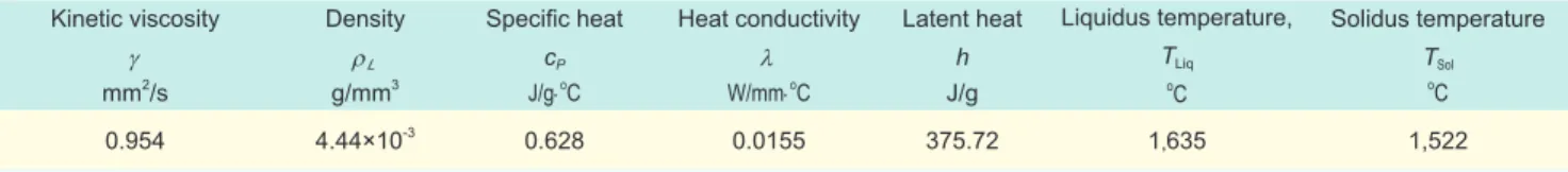
The properties data used for the model casting alloy of Ti-6Al-4V for the present computations are listed in Table 1. For the computation group of plate-castings of Fig. 2(a), for both numerical investigation and experimental verification, a temperature-dependent viscosity, expressed by Eq. (6), is employed instead of the constant viscosity.
For the present computations, the critical temperature, TCritic, is
taken as TCritic = TLiq – 0.55(TLiq – TSol), below which the solidifying
solid dendrites will form a rigid packed matrix blocking the
bulk-fl ow of the alloy melt, where TLiq and TSol represent the
liquidus and solidus temperatures of the investigated alloy, respectively.
Table 1 The properties data used in the present computer simulations for Ti-6Al-4V alloy
Kinetic viscosity γ mm2/s
Density ρL g/mm3
Specifi c heat
cP J/g⋅o C
Heat conductivity λ W/mm⋅o
C Latent heat h J/g Liquidus temperature, TLiq o C Solidus temperature TSol o C
0.954 4.44×10⁻³ 0.628 0.0155 375.72 1,635 1,522
2 Experimental validation of model
According to the mathematic defi nition for the Coriolis force
vector, -2ωo ×v, the Coriolis force directions in a vertical
centrifugal casting system will be confined in a rotating
plane, i.e. horizontally, and are normal to the fl ow directions
of the melt CV concerned. Therefore, the centrifugal casting
confi guration for horizontal plate-castings, shown by Fig. 2(a),
is suitable for investigating the impact of both the Coriolis
and centrifugal forces on the casting-cavity fi lling behavior of
alloy melts. The pouring velocity and the initial temperature of the Ti-6Al-4V melt are set to be Vo = -280 mm/s and TP =
1,700 ℃, respectively, for the numerical simulations performed in this section.
A comparison between the calculated centrifugal-mold-filling behaviors in plate-casting cavities at a mold-rotation rate of 60 rpm with and without Coriolis-force considerations is shown by Fig. 3 in a VOF-display mode. The computational results of Figs. 3(a) to 3(c) are obtained using the full model of Eqs. (1) – (5), while the result of Fig. 3(d) is the output using a reduced mathematical model in which the Coriolis force term in the momentum transfer Eq. (2) was disabled. Figs. 3(a) and 3(b) give an outside view and a horizontal section view,
respectively, for an early casting-cavity-fi lling behavior with
clockwise (negative) mold-rotating direction. It can be seen that in this case, the horizontally spreading alloy melt, from the vertical pouring, flows towards the aproaching sides of the clockwise-turning plates-mold cavities, and then turns its
fl owing directions when touching the sidewalls of the
mold-cavities, Fig. 3(b).
For the case of counter-clockwise (positive) mold-turning,
the melt fl ow pattern in the casting cavities is closely similar
to that of clockwise-rotating case, but towards the opposite sidewalls of the casting cavities as expected, because the Coriolis force is also rotation-direction dependent. Such a result is shown in Fig. 3(c). In both cases of Fig. 3(a)/3(b) and Fig. 3(c), the casting-cavities filling melts are also simultaneously driven by the centrifugal forces, whose directions are always away from the rotating axis. This phenomenon can be easily seen from Fig. 3(d), in which the Coriolis force was removed.
The simulation results comparison of Fig. 3 also shows that,
the casting-cavity-fi lling pattern of the alloy melt in a vertical
centrifugal-casting system may vary dramatically under a Coriolis-effect, if the casting-cavities of a large horizontal-section area are directly connected to the vertical sprue via a short ingate. Furthermore, the present full-model simulation
results indicate that the direct mold-fi lling processes shown in
Figs. 3(a) to 3(c) are not good for obtaining a sound casting, because with the further mold-filling proceeding, some gas holes, evolved from the melt-mold interface reactions, may be
easily engulfed by the fi lling alloy melt. This casting-defect
has been revealed by a similar titanium centrifugal-casting experiment carried out by Suzuki et al [22].
In the experimental work of Suzuki et al. [22], the authors employed a partial mold-filling technique to investigate the
behavior of casting-cavity fi lling and gas hole entrapment with
different mold-rotation rates from 100 to 400 rpm. Figure 4 gives a comparison between the present computational results (a) & (c) and Suzuki’s experimental observations on 20 %
partially-fi lled Ti-6Al-4V plate-castings at a mold-rotation rate
of 200 rpm. Because the optical appearance of the partially-filled casting-parts, shown by Fig. 4(b) (i.e. Fig. 2(b) in reference [22]), was taken after the centrifugal-mold-filling experiment completed, only the shell part, resulted from the
touch of the fi lling melt with the cold mold-walls, is available for comparison of the fl ow pass at that fi lling stage. The X-ray
photographs, shown by Fig. 4(d) (Fig. 3 of reference [22]), taken for the left side of that shown in Fig. 4(b) represents the
fi nal solidifi ed part under a steady rotating condition of 200
rpm, and can be used for comparison with steady melt VOF-pattern that partially filled in the constantly rotating casting mold. From Fig. 4, a reasonable agreement between the computational results and the quoted experiments can be seen.
3 Infl uences of mold-rotating velocities
The vertical centrifugal-casting system to be simulated in Fig. 3 Comparison between the calculated
centrifugal-mold-fi lling behaviors in the plate-casting cavities,
shown by Fig. 2(a), at a rotation-rate of -60 or 60 rpm with and without Coriolis-force considerations (an outside or horizontal section view for an early
casting-cavity-fi lling stage): (a), (b) and (c) using the
Fig. 4 Comparisons between simulation results (a) & (c) and quoted experimental observations (b) & (d)[22] for
centrifugally cast horizontal plates of Ti-6Al-4V (20 % partially-fi lled) with a mold rotation-rate of 200 rpm: (a) and (c) show the simulation results for a plate-fi lling stage and fi nal solidifi cation stage, respectively; (b)
and (d) give optical and X-ray photographs, respectively. gating system, consisting of a rotating inlet-melt container (a
special sprue), a horizontal runner and a vertical gating frame. 16 dustpan-like castings are attached to the vertical gating frame via a short in-gate in four columns and four layers. In this application-oriented configuration [23], a “turn-back” mold-filling technique is employed, which has been shown to be rational to ensure the casting’s quality with a vertical centrifugal casting process [4, 16, 24]. The pouring temperature and the downward inlet-velocity of the alloy melt are assumed to be 1,700 ℃ and Vo = -1,000 mm/s, respectively, for the
numerical investigations in this section.
During a centrifugal casting process, the casting mold is assumed to turn around the z-axis, which superposes with that of the downwards inlet-melt with a round section, at a
constant angular velocity, ωo. Effects of both the different
magnitudes and directions of the mold-rotating velocity ωo
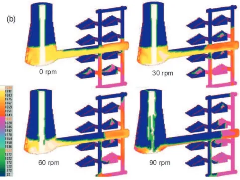
on the centrifugal mold-filling behavior will be tested in this computation section. All the 3D image-presentations in this section are output from the 3DLX-WSIM system in a VOF/temperature-composite-display mode. The different
colors in the fi lling melt domains represent the corresponding
temperatures of the alloy melts, as defined by the color-temperature (C-T) scale shown in each figure of the computational results.
To investigate the influences of the centrifugal force and Coriolis force on the mold-filling behavior separately, the Coriolis force term in Eq. (2) is again temporally removed for
the following fi rst computational series of Figs. 5 and 6.
Figure 5 shows two comparison g r o u p s f o r t h e s i m u l a t e d
centrifugal-mold-fi lling behavior at
different mold-rotating velocities using the reduced model without Coriolis-effect consideration for an initial and an early casting-cavity-filling stage, respectively. From these calculated results, in a centrally-longitudinal-section view, it can be seen that under a mold-rotating condition the filled alloy melt, which possesses a stronger mold-filling ability compared to the gravity-casting case (i.e. zero m o l d - t u r n i n g v e l o c i t y , ωo = 0
Fig. 5 Comparisons among the simulated centrifugal-mold-fi lling behavior
(a centrally-longitudinal-section view) in the Fig. 2(b)-shown mold-cavity of different rotation-rates using a model without Coriolis-force consideration:
at an initial mold-fi lling stage (a); at an early casting-cavity-fi lling stage (b)
Figure 6 gives an outside view and a horizontal-section v i e w t h r o u g h t h e a x i s o f t h e h o r i z o n t a l r u n n e r f o r the same simulated mold-filling behavior as shown i n F i g . 5 ( b ) f o r t h e c a s e s with mold-rotation rates of 30 rpm and 60 rpm. These f i g u r e s m a y o f f e r m o r e information confirming that, under the assumed condition of no Coriolis force being
present, the fi lling melt in the
horizontal runner will touch t h e l o w e r s i d e o f r u n n e r -cavity due to gravity.
Fig. 6 An outside view (upper row) and a horizontal-section view (lower row) for the
simulated centrifugal mold-fi lling behavior at the same mold-fi lling stage as shown
by Fig. 5(b) for the cases with mold-rotation rates of 30 rpm and 60 rpm (without Coriolis-force consideration)
Q u i t e d i f f e r e n t f i l l i n g -behavior in this cavity-part w i l l b e s e e n b e l o w w h e n using a full model with the
all with approximately the same fi lled melt-volume as that of
Figs. 5(b) and 6, are shown in Fig. 7. These computational results are obtained using the full model of Eqs. (1) to (5), in which all the driving forces from the gravity, centrifugal and Coriolis accelerations have been taken into account. Again it
can be seen that the mold-fi lling abilities of the alloy melt can be signifi cantly enhanced in a centrifugal casting process.
Furthermore, by comparing each case shown in Fig. 7, it also can be seen that a higher mold-rotation rate tends to cause
the fi lling melt free-surfaces, backwards to the rotating z-axis
in the casting-part-cavities, to be more vertical. The envelope 90 rpm, the inlet alloy melt can be mostly thrown out when touching the bottom of the rotating sprue, rushing into the horizontal runner by the bottom surface, and tending to
fill-up the farthest vertical gate fi rst, then fi lling the casting-cavities backwards.
S u c h c a s t i n g - c a v i t y - f i l l i n g processes are principally driven by the cor responding pa raboloidal p r e s s u r e p r of i le s i n t h e a l loy melt, built up by the centrifugal acceleration, an = ωn²rA
[4]. This
mold-filling behavior is similar to the previously simulated results [10, 24].
Coriolis-effect. From the color-presentations for the
melt-fi lled domains and the C-T scale shown in Figs. 5 and 6 it also
can be seen that, due to the strong cooling from the mold, the excess temperature of the pouring alloy melt (~60 ℃) is lost
quickly and solidifi cation begins in the vertical gating frame
and especially in the casting-parts because of the thin sections (~5 mm in the thicknesses of the dustpan-like castings). Similar solidification-heat-transfer phenomena will also be seen in the following computational cases of Figs. 7, 9 and 10.
Comparisons among the simulated mold-fi lling behavior at
for these free surfaces can be closely described by a paraboloid predicted from the hydrostatics for a steadily rotating fluid system at the corresponding rotation rate, though the
mold-fi lling is still in progress. This can be seen by referring to Fig.
8, which shows a group of analytical predictions[2, 4] for the
free surfaces of a stably-rotating fl uid system at rotation rates
of 30, 60, 90, 120, 150, 180 and 250 rpm, respectively (where, ). Such free surfaces, and the isopiestic paraboloids inside the rotating melt as well, are built up in fact by the centrifugal acceleration, ωn²rA , which is dependent only on the
angular-velocity and position. A conclusion can also be drawn from the simulated results comparison of Fig. 7, namely, that
for the present “turn-back” centrifugal-casting confi guration,
a mold-rotation rate around 200 rpm might be high enough to achieve a rational technological control, i.e. in a smooth and
layer-by-layer casting-cavities-fi lling manner.
Comparing the simulated results of Figs. 5 and 6 with that
of Fig. 7 shows that the fi lling processes, i.e. VOF patterns,
in the casting-part cavities are almost the same as each other for the corresponding mold-rotation rates, e.g. for the cases of
ωo = 30, 60 and 90 rpm, except for in the horizontal runners.
Unlike the results predicted by the reduced model without
the Coriolis-force, the filling melt keeps touching the
right-side wall of the runner, viewed in the runner-fi lling direction,
in the simulated results of Fig. 7 (with a counter-clockwise mold-rotating direction), in which the Coriolis term of Eq. (2), -2ωo×v, has been taken into account. To further reveal the
Coriolis-effects on the fl ow behavior in the horizontal runners,
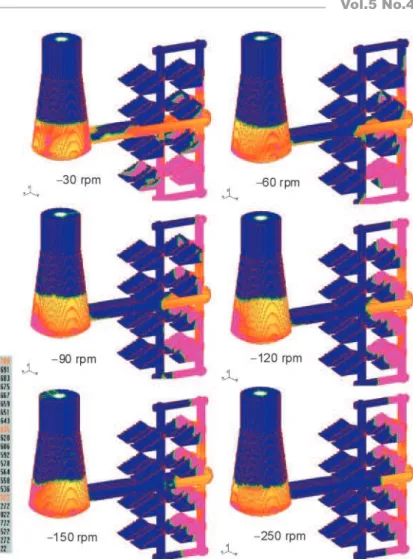
an additional group of computations with different clockwise mold-rotation rates corresponding to those in Fig. 7 were performed using the full mathematical model. The simulated results and comparisons with those at the corresponding counterclockwise mold-rotation rates are shown in Fig. 9 and Fig. 10, respectively.
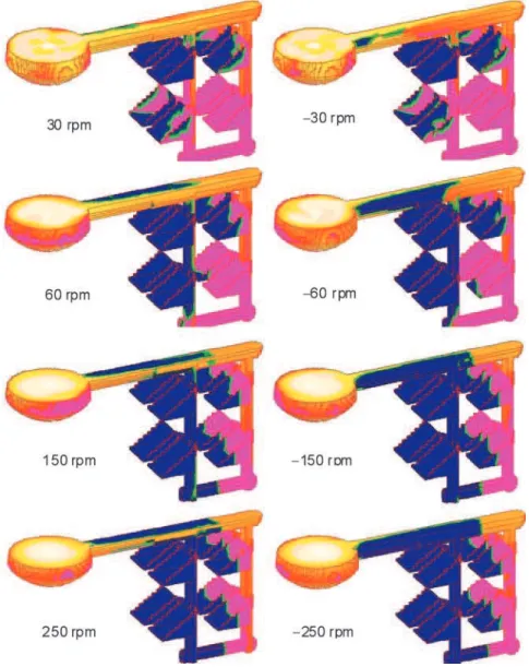
From Fig. 9, it can be seen again that, except for the melt flow behavior in the horizontal r u n n e r s , t h e f i l l i n g V O F -patterns in casting-part cavities are almost the same as both those of Fig. 7 and Figs. 5 and 6 for the corresponding mold-rotation rates. However, due to the clockwise mold-turning direction for the mold-filling c a s e s o f F i g . 9 , the flowing alloy melts in the horizontal runners keep touching the left-s i d e w a l l left-s , r a t h e r t h a n t h e right-sides of the runners as s h o w n i n F i g . 7 . F i g u r e 1 0 g i v e s a c l e a r e r c o m p a r i s o n b e t w e e n t h e h o r i z o n t a l -runner flowing behavior, in a horizontally sectioned view through the runner axes, with different turning-directions for t h e d i f f e r e n t c o r r e s p o n d i n g rotating-velocities. Furthermore, t h e C o r i o l i s a c c e l e r a t i o n i s dependent on both the directions and magnitudes of the rotation rate and the velocity. With the mold-rotation rate increasing, the alloy melts should be more likely to touch the side-walls of the horizontal-runners while filling the mold-cavity of the far end.
This is also clearly confi rmed by
the comparisons of the calculated results made in Fig. 10 for the different mold-rotation rates.
Fig. 7 Comparisons among the simulated centrifugal-mold-fi lling behaviors (an
Fig. 8 Analytical predictions for the free surface
curves of a fl uid medium rotating steadily
at different rotation-rates
4 Conclusions
The present computer codes, 3DLX-WSIM, employing the coupled mathematical model of Eqs. (1) to (5) and a SOLA-VOF algorithm under a rotating coordinate system, has been shown to be available for the numerical simulation of a centrifugal mold-filling and coupled heat-transfer processes. The computational results for the
mold-fi lling behavior of Ti-6Al-4V melt in
a vertical centrifugal-casting process with two horizontal plate-casting cavities show a reasonable agreement with the experimental observations performed in the literature [22].
The present numerical investigations
Fig. 9 Comparisons among the simulated centrifugal-mold-fi lling
behaviours (a outside view) in the Fig. 2(b) mold-cavity with different clockwise rotation rates from -30 to -250 rpm using the full model of Eqs. (1) - (5) (with gravity and centrifugal +Coriolis forces).
also indicate that, due to the dependency of the Coriolis force on the direction and magnitudes of the rotation rate and the
velocity, the mold-fi lling-pattern variations in the cavity-parts,
that directly connect to the vertical sprue and have a large horizontal-section area, in a vertical centrifugal-casting system may be highly sensitive to the processing-parameters (e.g. ωo,
Vo, etc). To avoid the formation of possible related
casting-defects, such as gas-holes/inclusions, entrapments, cold shuts, etc., a more complex gating system should be designed that
can avoid the direct casting-cavity-fi lling occurring. A “turn-back” mold-fi lling technique, which only takes advantage of
the centrifugal force in a transient rotating melt system, has been shown again to be a rational vertical centrifugal-casting process, in order to achieve a smooth and layer-by-layer
casting-cavities-fi lling control.
References
[1] Kumar R L. Process Variable and Quality Control in the Centrifugal Casting of Copper Alloys. The British Foundryman, 1971(1): 27-29.
[2] Zhang Baiming. Centrifugal Casting. Beijing: China Machine Press, 2004. (in Chinese).
[3] Li Xinian. Technology and application of vertical centrifugal
casting. Foundry Technology, 1999 (1): 10-13. (in Chinese) [4] Filin Y A and Isaev A S. Casting of New Alloys for Marine
Vehicles. Leningrad, former Soviet Union: Ship Manufacture Publishing Co., 1971: 196-204.
[5] Qiao Dongfu. Titanium investment casting for large size housing type structure of thin wall. Materials Engineering, 1989(2): 19-22.
[6] Choudhury A and Blum M. Economical production of titanium-aluminide automotive valves using cold wall induction melting and centrifugal casting in a permanent mold. Vacuum, 1996 (47): 829-837.
[7] Nan Hai, Xie Chengmu, et al. The study of large thin-wall complex integrated titanium precision casting. China Foundry Equipment and Technology, 2001(2): 12-14. (in Chinese) [8] Wu M and Sahm P R. Numerical study of porosity in titanium
dental castings. Journal of Materials Science: Materials in Medicine, 1999 (10): 519-525.
[9] Kim M G, Sung S, Y, Lee G C, Park J P, and Kim Y J. Investment casting of near-net shape gamma titanium aluminide automotive turbocharger rotor. Materials Science Forum, 2005, 475-479: 2547-2550.
[10] Li Xin. A Study on Numerical Simulation of Mold-fi lling and Solidifi cation Process of Centrifugal Castings [Dissertation]. Harbin Institute of Technology, 2001: 15-41.
[12] Xu Daming, Li Xin, et al. Numerical simulation of mold-filling behaviors under centrifugal forces. Chinese J. of Mechanical Eng., 2003, 39(3): 146-150.
[13] Zeng Xingwang. S i m u l a t i o n t o P r a c t i c a l F l o w i n g P r o c e s s o f Centrifugal Casting [Dissertation]. Huazhong University of Science &Technology, 2004: 50-53.
[14] Zeng Xingwang, Chen Liliang, and Liu Ruixiang. Study of the numerical simulation of the centrifugal casting. Foundry, 2004, 53 (4): 310-313. (in Chinese)
[15] Wu Shiping, Li Changyun, Guo Jingjie, et al. Numerical simulation of melt mold fi lling during centrifugal casting of ti alloy casting. Rare Metal Materials and Engineering, 2005, 34 (3): 609-612.
[16] Jakumeit J, Laqua R, Hecht U, Goodheart K, and Peric M. Coupled Mold Filling and Solidification Simulation Applied to Centrifugal Casting of TiAl Parts. In: Jones, H. Sheffi eld, eds. SP07-Proc. of the 5th Decennial Int. Conf. on Solidifi cation Processing, July 2007: 292-296. [17] Goldstein H. Classical Mechanics.
2nd ed. Reading, Massachusetts:
A d d i s o n - W e s l e y P u b l i s h i n g Company, Inc. 1980: 177-183. [18] Li Changyun, Wu Shiping, Guo
Jingjie, et al. Hydraulic modeling of mould fi lling behavior during vertical centrifugal casting processing. Int. J. Cast Metals Research, 2006, 19(4): 237-240.
[19] Cross M, Pericleous K, Croft T N, et al. Computational modeling of mold fi lling and related free-surface fl ows
in shape casting: an overview of the challenges involved. Metal. Mater. Trans. B, 2006, 37B: 879-885.
[20] Hirt C W and Nichols B D. Volume of fluid (VOF) method for the dynamics of free boundaries. J. of Computational Phys.,1981, 39: 201-225.
[21] Nichols B D, Hirt C W, and Hotchkiss R S. SOLA-VOF: A Solution Algorithm for Transient Fluid Flow with Multiple Free Boundaries. Tech. Report LA-8355, Los Alamos Scientific Lab, 1980.
[22] Suzuki K, Nishikawa K, and Watakabe S. Mold filling and
Fig. 10: Comparisons between the centrifugal-mold-fi lling behaviors (a
horizontally-sectioned view) in the Fig. 2(b) mold-cavity rotating at different rotation rates and different turning-directions using the full computational model of Eqs. (1) - (5).
solidifi cation during centrifugal precision casting of Ti-6Al-4V alloy. Materials Transactions, JIM., 1996, 37(12): 1793-1801. [23] Jia Liming. Experiment Analyses on Solidifi ed Structure and
Mechanical Properties in Centrifugal Precision Titanium Castings [Dissertation]. Harbin Institute of Technology, 2006: 9-12.
[24] Xu Daming, Li Xin, An Geying, et al. Computer simulation for centrifugal mold fi lling of precision titanium castings. China Foundry, 2004, 1 (1): 53-57.
![Fig. 4 Comparisons between simulation results (a) & (c) and quoted experimental observations (b) & (d) [22] for centrifugally cast horizontal plates of Ti-6Al-4V (20 % partially-fi lled) with a mold rotation-rate of 200 rpm:](https://thumb-eu.123doks.com/thumbv2/123dok_br/18160124.328686/5.918.88.812.124.423/comparisons-simulation-experimental-observations-centrifugally-horizontal-partially-rotation.webp)