ISSN 1546-9239
© 2010 Science Publications
Corresponding Author: Kamaruzaman Jusoff, Department of Forest Production, Faculty of Forestry, University Putra Malaysia, Serdang, 43400, Selangor, Malaysia Tel: +603-89467176
Lead Free Solder Joint Thermal Condition in Semiconductor Packaging
1
M. Najib Harif,
2Allina Nadzri and
3Kamaruzaman Jusoff
1
Department of Physics, Faculty of Applied Science, University Technology MARA,
72000 Kuala Pilah, Negeri Sembilan, Malaysia
2
Department of Physics, Faculty of Applied Science,
University Technology MARA Pahang, 26400 Jengka, Pahang, Malaysia
3
Department of Forest Production, Faculty of Forestry, University Putra Malaysia,
UPM 43400 Serdang, Selangor, Malaysia
Abstract: Problem statement: Solder joints are responsible for both electrical and mechanical connections. Solder does not have adequate ductility to ensure the repeated relative displacements due to the mismatch between expansion coefficients of the chip carrier and the circuit board. Solder material plays a crucial role to provide the necessary electrical and mechanical interconnections in an electronic assembly. Finding a technique to increase the service life of future connections is not the total solution. A method must be developed for predicting the remaining service life of many joints already in use. Approach: The effect of High Temperature Storage (HTS) on lead free solder joint material for ball grid array application using pull test method is studied in this study. Some statistical analysis base on the pull test data also discussed. Three samples of different lead free solder joint material were selected in this experiment namely Sn3.8Ag0.7Cu (SAC387), Sn2.3Ag0.08Ni0.01Co (SANC) and Sn3.5Ag. After the thermal condition test, all the lead free solder joint material samples were tested using Dage 4000 pull test machine. Each pull test will be 5 units and each unit contains 8 balls. Results: The mean pull strength for high temperature storage is 2847.66, 2628.20 and 2613.79 g for Sn3.5Ag, SANC and SAC387, respectively. Thus, Sn3.5Ag shows a significantly better solder joint performance in terms of joint strength compare to SANC and SAC387. Hence, Intermetallic Compound (IMC) thicknesses were measured after cross-sectioning. Sample size for cross-sectioning was 3 units per read point, 2 balls per unit and 3 maximum IMC peaks per ball and the measurement using high power scope of 100x and Image Analyzer software to measure the IMC thickness. For high temperature storage, result show that the mean IMC thicknesses for SAC387, SANC and Sn3.5Ag are 3.9139, 2.3111 and 2.3931 µm. Conclusion/Recommendations: It was found that IMC thickness for SANC and Sn3.5Ag does not show significant growth after high temperature storage but SAC387 demonstrated significant growth Lower intermetallic thickness implies less brittle joint effect, thus from this part of study, better joint reliability is expected for the Sn3.5Ag solder system.
Key words: Solder joint, lead free, pull test, thermal and IMC thicknesses
INTRODUCTION
Surface Mount Technology (SMT) is enabling microelectronic packaging densities and lighter weight. These stringent constraints and demands have raised great concern and importance on the reliability (Lau and Pao, 1997). Solder joints are responsible for both electrical and mechanical connections. Solder does not have adequate ductility to ensure the repeated relative displacements due to the mismatch between expansion coefficients of the chip carrier and the circuit board. Solder behavior involves a creep-fatigue interaction,
making it a poor material for mechanical connections. Finding a technique to increase the service life of future connections is not the total solution. A method must be developed for predicting the remaining service life of many joints already in use. The major concern is the structural integrity of the solder interconnects when subjected to thermal cycling loading (Pang et al., 2001).
(Erich and Coyle, 1999). The ball shear test is being widely used as a test method for accessing the integrity of the solder ball attachment on area array packages. In some of the studies, this method has also been used to compare the effect of aging on shear strength for various lead free alloys (Santos et al., 2002). It is desirable that there is a good metallurgical bond formed between the solder and the substrate. However, due to the brittle nature of the intermetallic layer and the mismatch of physical properties (such as the coefficient of thermal expansion and the modulus of elasticity) between the IMC and the solder matrix, excessive intermetallic growth often degrades the interfacial integrity. This might result in deleterious effect on the reliability of the solder joint. With increasing miniaturization and more input/output terminals in packaging, Integrated Circuit (IC) devices with high-density substrates generate more heat during service. The heat is dissipated through the solder joints and this could result in temperature increase in the joints. This higher temperature has the capability to accelerate the diffusivity of elements in the solder joints and can lead to IMC layer growth at the interface (Alam et al., 2009). The strength of the solder ball attachment is influenced by many factors including pad finish, solder alloy, properties of intermetallic compound formed and assembly processing parameters. For higher reliability, it is important to analyze the lead free BGA solder joint for the effects of the factors just mentioned. Hence, the main factor of this study is the time parameters of temperature storage which is 24, 48, 96 and 168 h.
The purpose of this study is to discuss a new method to discover the effects of mechanical properties for HTS on lead free solder joint material strength. In the past, lead free solder joint material on Ball Grid Array (BGA) have been extensively studied using shear strength method. In this study, Dage 4000 series pull test machine has been used on this study.
MATERIALS AND METHODS
The preparation of the test samples was initiated by applying flux on the solder pads through pin transfer mechanism. The solder balls were placed on the solder pads by ball bump tool. The flux holds the solder balls in place until they are reflowed. The test sample was then reflowed where upon the solder balls formed bumps. During reflow, the ball self centered on the substrate pad (Sykes, 2005). Figure 1 shows the experiment procedure flow diagram for the experiment and Table 1 shows the package information used in this study.
In this study, the lead-free solder balls with composition of SAC387, SANC and Sn3.5Ag were reflowed on solder pads with Ni/Au surface finish using the lead free standard reflow profiles. For each test condition, 40 solder spheres were pulled tested by Dage 4000 series. Ball pull test is a new destructive method to determine the ability of BGA solder balls to withstand mechanical strength. Ball pull test method using a jaw to clamp or pull off the solder ball from the pad substrate. The Dage 4000 series pull test has a unique jaw that also was specifically designed for the size of the ball to be tested.
The processes for the pull test are as shown in Fig. 2. To initiate the test: (a) changing the bump pull jaw correctly. (b) Position the test piece under the microscope; make sure the jaw opening width should be set to be suit the ball size. (c) Bring the jaw down to the part and test the action with specific speed.
Fig. 1: Experimental flow diagram
Table 1: Package information
Package type Package size Solder ball composition
Tape Ball Grid Arrays (TBGA) 0.76 mm ball diameter Sn: 95.5%, Ag: 3.8%, Cu: 0.7%
(30 mils), 1.27 mm pitch, Sn: 97.6%, Ag: 2.3%, Ni: 0.08%, Co: 0.01%
37.5×37.5 package size Sn: 96.5%, Ag: 3.5%
In this study, the highest speed was used, 5000 um sec−1 respectively. However, always take care to align the jaw to the ball. Lastly all the data have been collected and analyzed using general factorial design of experiment analysis.
For IMC thickness measurement, the specimens were cross-sectioned including mounting, grinding and polishing for better observation and examination under high power 100x scope and Image Analyzer software to measure the thicknesses. Sample size for cross-sectioning is 3 units per read point, 2 balls per unit and 3 maximum IMC peaks per ball.
RESULTS
The results for the general factorial design of experiment analysis were carried out using the statistical software, MINITAB™. This analysis identifies which factors and interactions are significant. Factors noted as “significant” represent the independent process variables that have the greatest influences on a particular treatment response (Santos et al., 2002).
DISCUSSION
In addition, ball pull method is widely acknowledged by the industry in the recent years to fully determine the weak interface and the joint strength. Ball pull is found to be more stringent than ball shear because of the pulling mechanism that minimizes ball deformation above the bond site, as well as causes the bond not to be supported by the solder pad cavity wall, thus exposes the true bond strength. In the case of ball shear, higher ball deformation above the bond site is found at the peak of shear force which will result in smaller test area and support from solder pad cavity wall could substantially shield a bad bond from failing (Sykes, 2005).
Table 2 show the summary of the main factors which is significant influenced the mean pull strength. Also, the common unit of strength is gram (g).
Figure 3 shows the interaction plot of strength for the three different materials that have been used for this study. All the materials were kept in the High Temperature Storage (HTS) condition at 150°C. Result shows that all the three material give the significant result. The strength for the pull test clearly decreases when the materials were baked until 168 h.
Table 2: Main factors for the pull test method
Factors Type Levels Values
Time Fixed 4 24, 48, 96 and 168h
Material Fixed 3 SAC387, SANC, Sn3.5Ag
Fig. 3: Interaction plot of strength for three materials at 150°C
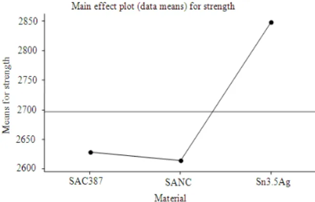
Fig. 4: Mean of strength for three material samples
Many of the physical failure modes was caused by the high thermal mechanic stress which is weigh with chemical reaction that can be weakened the bond structures (Tummala, 2001).
Fig. 5: Main effect interval plot of IMC thicknesses
This is because, solder joint strength is depend on the Cu ingredient changes in the solder ball material. When high temperature storage, Cu will absorb from the solder to Ni bond pad for IMC process. This is will change the Ni bond pad structure suddenly spurted beyond affected kinetic growth for the IMC. In addition of 3.5Ag wt% ability content is closely to eutectic solution reaction and small scale eutectic structure was pliable (Li et al., 2005). Intermetallic Compound (IMC) thickness is one of the major concerns to predict the solder joint reliability. It is reported that higher IMC thickness will cause the joint to be more susceptible to brittle failure. The thicker the IMC layer at the interface, the lower the shear strength of the joint (Jeong et al., 2004). Part of this study was focused on IMC cross-sectioning measurement using high power scope of 100x and Image Analyzer to measure the IMC thickness.
Figure 6 also shows for each thermal aging time, SANC and Sn3.5Ag don’t show much significant growth IMC compare to SAC387. Lower intermetallic thickness for Sn3.5Ag implies less brittle joint effect. Therefore from this part of study, better joint reliability is expected for the Sn3.5Ag solder system. This is because Cu and Sn factor structure of the metal provides a relatively fast reaction compared to Ni and Sn time changes in high-temperature storage tests (Kang et al., 2005). As the rate of reaction for Ni and Sn are very slow compared with Cu and Sn, the first layer is formed IMC, the phase of (Cu,Ni)6Sn5 and secondary IMC layer formed next phase (Ni,Cu)3Sn4. Although there are many sources of Ni and Sn compound layer on the interface, once an initially Cu-Sn IMC layer is formed, probably due to the phase of (Cu,Ni)6Sn5 have a more stable thermodynamic properties of (Ni, Cu)3Sn4. Hence, the existence of low-energy interface between Cu6Sn5 and Ni and high Cu concentrations (0.2-0.6 wt%), so that Ni3Sn4 precipitation will be stunted (Paik et al., 2004; Jeon et al., 2003).
Fig. 6: IMC thicknesses plot for HTS condition
Otherwise the reaction between copper and solder material SAC will be formed the intermediate compounds called Kirkendall void on Cu3Sn/Cu surface layer and on Cu3Sn itself. This Kirkendall void will lead to the phenomenon of brittleness material interface and thus affect the reliability connection (Chiu et al., 2004). Therefore, it can be observed SAC387 solder material thickness provides a high compared to other copper materials. Dual layer structure (bi-layer) is formed due to chemical reaction between materials in Cu and Ni on Ni/Au bond pad are also evidence of the formation of a thick layer of IMC for SAC387 (Zeng et al., 2005). This situation does not occur in the IMC layer of material SANC and Sn3.5Ag which there is no material that will react with Cu and Ni on Ni/Au layer to form a bi-layer. It is clearly shown that the interfacial IMC layer thicknesses increased with aging time. This can be attributed to the diffusion of Cu with time that helped to increase the IMC layer growth (Alam et al., 2009).
In Fig. 5 and 6 it shows that SANC solder materials and thicknesses of IMC Sn3.5Ag have a fairly similar. This is due to the solder material which has SANC percentage of Ni and Co is relatively small, namely less than 0.1% weight. In this case, Ni and Co cannot be said to contribute any direct impact on changes in layer thickness of IMC (Harper, 2005). Thus the nature of physical materials SANC seems similar to the nature of physics Sn3.5Ag solder materials.
CONCLUSION
strength. In summary, the joint strength for all three lead free material decrease when the increasing storage time from 24-168 h at 150°C. Pull test method is one of the good techniques to characterize the solder joint strength for all condition. This technique can also be good recommendations for electronic industry. Somehow a new technique can be used for characterize the lead free solder joint in the future research.
ACKNOWLEDGEMENT
The authors gratefully acknowledge the Ministry of Science, Technology and Innovation for supporting this project through IRPA 03-02-02-0121PR0075/09-01: The Development of the New Methodology in Material Characterization for Semiconductor Packaging.
REFERENCES
Alam, M.E., S.M.L. Nai and M. Gupta, 2009. Effect of amount of Cu on the intermetallic layer thickness between Sn-Cu solders and Cu substrates. J. Elect. Mater., 38: 2479-2488. DOI: 10.1007/s11664-009-0925-x.
Chiu, T.C., K. Zeng, R. Stierman, D. Edwards and K. Ano, 2004. Effect of thermal aging on board level drop reliability for Pb free BGA packages. Proceeding of the IEEE Electronic Components and Technology Conference, June 1-4, IEEE, Las
Vegas NV., pp: 1256-1262.
http://cat.inist.fr/?aModele=afficheN&cpsidt=1780 5213
Erich, R. and R.J. Coyle, 1999. Shear testing and failure mode analysis for evaluation of BGA ball attachment. Proceeding of the IEEE/CPMT Electronic Manufacturing Technology Symposium, Oct. 18-19, IEEE Xplore Press, USA., pp: 16-22. DOI: 10.1109/IEMT.1999.804791
Harper, C.A., 2005. Electronic Packaging and Interconnection Handbook. 4th Edn., Mc-Graw Hill, New York, ISBN: 10: 0-07-143048-2, pp: 554. Jeon, Y.D., A. Ostmann, H. Reichi and K.W. Paik,
2003. Comparison of interfacial reactions and reliabilities of Sn3.5Ag, Sn4.0Ag0.5Cu and Sn0.7Cu solder bumps on electroless Ni-P UBMs. Proceeding of the Electronics Component and Technology Conference, May 27-30, IEEE Xplore Press, USA., pp: 1203-1208.
Jeong, S.W., J.H. Kim and H.M. Lee, 2004. Effect of cooling rate on growth of the intermetallic compound and fracture mode of near eutectic Sn-Ag-Cu/Cu Pad: Before and after aging. J. Elect. Mater., 33: 1530-1544. DOI: 10.1007/s11664-004-0095-9
Kang, S.K., D. Leonard, D.Y. Shih, L. Gignac and D.W. Henderson, 2005. Interfacial reactions of SnAgCu solders modified by minor Zn alloying addition. j. Elect. Mater., 35: 479-485. DOI: 10.1007/BF02690535
Lau, J. and Y.H. Pao, 1997. Solder Joint Reliability of BGA, CSP, Flip Chip and Fine Pitch Assemblies. 1st Edn., McGraw Hill, New York, ISBN: 0-07-036648-9, pp: 329.
Li, X.Y., B.S. Wu and X.H. Yang, 2005. The formation and evolution of IMC and its effect on the solder joint properties. Proceeding of the 6th International Conference on Electronic Packaging Technology, Aug. 30-Sept. 2, IEEE Xplore Press, USA., pp: 273-278. DOI: 10.1109/ICEPT.2005.1564664 Paik, K.W., Y.D. Jeon and M.G. Cho, 2004. Interfacial
reactions and bump reliability of various Pb-free solder bumps on electroless Ni-P UBMs. Proceeding of the Conference Electronic Components and Technology, June 1-4, IEEE Xplore Press, USA., pp: 675-682. DOI: 10.1109/ECTC.2004.1319411
Pang, H.L.J., K.H. Tan and X.Q. Shi, 2001. Microstructure and intermetallic growth effects on shear and fatigue strength of solder joints subjected to thermal cycling aging. Mater. Sci. Eng. A., 307: 42-50. DOI: 10.1016/S0921-5093(00)01958-4 Santos, D., S. Saiyed and F. Andros, 2002. Effect of
reflow profile on shear strength of Sn/4.0Ag/0.5Cu solders spheres for ball grid array applications. J. Surface Mount Technol. Assoc., 15: 25-31.
Sykes, R., 2005. Pull testing of solder balls on BGA and CSP packages without reflow. Dage Precision Industries Ltd.
http://www.dage.de/download/papers/pull_testing_ of_solder_balls_paper.pdf/
Tummala, R.R., 2001. Fundamentals of Microsystem Packaging. 1st Edn., Mc-Graw Hill International, ISBN: 978-0071371698, pp: 344-346.