Interface microstructure of alumina mechanically metallized
with Ti brazed to Fe–Ni–Co using different fillers
R.M. Nascimento
a,∗, A.E. Martinelli
a, A.J.A. Buschinelli
b, E. Sigismund
c,1 aUniversidade Federal do Rio Grande do Norte, Departamento de Engenharia de Materiais,CP. 1524, Campus Lagoa Nova, Natal, RN 59072-970, Brazil
bUniversidade Federal de Santa Catarina, Departamento de Engenharia Mecˆanica, Laborat´orio de Soldagem,
Labsolda, CP. 476 Campus Trindade, Florian´opolis, SC, Brazil
cForschungszentrum Juelich (FZ-Juelich), ZAT, Germany
Received 20 April 2006; received in revised form 11 February 2007; accepted 12 February 2007
Abstract
Ceramic/metal brazing can be carried out either directly using active metal filler alloys or indirectly. In this case, the ceramic surface is metallized by an active metal prior to joining using active-metal free alloys. Although direct brazing is a quite versatile technique, active filler alloys, usually containing Ti, are rather costly materials. With the recent development of new and simple metallizing techniques, reliable joints have been made at reduced costs, thus widening the range of potential applications for ceramic/metal components. In particular, the mechanical metallization with Ti tools has been successfully applied at lab scale to both oxide and non-oxide ceramics. In particular, alumina/metal joints have been thoroughly studied using a variety of commercially available active metal free fillers. Nonetheless, the effect of the filler composition on the microstructure of the joint interface is still under current investigation. In this scenario, the present study reports on the microstructure of interfaces resulting from indirectly brazing mechanically metallized alumina to Fe–Ni–Co. Brazing was carried out under high vacuum (3.0×10⁻⁵mbar) using commercial
Ag–Cu, Ag–Cu–Pd and Au–Ni filler alloys. The results revealed that all active metal free alloys tested wetted and brazed metallized alumina to Fe–Ni–Co. The choice of filler determined different brazing temperature ranges. The microstructure of the interfaces was similar to that obtained by direct brazing and basically consisted of a reaction layer and intermetallics. The reaction layer was formed as a result of the interaction of the Ti layer coating the surface of alumina with the filler alloy and the species of the dissociated ceramic. The use of Ag–Cu–Pd resulted in higher contents of intermetallics comparing to the other fillers.
© 2007 Elsevier B.V. All rights reserved.
Keywords: Brazing; Metal/ceramic; Mechanical metallization
1. Introduction
Ceramic/metal joining processes are under constant improve-ment. Novel approaches as well as fine-tuned well established techniques have been reported, especially aiming at reducing costs for large batches and improving the reliability of joined components, thus fulfilling the requirements for a growing num-ber of applications from industrial and electronic components to biomaterials[1–5]. Recent reports have undoubtedly pointed out to the strict relationship between market improvement of struc-tural ceramics and the technological advances on metal–ceramic,
∗Corresponding author. Tel.: +55 84 3215 3768; fax: +55 84 3215 3768.
E-mail address:[email protected](R.M. Nascimento). 1 In memoriam.
ceramic–ceramic and metal–composite ceramic joining [6–12].
Ceramics can be joined to metals using organic or glassy adhesives, as well as by mechanical joining, solid-state bonding and brazing. Each approach has its own field of applications. Joined structural devices that require interfaces with high ther-mal resistance combined with mechanical strength are usually diffusion bonded or brazed together[10,13]. Reliable strength, high operational temperatures, excellent thermal and electrical conductivity often characterize brazed ceramic/metal couples. In addition, brazing is a relatively simple process and easily auto-mated[14,15]. Brazing can be carried out in a single step (direct brazing) using active filler alloys containing Ta, Nb, V and, espe-cially, Ti. The presence of active metals reduces and wets the surface of ceramics which are then chemically joined to metallic counterparts. Recent studies have contributed to reveal the
anisms involved in the reaction of the Ti present in the filler alloy with the surface of engineering ceramics, especially alumina, zirconia and silicon nitride[4,10,14]. Alternatively, the ceramic component can be previously metallized and then brazed using conventional active-metal free filler alloys[4,15–18].
The mechanical metallization of oxide ceramics is a recently patented method developed in the Forschungszentrum J¨ulich, Germany[19]. It consists of coating ceramic surfaces with active metal films, mainly Ti, deposited as a result of the wear of a high-speed turning tool bit against the surface of the ceramic. High temperatures and hazardous emissions of gases are not involved, since the process is flux-free. In addition, no specific equipment is required to automatically metallize either small or large batches[19].
This study addressed the effect of the use of differ-ent active-metal free filler alloys on the microstructure of Al2O3 mechanically metallized with Ti and then brazed to Fe–Ni–Co (Vacon 70). This alloy is similar to kovar and was selected because of its wide range of applications involving ceramic/metal joints[14]. Furthermore, its coefficient of ther-mal expansion (8.2×10⁻⁶◦C−1at 20–600◦C) is similar to that of alumina (8.6×10⁻⁶◦C−1at 20–1000◦C), thus reducing the thermal mismatch between the ceramic and metal, ultimately minimizing the residual stresses developed upon cooling of the joined component from the relatively high brazing temperatures.
2. Experimental procedure
Alumina samples were mechanically metallized with Ti, brazed to Fe–Ni–Co (Vacon 70) using different active-metal free filler alloys and characterized using microstructural meth-ods. The ceramic counterparts of the brazed couples consisted of cylindrical samples 8.08 mm in diameter manufactured from 99.7% pure alumina provided by W. Haldenwanger Teschnische Keramik GmbH & Co. (ρ= 3.75–3.94 g/cm3; Ra= 0.54±0.07m), and used as received. The metallic counterpart of the joints consisted of commercial Vacon 70 with composition Fe–29.5%Ni–23%Co, complying with 1.3982–NiCo2823 DIN 17745 SEW 385 guideline. Three dif-ferent filler alloys were selected. They were all commercially available as metal sheets (Degussa, Germany). The selection of alloys took into consideration their melting temperature and conventional brazing temperature ranges, i.e., 800–900◦C (VH-780), 850–950◦C (SCP-2) and 950–1100◦C (VH-950). A summary of some characteristics of the filler alloys used is listed inTable 1(supplier’s data).
The metallization assemble was set-up using a mechanical lathe, as schematically shown inFig. 1. The ceramic piece was
Fig. 1. Schematics of mechanical metallization set-up of ceramic surfaces.
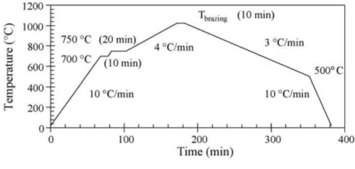
Fig. 2. Brazing cycle.
attached to the lathe that turned counterclockwise under con-stant and pre-established speed. A titanium rod was machined to a cone-shaped bit and attached to a high-speed straight grinder which turned clockwise. The contact between the turn-ing parts (ceramic surface and Ti cone) worn out the metallic tool thus depositing a titanium layer onto the ceramic surface. A detailed study about the effect of the metallization parameters on the quality of deposited films[20–22]guided the choice of parameters used herein, i.e. lathe speed 800 rpm; rectifier speed 27,000 rpm and metallization time 60 s. Under these conditions, the deposited films do not oxidize. Their thickness is 5±2m, as measured by SEM images.
Prior to brazing, the joining counterparts were cleaned in ultrasonic acetone bath. Brazing was carried out in a resistive furnace under high vacuum. The pressure was maintained below 2.0×10⁻⁵mbar (2.0×10⁻³Pa) during the entire cycle. The brazing thermal cycle is represented inFig. 2. The choice of filler alloy and brazing temperature altered only the top constant temperature step, as shown inTable 2.
Table 1
Characteristics of the filler alloys (manufacturer’s data)
Alloy trade name ISO 3677 designation Ag (wt.%) Cu (wt.%) Pd (wt.%) Au (wt.%) Ni (wt.%) Tmelt(◦C) (sol/liq) Sheet thickness (mm)
VH-780 B-Ag72Cu-780 72 28 – – – 780 0.05
SCP-2 B-Ag58CuPd-824/852 58.5 31.5 10.0 – – 824/852 0.1
Table 2
Upper brazing temperature Vacon 70/Al2O3
Ag–Cu 820◦C
Ag–Cu–Pd 870◦C
Au–Ni 990◦C
Au–Ni 1025◦C
The brazing counterparts were held together to yield the intended geometry of the joint and assure proper alignment (Fig. 3). The joints were designed to comply with the sample geometry required for leaking tests carried out using a He Ley-bold VL 200 leaking detector. The metallic part of the joint was sealed in a pumping system by its central opening, keeping the inner part of the brazed joint under vacuum. A He needle was then used to blow the gas all around the joint. The presence of leaking points in the brazed interface allows for the penetration of He into the area under vacuum, which is monitored by a gas spectrometer connected to the set-up.
The hardness and elastic modulus of the phases identified in the ceramic/metal joints was determined by nanoindentation tests performed using a XP Nanoindenter by Nano Instruments (USA). Cross-sections of the brazed joints were mounted in resin, grinded and polished. The individual phases were selected using an optical microscope and indented. The elastic deforma-tion caused by indentadeforma-tion was monitored as a funcdeforma-tion of the applied load thus yielding the elastic modulus of the material.
The microstructure of alumina/Ti/filler/Fe–Ni–Co samples was characterized using a Reichert Jung-Polyvar optical micro-scope, equipped with a digital analysis system (FC-TK – F7300U – JVC), and a Philips XL-30 SEM. All compositions obtained by EDS are reported herein in wt.%. Cross-sections of the samples were cut using a diamond disc, mounted in cold-setting resin, grinded using SiC paper (FEPA guideline P 43-GB-1984: 220, 320, 500, 800, 1200), polished on dia-mond solution (15, 6, 3, 1m) and finished on alumina solution (0.1m).
The mechanically metallized coating layers were also charac-terized by optical microscopy and scanning electron microscopy
Fig. 3. Geometry of brazing couple.
without any prior surface preparation. The structure of the crys-talline phases present on the metallized surfaces was studied by X-ray diffraction using a Philips X-Pert diffractometer.
3. Results and discussion
Brazed alumina/Fe–Ni–Co couples were characterized in order to establish correlations involving the microstructure of the ceramic/metal interfaces and the filler alloy used. Emphasis was placed on the role of the titanium coating on the formation of the reaction layers and precipitation zones encountered adjacent to the ceramic component, as a function of the filler alloy.
All brazed joints displayed adequate visual aspect regard-less of the filler alloy employed and brazing temperature. No misalignments were detected resulting in few usual microstruc-tural joining defects such as voids or local areas depleted of filler. Furthermore, all components tested showed ade-quate vacuum tightness. The leaking rates were lower than 4.0×10⁻⁹mbar l s−1, characteristic of technically sealed com-ponents.
The microstructure of couples brazed at 820◦C using the eutectic Ag–Cu filler alloy was characterized by the presence of a eutectic microconstituent, a reaction layer and intermetallics in the precipitation zone (Fig. 4).
The eutectic microconstituent resembled the original microstructure of the filler alloy which was not affected by reac-tions involving either Ti or Fe–Ni–Co. The composition of the reaction layer was semi-quantitatively determined by SEM/EDX and consisted of 10%Ti, 30%Cu, 10%Ag, 30%Al, 10%O, bal. Fe, Ni and Co. Although SEM images did not reveal the pres-ence of a continuous reaction layer, chemical analyses clearly suggested that Ti was present all along the interface between filler alloy and alumina. Four other phases can also be noticed inFig. 4, i.e., a Cu-rich phase; a phase containing Ti, Cu, Ni and small contents of Co and Fe; a component rich in Ti, Fe and Cu; and a finely dispersed structure.
Similar studies, as well as previous results obtained by this research group on brazed alumina/Fe–Ni–Co using active fillers,
Fig. 4. Precipitation zone of alumina/Fe–Ni–Co sample brazed at 820◦C using
Fig. 5. Alumina/Fe–Ni–Co couple brazed at 870◦C using Ag–Cu–Pd filler.
revealed that Ag–Cu–Ti reacts with Fe–Ni–Co during brazing [14,16,21–23]. As a result, Fe, Ni, and Co can be dissolved by the molten active filler alloy, subsequently precipitating differ-ent phases containing Ti, Cu, Fe, Ni and Co, upon cooling from the brazing temperature. Both the interfacial composition and microstructure of Fe–Ni–Co brazed to alumina mechanically metallized with Ti suggested that the mechanism of phase forma-tion and microstructural development is similar to that observed after brazing using active fillers containing Ti. In other words, the eutectic Ag–Cu reacts with Ti, granting chemical activity to the filler which performs as active filler[22].
The hardness and elastic modulus of similar Fe–Ti and Ni–Ti phases were evaluated by nanoindentation. However, since both phases were characterized by similar contrast and morphology under the optical microscope coupled to the nanoindentation tester, the results reported herein represent average values of hardness for both phases. The average hardness and elastic mod-ulus for those phases was 2.88 and 206 GPa, respectively. These values are typical of brittle intermetallics, deleterious to the mechanical soundness of the brazed joint. The average elas-tic modulus of Cu-rich phases was 130 GPa, which is consistent with its composition.
Alumina/Fe–Ni–Co couples brazed with Ag–Cu–Pd (SCP-2) also displayed the presence of a eutectic component in addition to a precipitation zone containing intermetallics. Little poros-ity was observed. The microstructure of the precipitation zone consisted of a plate-like component (phase 1), a Cu-rich phase (phase 3) originated from the filler alloy eutectic composition, and a second phase (phase 2), all indicated inFig. 5. The chem-ical composition of this region is described inTable 3.
Fig. 6. Alumina/Fe–Ni–Co brazed at 990◦C using Au–Ni.
A considerable number of solid phases have been established along the entire composition range of the binary Pd–Ti system. Moreover, Ti and Pd also form a complex system with approx-imately 13 different crystalline structures, several eutectoid, eutectic, peritectic and peritectoid reactions as well as allotropic transformations [24]. Finally, reactions involving Ti–Pd and Ti–Cu may also result in the precipitation of different com-pounds. From binary and ternary diagrams, phase 3 could be associated to a mixture of Ag–Pd solution solutions and Cu. Phase 2 likely consists of a Ti- and Pd-rich intermetallic of com-position between Ti2Pd and TiPd along with Cu, which affects not only the composition but also the chemical stability of the compound. The main elements present in phase 1 include Cu, Pd and Ti, in addition to Ni and Co. A detailed identification from binaries and ternaries is impaired by its complex nature. The net effect of all these reactions may likely account for the presence of different phases in the precipitation zone, since the reaction for the formation of each one of them depends on the local activity of Ti and Pd.
The microstructure of alumina/Fe–Ni–Co couples brazed using Au–Ni (Fig. 6) is essentially characterized by the mor-phology of eutectic solidification products and a precipitation zone. No reaction layer adjacent to the ceramic surface could be observed.
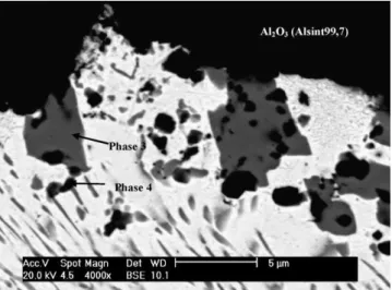
A detailed analysis of this precipitation zone (Fig. 7) revealed the presence of two phases (labeled 3 and 4) dispersed in the eutectic, which consisted of a mixture of an Au-rich matrix (phase 1, composition 86%Au, 9%Ni, 4%Fe and 1%Co (wt%)) and a Au–Ni phase (phase 2, composition 43%Au, 36%Ni, 12%Fe and 9%Co). Although the morphology of phase 3 is quite similar to that of phase 2, the composition of the former, i.e.,
Table 3
Estimated composition of interfacial components (Ag–Cu–Pd/870◦C)
Phase label Characteristics Estimated chemical composition (wt.%)
Phase 1 Plate-like morphology 56%Pd–14%Cu–12%Ti–10%Ni–5%Co–3%Fe
Phase 2 Fine 42%Pd–28%Ti–8%Cu–7,5%O–7%Ni–3.5%Co–2%Al–2%Fe
Fig. 7. Precipitation zone of Fe–Ni–Co/Al2O3joint brazed at 990◦C.
53%Ni, 20%Au, 11%Fe, 11%Co, 3%O, 1%Ti, 1%Al is rather different than that of the latter. Finally, a fourth phase, rich in Ti and having composition 45%Ti, 31%Au, 13%O, 5%Ni, 3%Fe, 2%Co and 1%Al was also detected. The origin of the presence of Ni in the reaction products could not be safely established since the element is encountered in the composition of both filler alloy and Fe–Ni–Co. Increasing the brazing temperature to 1025◦C did not significantly affect the microstructure of the interface. TEM imaging has also been used to identify metal–ceramic interfacial phases, as reported elsewhere[25].
The intimate interaction between Ti and Au accounts for the precipitation of phases 3 and 4 in the Ti-enriched region of the filler alloy. The Au–Ti binary system is characterized by a series of well-established compounds such as Ti3Au, TiAu2, TiAu4and ␣,and␥TiAu, in addition to eutectic, eutectoid and peritectoid reaction products[24].
Phases 1 and 2 originated from the eutectic composition of the filler alloy in addition to small contents of Fe and Co from the dissolution of Fe–Ni–Co. The composition of phase 3 also contained small contents of Ti, Al and O, suggesting that traces of the Ti coating were dissolved by the filler alloy and reacted with Al and O from the dissociation of alumina, hence nucleating phase 3.
Finally, phase 4 contained reasonably high contents of Ti and Au (Fig. 7), and resulted from the reaction between the filler alloy and the coating layer. The presence of Al and O suggested the superficial reduction of the ceramic counterpart, diffusion of Al and O to the filler alloy and reaction with additional Ti present in the precipitation zone.
Each filler alloy used to braze alumina to Fe–Ni–Co resulted in interfacial microstructures with distinct characteristics. Con-siderable formation of rod-shaped Ti–Pd intermetallics was observed in couples brazed using Ag–Cu–Pd (SCP-2), suggest-ing limited mechanical strength. Despite of such drawback, this alloy is recommended to join metals to ceramics metallized by the Mo–Mn process. Couples brazed using mechanically met-allized alumina depicted quite distinct interfacial features. The use of Ag–Cu resulted in microstructures consisting of a thin reaction layer along with finely dispersed intermetallics in the
precipitation zone. This type of microstructure is similar to that obtained from active metal brazing and is unlikely to embrittle the joint, since the reaction layers are not excessively thick, its continuous phase is not brittle and the contents of intermetallics is limited. The use of Au–Ni combined with relatively high brazing temperatures did not reveal the formation of reaction layers. Only a precipitation zone consisting of intermetallics was observed. Therefore, from the microstructural standpoint, brazing at temperatures ∼800◦C should be carried out using the Ag–Cu eutectic filler alloy. Au–Ni should be used for higher temperatures (1000◦C) whereas caution should be taken when using Ag–Cu–Pd to prevent thick interfaces and the extensive formation of intermetallics.
4. Conclusions
Alumina was mechanically metallized with Ti and success-fully brazed to Fe–Ni–Co using different active-metal free filler alloys. The variety of filler alloys tested allowed brazing at a wide temperature range. Based on the microstructural charac-teristics of the resulting interfaces, it could be established that the eutectic Ag–Cu filler was adequate for brazing around 820◦C, whereas the eutectic Au–Ni can be recommended for brazing at temperatures in excess of 1000◦C. The use of Ag–Cu–Pd may result in higher contents of intermetallics comparing to the pre-vious fillers. The following conclusions should also be pointed out:
(1) The interfacial microstructure of joints brazed using Ag–Cu was characterized by a eutectic microconstituent, a thin reaction layer and a precipitation zone containing finely dispersed Ti-rich intermetallics.
(2) No significant differences were observed in the interfacial microstructure of couples brazed using mechanically metal-lized alumina comparing to that of commercially available active Ag–Cu–Ti filler alloy.
(3) Joints brazed using Ag–Cu–Pd revealed the formation of brittle rod-shaped intermetallics rich in Pd–Ti and dispersed in the precipitation zone.
(4) No reaction layer was observed upon brazing using Au–Ni. The resulting interfaces consisted solely of a precipitation zone containing intermetallics.
Acknowledgments
R.M. Nascimento expresses his gratitude to CAPES and DAAD for a scholarship grant and to Dr. R. Lison (in memoriam) for his role in creating the mechanical metallization process and for his encouragement to the present study.
References
[1] W. Tillmann, E. Lugscheider, R. Xu, J.E. Indacochea, J. Mater. Sci. 31 (1996) 445–452.
[2] M.R. Rijnders, S.D. Peteves, Scr. Mater. 41 (10) (1999) 1137–1146. [3] T. Itoh, H. Kimura, J. Eng. Gas Turbines Power 115 (1993) 42–50. [4] M.C.A. Nono, J.J. Barroso, P.J. Castro, Mater. Sci. Eng. A (2006) 435–436
[5] V. Curicuta, D.E. Poulain, D.R. Alexander, R.J. De Anegelis, S. Gasser, E. Kolawa, Mater. Sci. Eng. B 68 (2000) 186–195.
[6] S.D. Peteves, M. Paulosto, G. Ceccone, V. Stamos, Acta Mater. 46 (7) (1998) 2407–2414.
[7] T.H. Chuang, M.S. Yeh, Y.H. Chai, Metall. Mater. Trans. A 31A (2000) 1591–1597.
[8] C. Zhang, G. Qiao, Z. Jin, J. Eur. Ceram. Soc. 22 (2002) 2181–2186. [9] C. Zhang, Y. Zhou, M. Naka, J. Eur. Ceram. Soc. 26 (2006) 3459–3466. [10] L.X. Zhang, J.C. Feng, P. He, Mater. Sci. Eng. A 428 (2006) 24–33. [11] Y.N. Liang, M.I. Osendi, P. Miranzo, J. Eur. Ceram. Soc. 23 (2003)
547–553.
[12] M. Paulasto, J. Kivilahti, J. Mater. Res. 13 (2) (1998) 343–352. [13] K. Suganuma, Mater. Res. Soc. Symp. Proc. 314 (1993) 51–60. [14] K. Suganuma, ISIJ Int. 30 (12) (1990) 1046–1058.
[15] J.T. Klomp, G.De. With, Mater. Manuf. Process. 8 (2) (1993) 129–157. [16] R. Voytovych, F. Robaut, N. Eustathopoulos, Acta Mater. 54 (2006)
2205–2214.
[17] E. Lugscheider, W. Tillmann, Mater. Manuf. Process. 8 (2) (1993) 219– 238.
[18] J. Intrater, Mater. Manuf. Process. 8 (3) (1993) 353–373.
[19] R. Lison, Verfahren zum verl¨oten zweier keramiken oder einer keramik mit einen metal, Patent P.T, 1.1481, Germany.
[20] R.M. Nascimento, A.E. Martinelli, A.J.A. Buschinelli, U. Reisgen, J. Rem-mel, J. Mater. Sci. 40 (2005) 4549–4556.
[21] R.M. Nascimento, A.E. Martinelli, A.J.A. Buschinelli, Cerˆamica 49 (2003) 178–198.
[22] R.M. Nascimento, A.E. Martinelli, A.J.A. Buschinelli, E. Lugscheider, E. Sigismund, Weld. Cutting 2 (2004) 96–107.
[23] R.M. Nascimento, A.E. Martinelli, A.J.A. Buschinelli, A.N. Klein, J. Mater. Sci. 34 (1999) 5839–5845.
[24] G. Petzow, G. Effenberg, Ternary Alloys: A Comprehensive Compedium of Evaluated Constitutional Data and Phase Diagrams, VHC, New York, 1988.