_____________________________
*)Corresponding author: [email protected]
doi:
10.2298/SOS1303313L
UDK 678.046.3
Interface Microstructure of the Brazed Zirconia and Ti-6Al-4V
Using Ti-based Amorphous Filler
Y. Liu, J. Hu, Y. Zhang, Z. Guo
*)Key Lab. of Automobile Materials, Ministry of Education, College of Materials
Science and Engineering, Jilin University, Changchun 130025, China
Abstract:
The polycrystalline ZrO2−3mol.%Y2O3 was brazed to Ti-6Al-4V using a Ti47Zr28Cu14Ni11 (at.%) amorphous ribbon at 1123 K in a high vacuum. The microstructure of the interface and evolution mechanism of the joint was investigated. The experimental result showed that the typical interfacial microstructures of the joints consisted of ZrO2/TiO+TiO2+Cu2Ti4O+Ni2Ti4O/α-Ti+(Ti,Zr)2(Cu,Ni) eutectic/(Ti,Zr)2(Cu,Ni)/acicular Widmanstäten structure/Ti–6Al–4V alloy. The microstructure of the brazed joint was related to the solution and chemical reaction among atoms during brazing. According to the mechanical property tests the joint brazed at 1123 K for 30 min obtained the maximum shear strength 63 MPa. Both the white block intermetallic compound (Ti,Zr)2(Cu,Ni) and the coarse α-Ti+(Ti,Zr)2(Cu,Ni) eutectic structure should be avoided forming in the brazed joint.
Keywords: Brazing; Amorphous filler; Interface; Microstructure.
1. Introduction
Zirconia is an important structural and functional material because of its high strength and fracture toughness [1]. Bonding zirconia to metals is required for some service in industrial utilization. In particular, metal–zirconia interfaces play an important role in an extraordinary variety of industrial and technological applications in a large diversity of fields, such as, heterogeneous catalysis, fuel cells, microelectronics, optoelectronics, structural composites or coatings of nuclear reactors [2]. Ti-6Al-4V alloy is frequently introduced as substrate to be bonded with Zirconia compared with other metals because of its excellent properties such as high specific strength and good corrosion resistance [3]. Furthermore, it can be easily welded, forged and machined. Therefore, bonding zirconia to Ti-6Al-4V is often used in aerospace industries (rocket engines, parts of wings rudders etc.) [4]. Furthermore, both materials have good mechanical properties and are biocompatible. It is for implantable biomedical device, such as chirurgical implants and dental implants [5].
Active brazing is a available method for bonding Zirconia ceramic to metal because the addition of active element in filler metals can effectively improve the wettability of ceramic
[6].One of the most widely used filler metal is based on Cu-Ti system, namely on the
Ag-28Cu eutectic composition, with about 2-5wt% of titanium additions [7-9]. Recently,
active Ti and Zr elements with good glass forming ability that tends to replace the traditional Ag-Cu-Ti filler alloys in some cases. It is well known that the wettability of ceramics by brazing fillers plays a crucial role in their joining process. The Ti-based amorphous fillers have the effective active elements, such as Ti and Zr. Active elements such as Ti diffuse toward the interface between ceramic and filler foil and then are consumed by the reaction with ceramic, which makes for the formation of the reaction products and improves the wettability of ceramics. It has been conducted concerning the wettability and reactivity between the molten metallic-glass-forming alloy and the ZrO2 ceramic.
The current investigation concentrates on the joining of Zirconia ceramic and Ti-6Al-4V alloy using a Ti47Zr28Cu14Ni11 (at.%) amorphous filler. The joint quality depends on the
chemistry and morphology of the reaction layer formed at the ceramic/brazing alloy interface. It is thus important to characterize the interfacial reaction layer and interfacial reaction mechanism.
2. Experimental procedure
The base metal Ti–6Al–4V plate and the sintered ZrO2 pieces used in the experiments
were with the dimensions of 20 mm × 5 mm × 5 mm. The chemical composition in weight percent was 5.76 Al, 4.03 V, 0.28 Fe, 0.06 C and balance Ti. The Ti47Zr28Cu14Ni11 amorphous
foil with a thickness of 50 µm was cut into dimensions of 15 mm × 5 mm. The overlapping length and the clearance of the brazed joint were 15 and 5 mm in the experiment, respectively. The melting temperature of the Ti47Zr28Cu14Ni11 foil was measured to be 1116 K using a
differential scanning calorimeter (DSC, NETZSCH STA 409 PC, Germany).
Both materials were polished with different sizes of diamond pastes. The Ti47Zr28Cu14Ni11 amorphous foil was gently ground with No.1000# SiC sand paper. Before
assembling, the ZrO2, Ti–6Al–4V and Ti47Zr28Cu14Ni11 foil were ultrasonically cleaned in
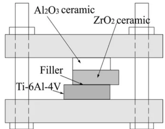
acetone and then they were assembled into a sandwich structure, as schematically shown in Fig. 1. Brazing was performed at isothermal temperature 1123 K in a high vacuum of about ~ 5×10⁻⁴ Pa. The samples were heated at a rate of 20 K/min, holding at the brazing temperature for 30 min, and then cooled at 5 K/min to 600 K, followed by cooling in furnace.
Fig. 1. Schematic of assembling parts for the brazing experiments.
Selected samples were sectioned and polished for microstructural observation using a field emission scanning electron microscope (FESEM, JSM-6700F, Japan) equipped with an energy dispersive spectrometer (EDS). The phases at the interfaces were identified by X-ray
diffraction (XRD, D/2500PC Rigaku, Japan) using a Cu target with Kα radiation. XRD
pattern was performed on the fractured surfaces after the shear test. The shear strength of the
were examined using the FESEM.
3. Results and discussion
3.1 Microstructures
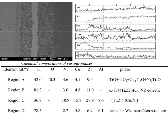
Fig. 2 shows a back-scattered electron image (BEI) of the ZrO2/ Ti47Zr28Cu14Ni11
/Ti-6Al-4V joints brazed at 1123 K for 30 min. Additionally, four regions in the brazed joint and contents distributions of major elements are displayed by line scan analysis and point analysis of EDS. The joint can be divided into four regions of A, B, C, and D. It can be seen from Fig. 2 that the continuous thin reaction layer next to ZrO2 is mainly composed of Ti, Cu, Ni and O.
Layer A also includes some Zr. In the middle of the braze alloy, the black matrix in zone B is Ti-rich phases, while the white strips and small blocks are rich in Cu and Ni phases. The major elements in the large white strip and thick white layer C adjacent to layer B are Ti-Zr-Cu-Ni phases and layer D adjacent to Ti-6Al-4V is Ti and Al-rich phases. This photograph reveals microstructural transition from the substrates to the brazed joint. These regions are formed by atomic diffusion, including isothermal solidification and solid-state diffusion during brazing [14]. Upon heating to the bonding temperature, the braze alloy melts and becomes liquid. The liquid then fills voids formed by unevenness of the overlapped surfaces and can sometimes dissolve residual surface contamination. With time the active elements of the filler diffuse into the parent metal resulting in isothermal solidification. The dissolution process involves oxygen and Zr diffusion from the ZrO2 bulk to the braze alloy. At the same
time, Ti, Al and V in alloy diffuse to the braze alloy. They will form new phases or has solubility for the braze alloy. All microstructures in the joint interface can be classified into four characteristic regions with respect to morphology of microstructure and the result of quantitative EDS analysis. The formation of these regions indicates that the intense reaction of the molten filler metal with the ZrO2 and Ti-6Al-4V occurred during brazing.
Chemical compositions of various phases
Element (at.%) Ti O Ni Cu Zr Al phase
Region A 42.0 40.3 4.6 4.1 9.0 – TiO+TiO2+Cu2Ti4O+Ni2Ti4O
Region B 81.2 – 3.0 4.8 11.0 – α-Ti+(Ti,Zr)2(Cu,Ni) eutectic
Region C 36.8 – 10.9 15.8 27.9 8.6 (Ti,Zr)2(Cu,Ni)
Region D 78.5 – 2.7 5.8 6.9 6.1 acicular Widmanstäten structure
Fig.2. (a) Back-scattered electron image of the ZrO2/Ti–6Al–4V interface zone brazed at
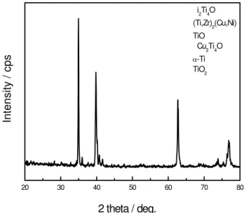
Fig. 3 displays the XRD result of the fractured surfaces after the shear test brazed at 1123 K for 30 min. According to the XRD and EDS results, four regions are discussed as follows:
20 30 40 50 60 70 80
i2Ti4O (Ti,Zr)2(Cu,Ni) TiO
Cu2Ti4O
α-Ti TiO2
2 theta / deg.
Inte
nsity /
cp
s
Fig. 3. XRD pattern for the interfacial reaction product in the joint brazed at 1123K for 30min.
Region A with gray colors is a layer adjacent to the ZrO2 ceramic, thickness of which is
about 8 μm. It is rich in Ti and O, containing few amounts of Cu, Ni and Zr. The XRD result indicates that region A is comprised of TiO, TiO2, Cu2Ti4O and Ni2Ti4O phases. Because
titanium has a high affinity to oxygen, the titanium atoms tends to be aggregated at the zirconia/filler interface. Subsequently, reactions between the oxygen atoms in zirconia and the titanium atoms in the filler occurred, creating a dark, O-deficient ZrO2 region [1]. Because Cu
and Ni have a high affinity to Ti, they are easy to form stable Ti2Ni and Ti2Cu intermetallic
compounds and then react with oxygen, leading to the formation of the Cu2Ti4O+Ni2Ti4O
phases [15]. Oxides of M2Ti4O type with structures like Ti2Ni and Ti2Cu were discovered in
other experiments of bonding alumina by titanium active brazing as well as in this study [16]. These oxides are all metallic. Here, M represents Ni or Cu. The creation of Cu2Ti4O and
Ni2Ti4O favored the filler’s wetting on ZrO2 surface. Being metallic oxide as stated earlier, the
Cu2Ti4O + Ni2Ti4O layer between ZrO2 surface and Ti2Ni + Ti2Cu belt of the filler functioned
as the transition layer keeping some extent of structure consistency. In conclusion, oxide Cu2Ti4O and Ni2Ti4O were the linkage agent on the ZrO2/filler interface.
Region B is a lamellar eutectic microstructure [15] containing Ti–rich phase and a small
amount of Cu, Ni and Zr in the middle of the brazed joint. The XRD result indicates that region B is comprised of α-Ti and (Ti,Zr)2(Cu,Ni) phases. The reason is that Ti2Ni and Ti2Cu
have some solubility of Zr [15], leading to the formation of (Ti,Zr)
2Cu and (Ti,Zr)2Ni phases
that is non-uniformly distributed in the α-Ti phase. It is presumed that these phases are produced by the reaction of dissolving elements of base metal with Cu, Ni and Zr elements of the liquid filler metal. Fig. 2(a) shows the lamellar eutectic microstructure of region B, consisting of dark block α-Ti and bright lamellate (Ti,Zr)2(Cu,Ni).
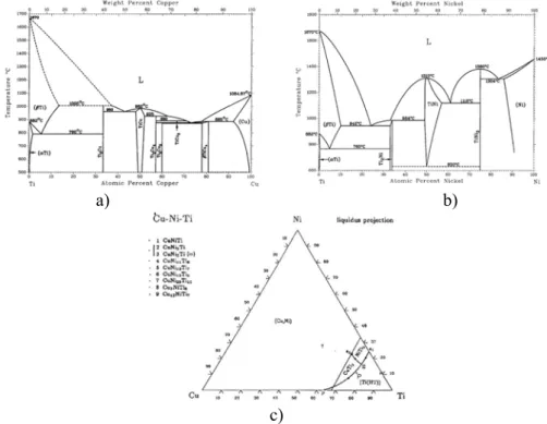
Region D contains an acicular Widmansttten structure adjacent to the Ti–6Al–4V alloy. Ti-6Al-4V is a type of α-β titanium alloy, and the microstructure of the α-β titanium alloy depends on the chemical composition of the alloy [17]. During brazing, diffusion of Cu and Ni atoms from the liquid filler metal into the original α+β base metal transformed the structure into the β phase because the Cu and Ni elements are the β-Ti phase stabilized for the Ti-6Al-4V alloy. When cooled from β phase at 1155 K according to Cu-Ti diagram shown Fig. 4, acicular α phase nucleas at the grain boundary of β phase and then grows as acicular Widmansttten structure.
a) b)
c)
Fig. 4. (a) Cu-Ti phase diagram, (b) Ni-Ti phase diagram and (c) Cu-Ni-Ti ternary alloy phase diagrams in at.%.
3.2 The model of the formation of interface the brazed ZrO
2ceramic/
Ti
47Zr
28Cu
14Ni
11/Ti-6Al-4V alloy joint
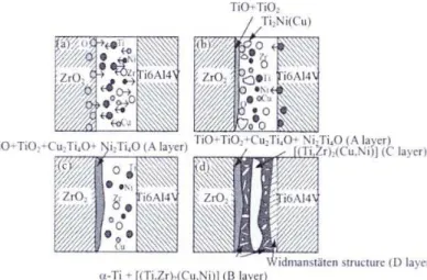
To understand the genesis of different brazes mirostructures, one should consider various metallurgical paths following melting, dissolution/diffusion, crystallization and cooling stages of brazing. Therefore, model for the formation of interface of ZrO2 ceramic/
Ti47Zr28Cu14Ni11/Ti-6Al-4V alloy joint is given in Fig. 5. The whole reaction process is
divided into four stages.
In the first stage (after the braze alloy melts and become liquid), because of the existence of concentration gradient, Ti, Zr, Cu and Ni in braze alloy moved to the interface of ZrO2 ceramic/Ti47Zr28Cu14Ni11 and the interface of Ti47Zr28Cu14Ni11/ Ti-6Al-4V alloy. Active
element Zr reacted with ZrO2 to produce substoichiometric ZrO2-x. The oxygen atoms that
diffused away from the zirconia substrate, continued to move to the interface. The formation of the ZrO2-x reaction was presumed to be a dissolution process involving oxygen diffusion
from the ZrO2 bulk to the molten Ti-base alloy according to the following overall equation
It was attributed to the formation of the substoichiometric ZrO2-x phase which contains
a large number of oxygen anion vacancies. The presence of these vacancies favored further migration of the oxygen anions (see formula (2) [1]).
ZrO2→ZrO2-x + x/2 O2 0≤x≤0.02 (2)
Fig. 5. Interface evolution model for ZrO2 ceramic/Ti–6Al–4V alloy joint brazed with
Ti47Zr28Cu14Ni11: (a) behavior of atoms, (b) formation of TiO +TiO2 oxides and Ti2Ni(Cu)
intermetallic compounds, (c) formation of A layer and (d) formation of B, D layers and precipitation of C layer.
In the second stage, when there is enough Ti at the interface of ZrO2
ceramic/Ti47Zr28Cu14Ni11, active element Ti reacts with O atoms and forms titanium oxides,
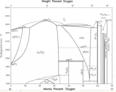
such as TiO, Ti2O and TiO2 oxides. The Ti-O phase diagram, Fig. 6 [18], shows that it is
energetically favourable for α-Ti to dissolve up to 34 at.% oxygen. As the brazing
temperature increases, the amount of oxygen which is capable of going into solid solution also increases. Thus using simple diffusion arguments, based on Arrhenius-type equations, it becomes more favorable for the zirconia to be reduced [1]. This will be further exacerbated when the braze alloy is itself saturated with excess Ti either from Ti47Zr28Cu14Ni11 foil filler,
or from dissolution of the Ti-6Al-4V substrate into the braze alloy. According to the binary Cu-Ti phase diagram, the Ti-rich liquid experiences peritectic reaction to form Ti2Cu upon
solidification [19] as shown in Fig. 4(a). In contrast, the Ti-rich liquid transforms into Ti2Ni and
β-Ti via eutectic solidification as shown in Fig. 4(b). Based on Fig. 2, the maximum solubility of Cu and Ni in β-Ti is much greater than those in the α-Ti, and both Cu and Ni can stabilize the β-Ti [20]. Additionally, both Cu and Ni are completely miscible each other [19]. Because Ti is also completely soluble with Zr, the chemical composition of Ti47Zr28Cu14Ni11 is similar to
Ti75Cu14Ni11. Fig. 4(c) illustrates the liquidus projection of the Cu-Ni-Ti ternary alloy phase
diagram in atomic percent [21], and the chemical composition of Ti75Cu14Ni11 braze alloy is
marked by P in the figure. It is expected that the chemical composition of the initial molten braze (marked by point P in Fig. 4(c)) will move towards the Ti during brazing due to both dissolution of the substrate and depletion of Cu as well as Ni from the molten braze [22]. Accordingly, the brazed joint primarily consists of the Ti-rich phase as shown in Fig. 2. It is noted that there are one eutectic reaction shown below [21]:
L=Ti2Cu + Ti2Ni + Ti (HT) (3)
Where Ti (HT) phase in Eq. (3) stands for the β-Ti solid solution with Cu and Ni. Ti2Ni and
Ti2Cu have some solubility of Zr. It is deduced that the white Cu-Ni rich Ti phase as marked
compounds.
In the third stage, the existence of the amount of oxygen, oxidation of Ti2Ni and Ti2Cu
intermetallic compounds, lead to the formation of the Cu2Ti4O+Ni2Ti4O phases (see formula
(4)).
Ti2Ni + O2 →Ni2Ti4O
Ti2Cu + O2 →Cu2Ti4O (4)
Finally, as the brazing temperature declines, residual Ti, Zr, Cu and Ni begin to precipitate slowly in the middle of braze seam, connecting into a continuous strip (Ti,Zr)2(Cu,Ni) phase. When the brazing temperature decreases further more, the remnant
liquid alloy transformed into mainly (Ti,Zr)2(Cu,Ni) intermatallic compound and a few part
α-Ti solid solution. So at room temperature, the fine lamellar α-Ti + eutectic structure and acicular Widmansttten structure near the Ti–6Al–4V alloy form in the braze joint.
Fig. 6. Ti-O phase diagram.
3.3 Shear strength
On the joint strength testing, the fractures happened in the joints, but not at the reaction layer. We presume that the formation of the TiO+TiO2+Cu2Ti4O+Ni2Ti4O reaction layer in this study is critical for the joint strength. The maximum shear strength was 63 MPa, and the average was about 60 MPa for the joints brazed at 1123 K for 30 min.
Fig. 7. Back-scattered electron image showing the cross-section microstructure of the brazed joint after shear test.
ZrO
2A
C DTi6Al4
Fig. 7 shows the cross-sections of the fractured joint. As shown in Fig. 7, fracture occurred at the α-Ti+(Ti,Zr)2(Cu,Ni) eutectic phases and the white block (Ti,Zr)2(Cu,Ni)
phase. The (Ti,Zr)2(Cu,Ni) phase is an intermetallic compound, which is brittle. The
non-uniformly distributed (Ti,Zr)2(Cu,Ni) phase intermixed with the α-Ti phase, forming the
coarse structure, resulted in its low strength.
4. Conclusions
Zirconiaand the Ti–6Al–4V alloy were successfully brazed using the Ti47Zr28Cu14Ni11
(at.%) amorphous foil as filler. The interfacial microstructure can be described as ZrO2/TiO+TiO2+Cu2Ti4O+Ni2Ti4O/α-Ti+(Ti,Zr)2(Cu,Ni) eutectic/ (Ti,Zr)2(Cu,Ni)/acicular
Widmanstäten structure/Ti–6Al–4V. The whole interface processes can be divided into four stages, which are diffusion of atoms, formation of TiO +TiO2 oxides and Ti2Ni(Cu)
intermetallic compounds, occurrence of TiO+TiO2+Cu2Ti4O+Ni2Ti4O (A layer) and
formation of α-Ti+(Ti,Zr)2(Cu,Ni) eutectic structure (B layer), acicular Widmanstäten
structure (D layer) and precipitation of (Ti,Zr)2(Cu,Ni) (C layer). The maximum shear
strength is 63 MPa for the joint brazed at 1123 K for 30 min.
Acknowledgement
This work was supported by 2009 Open Foundation of the Key Lab of Automobile Materials, Jilin University, from Natural Scientific Basic Research Fund for Platform and Base Construction (Grant No. 09-421060352467); 2012 Foundation of the Key Lab of Automobile Materials, Jilin University, from Natural Scientific Basic Research Fund for Platform and Base Construction (Grant No. 12-450060481229) and by the Department of Science & Technology of Jilin Province (Grant No.20100545).
5. References
1. W. B. Hanson, K. I. Ironside and J. A. Fernie: Acta Mater., 48 (2000), 4673. 2. V. Fiorentini and G. Gulleri: Phys. Rev. Lett., 89 (2002), 266101.
3. M. Dewidar, H.F. Mohamed and J.K. Lim: J.Mater.Sci.Technol., 24(6) (2008), 931.
4. R. Roger, E.W. Collings and G. Welsch: Materials properties handbook: titanium
alloys. Materials Park, OH, ASM International, 1994.
5. M.C. Muñoz, S. Gallego, J.I. Beltrán and J. Cerdá: Surface Science Reports, 61
(2006), 303.
6. Y.H. Chai, W.P. Weng and T.H. Chuang: Ceramics International, 24 (1998), 273. 7. R.E. Loehamn and A.P. Tomsia: Acta Metall. Mater., 40 (1992),75.
8. H. Hao, Y. Wang, Z. Jin and X. Wang: J. Mater. Sci., 30 (1995), 4107. 9. H. Hao, Y. Wang, Z. Jin and X. Wang: J. Mater. Sci., 30 (1995), 1233. 10. A. Rabinkin: Sci. Technol. Welding Joining, 9 (2004),181.
11. M. Naka and I. Okamoto: Trans. JWRI, 14 (1985), 185.
12. M. Singh, R. Asthana and T. P. Shpargel: Mater. Sci. Eng. A, 498 (2008), 19. 13. M. Singh and R. Asthana: Mater. Sci. Eng. A, 460 (2007), 153.
14. X.P. Zhang and Y.W. Shi: Scripta Mater., 50 (2004), 1003. 15. O. Botstein and A. Rabinkin: Mater. Sci. Eng. A, 188 (1994), 305.
17. W. F. SMITH: in “Structure and Properties of Engineering Alloys” (McGarw-Hill Inc., New York), 1993, 433.
18. J. L. Murray and H. A. Wreidt: in Phase Diagrams of Binary Titanium Alloys, ed. J. L. Murray, ASM International, 1987.
19. C.T. Chang, T.Y. Yeh, R.K. Shiue and C.S. Chang: J.Mater.Sci.Technol., 27(2)
(2011), 131.
20. T.B. Massalski: Binary Alloy Phase Diagrams,ASMInternational, Materials Park,
1990.
21. P. Villars, A. Prince and H. Okamoto: “Handbook of Ternary Alloy Phase Diagrams” (ASM International, Ohio, 1995).
22. C.T. Chang, T.Y. Yeh, R.K. Shiue and C.S. Chang: J.Mater.Sci.Technol., 26(4)
(2010), 311.
Са р а: ZrO2−3mol.%Y2O3 Ti-6Al-4V
Ti47Zr28Cu14Ni11 (at.%) 1123 K . И
. Е
ZrO2/TiO+TiO2+Cu2Ti4O+Ni2Ti4O/α-Ti+(Ti,Zr)2(Cu,Ni) /(Ti,Zr)2(Cu,Ni)/
В /Ti–6Al–4V .
ђ .
, 1123 K 30
63 MPa. ,
(Ti,Zr)2(Cu,Ni) α-Ti+(Ti,Zr)2(Cu,Ni) .