UNIVERSIDADE FEDERAL DE MINAS GERAIS ESCOLA DE ENGENHARIA
PROGRAMA DE PÓS-GRADUAÇÃO EM ENGENHARIA DE ESTRUTURAS
PÉTER LUDVIG
SYNTHESIS AND CHARACTERIZATION OF PORTLAND CEMENT MANUFACTURED WITH CARBON NANOTUBES
DOCTORAL THESIS
SUPERVISOR: Dr. Prof. José Marcio Fonseca Calixto CO-SUPERVISOR: Dr. Prof. Luiz Orlando Ladeira
AGRADECIMENTOS
À minha esposa Priscila, pelo amor e apoio mesmo nos momentos difíceis, pessoa sem a qual eu nunca teria chegado ao Brasil e nem teria entrado no “mundo da pesquisa”.
Ao meu orientador Prof. Dr. José Marcio Fonseca Calixto, por ter acreditado em mim, pela paciência, apoio e pelo carinho e amizade durante estes quatro anos.
Ao meu co-orientador Prof. Dr. Luiz Orlando Ladeira, pela atenção e motivação, fazendo com que eu me envolvesse no “universonano”.
À Profa. Dra. Sofia Maria Carrato Diniz, pela participação da banca de defesa de tese e de projeto de tese e pelas críticas construtivas.
Ao Prof. Dr. Marcos Assunção Pimenta, pela constante atenção, pela participação na banca de defesa de tese e de projeto de tese e pelas críticas construtivas.
Ao Prof. Dr. Philippe Jean Paul Gleize, pela participação na banca de defesa de tese e de projeto de tese e pelas críticas construtivas.
Ao Prof. Dr. Valder Nogueira Freire, pela participação na banca de defesa de tese e pelas críticas construtivas.
Ao Prof. Dr. Paulo Roberto Gomes Brandão, pela consultoria sobre os métodos de investigação dos materiais.
À minha colega Júnia Nunes de Paula, pela simpatia e pelas discussões sobre a nanotecnologia do cimento.
À Profa. Dra. Elizabeth Vieira Maia, pelas conversas e pela alegria.
Ao Prof. Dr. Francisco Carlos Rodrigues e ao Prof. Dr. Rodrigo Barreto Caldas, pela disponibilidade e aos técnicos do Laboratório de Análise Experimental de Estruturas da UFMG, pela ajuda na realização dos ensaios.
Aos colegas do Laboratório de Nanomateriais da UFMG, especialmente Daiana, Edelma, Erick, Eudes, Samuel, Sérgio, Viviany, pela boa convivência e pelas contribuições ao meu trabalho.
À equipe do Laboratório de Microanálise da UFMG pela disponibilidade e pela ajuda na análise dos materiais.
Ao Laboratório de Cristalografia da UFMG, especialmente ao Alexandre de Melo Moreira, pela realização das análises envolvendo difração de raios X.
Ao Mateus Justino da Silva do CEFET pela ajuda emergencial.
Aos membros do Laboratório de Química de Nanoestruturas da CDTN, especialmente à Profa. Dra. Adelina Pinheiro Santos, à Profa. Dra. Clascídia Aparecida Furtado, ao Sérgio Carneiro dos Reis, à Carla Onara e à Sirlaine Diniz, pela disponibilidade para realizar as análises de termogravimetria, BET e picnometria.
Aos meus estagiários Ivan, Julia e Tainá, pela ajuda e pela boa vontade.
Aos funcionários da Oficina Mecânica do ICEx, pela ajuda na fabricação e conserto de vários equipamentos.
À Intercement Brasil SA (extensivo aos funcionários), pela disposição, pelo auxílio na realização dos ensaios e pelo apoio financeiro ao projeto.
Ao Centro de Pesquisa e de Desenvolvimento da Magnesita Refratários SA pelo grande apoio na realização da parte experimental.
Ao Eng. Adriano Gamallo da BASF AS pelas consultas e pelo fornecimento de materiais para os experimentos.
Ao Eng. Silvio de Paula Pereira da RheoSet por fornecer materiais para os experimentos
Ao Eng. Célio Monteiro da Sika AS Brasil pelo fornecimento de materiais para os experimentos.
Ao INCT de Nanomateriais de Carbono pelo apoio financeiro para a realização deste trabalho.
À FAPEMIG pelo apoio financeiro durante a realização deste trabalho.
KÖSZÖNETNYÍLVÁNÍTÁS
Köszönettel tartozom Szüleimnek és Öcsémnek amiért akkora távolságból is velem voltak és támogattak egy új élet kezdetén.
Köszönöm volt tanáromnak, Dr. Nédli Péternek a doktori tanulmányok folytatásához nyújtott támogatását.
REMERCIEMENTS
Je tiens à remercier M. Dr. Mohammed Hjiaj de son support pour que je puisse continuer mes études à niveau doctorat.
ACKNOWLEDGEMENTS
RESUMO
O cimento Portland (PC) é um dos produtos mais consumidos no mundo. Seus derivados (concreto, argamassa, pasta) apresentam características satisfatórias quanto à compressão, entretanto o mesmo não ocorre com relação à tração. Os nanotubos de carbono (NTCs) possuem elevada resistência à tração, sendo deste modo candidatos para reforçar estruturalmente materiais cimentícicos. Várias tentativas foram realizadas no mundo para desenvolver processos envolvendo a produção de compósitos a partir da mistura física de cimento e de nanotubos de alta qualidade. Atualmente estes processos são ainda inviáveis para produzir material de construção em grande escala. Os problemas a isto associados estão relacionados à escala e custo de produção, além da dispersão e ligação dos nanotubos na matriz de cimento. Para tentar resolver estes problemas, neste trabalho foi desenvolvido um processo de síntese in-situ de nanotubos e nanofibras de carbono em clínquer e sílica ativa.
Além disso, resíduos da siderurgia como carepa de laminação de aço e pó de aciaria foram utilizados para melhorara as características dos produtos. Os produtos da síntese foram caracterizados por microscopia eletrônica de varredura, por análise termogravimétrica e por resíduo por queima. Estes produtos apresentaram grande heterogeneidade em morfologia. Foi desenvolvido também um processo de funcionalização in-situ dos nanotubos via amônia. Os
ABSTRACT
Portland cement (PC) is one of the most consumed products of the world. Its derivates (concrete, mortar, paste) have good compressive characteristics, but on the other hand have poor tensile behavior. Carbon nanotubes have exceptionally high tensile strength and are therefore candidates for structural reinforcement of cement materials. Many tentative have been reported to develop composites with the physical mixture of high quality nanotubes and cement. These processes today are still unviable for large scale production of construction material. The problems are linked to the scale and costs of production and the dispersion and bond of the nanotubes to the cement matrix. In order to solve these problems in present work an in-situ synthesis process was developed to produce nanotubes and nanofibers on clinker
and silica fume particles. Steelmaking by-products, such as steel mill scale and converter dust were also added to improve product characteristics. The synthesis products were characterized by scanning electron microscopy, thermogravimetric analysis and loss on ignition. The products showed highly heterogeneous morphology. An in-situ functionalization process was
also developed based on ammonia. The nano-structured materials were added to Brazilian CP-III and CP-V type cements in 0.3 % concentration to perform common physical and chemical cement analysis. Setting time of CP-V suffered a slight delay, but other characteristics were not altered significantly after the addition of nano-structured clinker. Mortars were prepared in order to determine compressive and flexural or splitting tensile strength of the composites. Gains in the compressive and tensile strengths were observed of mortars incorporating 0.3 % nanotubes prepared with a combined polycarboxylate and polynaphtalene and a lignosulfonate based plasticizer. Positive results were also observed with the use of hydrogen peroxide as functionalizing agent. The addition of nano-structured silica fume also resulted in increase of the mechanical strength of the composites. BET and helium pycnometry analysis of the mortars showed an increase in specific surface area and reduction of mean pore diameter of the composites.
TABLE OF CONTENTS
1 Introduction ... 1
1.1 Initial considerations ... 1
1.2 Justification ... 2
1.3 Objective ... 4
1.4 Scope of this study ... 4
2 Literature review ... 6
2.1 Portland cement ... 6
2.1.1 Production ... 6
2.1.2 Cement hydration ... 8
2.1.3 Admixtures for cement paste, mortars and concrete ... 12
2.2 Carbon nanotubes ... 14
2.2.1 Synthesis ... 16
2.2.2 Functionalization ... 19
2.2.3 Mechanical characteristics ... 21
2.3 Composites ... 22
2.3.1 Portland cement composites ... 22
2.3.2 Portland cement-carbon nanotube composites ... 25
2.4 Synthesis of literature ... 34
3 Synthesis and characterization of nano-structured materials ... 37
3.1 Introduction ... 37
3.2 Characterization of the materials used for synthesis... 38
3.2.1 Electron probe microanalysis ... 38
3.2.2 Analysis procedures ... 38
ii
3.2.4 Catalyst particles ... 40
3.3 Synthesis procedures ... 43
3.3.1 Catalyst preparation ... 43
3.3.2 CVD reactor ... 43
3.3.3 Synthesis based on clinker ... 44
3.3.4 Synthesis based on silica fume ... 45
3.4 Characterization of synthesis products ... 45
3.4.1 Thermogravimetry ... 45
3.4.2 Scanning electron microscopy ... 46
3.4.3 Procedures for characterization of synthesis products ... 47
3.4.4 Nano-structured clinker ... 47
3.4.5 Nano-structured silica fume ... 61
3.4.6 Comparison of the results of nano-structured clinker and silica fume ... 63
3.5 Characterization of nano-structured cement ... 64
3.5.1 Procedures ... 64
3.5.2 Nano-structured Brazilian CP-V type cement ... 64
3.5.3 Nano-structured Brazilian CP-III type cement ... 66
3.5.4 Comparative analysis of the results of nano-structured CP-V and CP-III cements ... 68
4 Characterization of mortar nano-composites ... 69
4.1 Materials and methods for characterization of mortar nano-composites ... 69
4.2 Behavior of mortar nano-composites ... 72
4.2.1 Behavior of mortars made with Portland cement manufactured with carbon nanotubes ... 72
4.2.2Behavior of mortars made with Portland cement and nano-structured silica fume ... 83
4.3 Pore structure and density of CNT/CNF-cement mortar composites ... 92
5 Conclusions ... 98
5.1 Synthesis ... 98
5.2 Characterization of nano-structured mortars ... 99
5.3 Propositions for future investigations ... 100
6 References ... 102
7 Appendix ... 116
8 Annexes ... 123
A.1 – Introduction ... 124
A.2 – Methodology ... 126
A.3 – X-ray diffractograms ... 127
C.1 – Gas adsorption porosimetry ... 137
C.3 – BET results ... 139
C.3 – Helium pycnometry ... 189
iv
LIST OF FIGURES
Figure 1.1 – Comparison of the gains for the compressive and tensile strength of CNT-cement based composites... 3 Figure 2.1– Evolution of heat liberation during cement hydration. Source: Bentz et al.,
1994 ... 9 Figure 2.2– Nature of bonds between C-S-H lamellae. Source: Ramachandran and
Feldman, 1996 ... 11 Figure 2.3– Different CNT chiralities according to the direction of rolling of the graphene sheet with possible chirality vector coordinates. Y axis is the direction of the CNT axis and X axis is the direction in which the graphene sheet is rolled. Source: Dresselhaus et al., 1995 ... 15
Figure 2.4– Schematic comparison of structure and diameter of carbon nanotubes, nanofibers and fibers. Based on Mori and Suzuki (2010) ... 16
Figure 2.5– Growth mechanisms of CNTs. Source: Daenen et al. (2003) ... 17
Figure 2.6– Schematic view of a CVD reactor. The gases used in this case are argon and acetylene. ... 18
Figure 2.7– Rotary CVD furnace for continuous CNT synthesis. Source: Couteau et al.
(2003) ... 19 Figure 2.8– Typical Young’s modulus values vs. disorder of CNT walls. Source:
Salvetat et al. (1999) ... 21
Figure 2.9– Fiber dispersion below the percolation threshold: (a) poor dispersion; (b) good dispersion. Source: Chung (2005) ... 24
Figure 2.10 – SEM images of CNTs bridging cracks in a cement matrix. Source: Makar et al. (2005) ... 26
Figure 2.11 – SEM image of cement grain covered by CNTs and CNFs. Source: Cwirzen et al. (2009) ... 33
Figure 3.4 – SEM image of straight CNTs and CNFs grown on CS-5 catalyst ... 51 Figure 3.5 – SEM image of straight CNTs and CNFs grown on CD-5 catalyst ... 52 Figure 3.6– TGA and DTG curves of synthesis products grown on clinker-steel mill scale catalyst (CS-5) ... 53
Figure 3.7 – SEM image of CNTs/CNFs grown on CD-1 catalyst ... 54 Figure 3.8– SEM image of well distributed CNTs and CNFs on clinker particles (CD-2.5 catalyst) ... 55 Figure 3.9 – SEM image of CNTs/CNFs synthesized on CD-5 catalsyt ... 55 Figure 3.10– SEM image of synthesis products grown on high Fe-content clinker based catalyst (CD-10) ... 56
Figure 3.11 – Histogram of the diameters of CNTs/CNFs grown on clinker with 2.5 % iron addition (converter dust) measured on SEM images ... 56
Figure 3.12– TGA and DTG curves of synthesis products grown on clinker-converter dust catalyst (CD-2.5) ... 57
Figure 3.13 – SEM image of CNTs/CNFs synthesized on clinker and functionalized with ammonia ... 59
Figure 3.14 – SEM image of CNTs/CNFs synthesized on clinker and functionalized with ammonia ... 59
Figure 3.15 – Histogram of the diameters of CNTs/CNFs grown on clinker with ammonia treatment ... 60
Figure 3.16 – TGA results of nano-structured clinker treated with ammonia ... 60 Figure 3.17 – TGA (in black) and DTGA (in blue) curves of CNTs/CNFs synthesized on silica fume based catalyst with 2.5 % iron addition ... 61
Figure 3.18 – SEM image of CNTs grown on silica fume under high magnification .. 62 Figure 3.19 – SEM image of CNTs grown on silica fume ... 62 Figure 3.20 – Histogram of the diameters of CNTs/CNFs grown on silica fume measured on SEM images ... 63
Figure 4.1– Experimental setup for three-point bending test ... 70 Figure 4.2 – Experimental setup for splitting tensile strength tests ... 71 Figure 4.3 – Results of flexural tensile strength tests at ages of 7 and 28 days of mortar specimens prepared with different CNT/binder ratios ... 74
vi Figure 4.5– Compressive strength of test specimens prepared with different admixtures at 28 days. ... 78
Figure 4.6– Compressive strength of mortars prepared with different mixing process at the ages of 7 and 28 days ... 80
Figure 4.7– Splitting tensile strength of mortars prepared with 0, 0.1 and 0.3 % of ammonia functionalized CNTs/CNFs ... 82
Figure 4.8– Compressive strength of mortars prepared with 0, 0.1 and 0.3 % of ammonia functionalized CNTs/CNFs ... 83
Figure 4.9– Flexural strength of test specimens for investigation of the behavior of mortars incorporating nano-structured silica fume ... 85
Figure 4.10– Compressive strength of test specimens for comparison of the behavior of mortars incorporating nano-structured silica fume. ... 86
Figure 4.11– Flexural tensile strength of test specimens for evaluation of the addition of nano-structured clinker treated by hydrogen peroxide ... 88
Figure 4.12– Compressive strength of test specimens for evaluation of the addition of nano-structured clinker treated by hydrogen peroxide ... 89
Figure 7.1– Transmission electron micrograph of nanotubes grown on MgO-FeO
catalyst a) without ammonia, b) with ammonia. Arrows indicate the bamboo-like structure. ... 119 Figure 7.2– Histograms of the diameters of CNTs grown on MgO-FeO catalyst
measured on SEM images. a) without ammonia; b) with ammonia ... 119 Figure 7.3 – Raman spectra of purified CNTs grown on MgO-FeO catalyst without
ammonia. Intensity is represented with arbitrary units... 120 Figure 7.4 – Raman spectra of purified CNTs grown on MgO-FeO catalyst with
ammonia. Intensity is represented with arbitrary units... 120 Figure 7.5– TGA and DTG curves of purified CNTs grown on MgO-FeO catalyst
without ammonia. Black color represents TGA and red color represents DTG curves ... 121 Figure 7.6 – TGA and DTG curves of purified CNTs grown on MgO-FeO catalyst
LIST OF TABLES
Table 2.1 –Comparison of the results of some works for cementitious composites made by covalently functionalized CNTs ... 29
Table 2.2– Comparison of the results of some works for cementitious composites made by surfactant assisted CNT dispersions ... 30
Table 3.1 – Chemical composition of Portland cement clinker determined by electron microprobe analysis. The compound annotations refer to any type of oxides of that type of element. ... 39
Table 3.2– Chemical composition of silica fume as given by the provider... 40 Table 3.3 – Chemical composition of iron ore determined by electron microprobe analysis. The compound annotations refer to any type of oxides of that type of element. ... 41
Table 3.4 – Chemical composition of steel mill scale determined by electron microprobe analysis. The compound annotations refer to any type of oxides of that type of element. ... 41
Table 3.5 – Chemical composition of converter dust based on an EDS study (mass %) ... 42 Table 3.6– Iron content of the catalyst particles ... 42 Table 3.7– Fe crystallite size of catalyst particles as determined by X-ray diffraction 43 Table 3.8– Composition of the clinker based catalysts for nano-structured material synthesis ... 45
Table 3.9– Composition of the silica fume based catalysts for nano-structured material synthesis ... 45
Table 3.10 – Effect of synthesis time changes on the efficiency of the CNT/CNF synthesis on pure clinker ... 48
Table 3.11 – Effect of carbon source gas flow rate on the efficiency of CNT/CNF synthesis on pure clinker ... 48
Table 3.12 – Effect of temperature on the efficiency of CNT/CNF synthesis on pure clinker ... 49
viii Table 3.14– Effect of the quantity of iron (converter dust) added to clinker on the efficiency of CNT/CNF synthesis ... 53
Table 3.15– Efficiency of synthesis on silica fume based catalyst ... 61 Table 3.16– Chemical composition of pure CP-V cement and its blend with 0.3 % of CNTs/CNFs as a result of an X-ray spectroscopy analysis ... 65
Table 3.17 – Setting times of cement pastes prepared with Brazilian CP-V type cement ... 66 Table 3.18– Chemical composition of pure CP-III cement and its’ blend with 0.3 % of
CNTs/CNFs as a result of an X-ray spectroscopy analysis ... 67 Table 3.19 – Setting times of cement pastes prepared with Brazilian CP-III type cement ... 67
Table 4.1– Mortar compositions for optimal nanotube/cement ratio determination tests ... 73 Table 4.2– Detailing of the mix proportions for chemical admixture comparison tests ... 75 Table 4.3 – Detailing of the mixing proportions for investigation of the effect of mixing order ... 79
Table 4.4 – Detailing of the mixing proportions of mortars prepared with ammonia treated nano-structured clinker ... 81
Table 4.5 –Mix details of mortars prepared with PVP and lignosulfonate dispersing agents and nano-structured silica fume ... 84
Table 4.6 – Details of mortars prepared with H2O2 treated nano-structured clinker .... 87
Table 4.7 – Comparison of the gains obtained in flexural tensile and compressive strength of mortars prepared with nano-structured materials with different supports without covalent functionalization... 90
Table 4.8 – Comparison of the gains obtained in flexural tensile and compressive strength of mortars prepared with nano-structured clinker with different functionalization methods ... 91
Table 4.9 – Comparison of percentage gains in compressive and tensile strength of CNT-cement mortars prepared with surfactants obtained during present and previous investigations ... 91
Table 4.11 – Details of specimens analyzed by gas adsorption porosimetry and He
pycnometry ... 93 Table 4.12 – Results of the pore structure analysis of mortars incorporating CNTs/CNFs synthesized on clinker and silica fume with different surface treatments and in different amounts ... 94
Table 4.13 – Comparison of the pore structure analysis results of mortars made with Brazilian CP-III and CP-V type cements and with nano-structured clinker or silica fume ... 95
Table 4.14 – Comparison of the pore structure analysis results of mortars made with Brazilian CP-III type cement and with ammonia or H2O2 treated nano-structured clinker ... 96
Table 8.1 – Details of specimens analyzed by gas adsorption porosimetry and He
x
LIST OF ABBREVIATIONS
Ǻ Ǻngström
AFm Alumino-ferrite monosulfate AFt Alumino-ferrite trisulfate, ettringite
Al Aluminium
Ar Argon
C Calcium oxide (cement chemist notation)
C-S-H Calcium silicate hydrate (cement chemist notation) C2S Dicalcium silicate (belite, cement chemist notation) C3A Tricalcium aluminate (cement chemist notation) C3S Tricalcium silicate (alite, cement chemist notation) C4AF Tetracalcium aluminoferrite (cement chemist notation)
Ca Calcium
CaO Calcium oxide
CHH Cement hedgehog composite
Co Cobalt
CO2 Carbon dioxide
CNF Carbon nanofiber
CNT Carbon nanotube
CVD Chemical vapor deposition
DTG Derivative thermogravimetric analysis EAFD Electric arc furnace dust
Fe Iron
Fe2O3 Hematite
FeO Wüstite
FRC Fiber reinforced concrete
FTIR Fourier transform infrared (spectroscopy)
GPa Gigapascal
H Water (cement chemist notation)
HCl Hydrochloric acid
He Helium
H2O2 Hydrogen peroxide
Mg Magnesium
MgO Magnesium oxide
NBR Brazilian standard (Norma Brasileira)
N2 Nitrogen
Ni Nickel
nm Nanometer (10-9 m)
MWCNT Multi walled carbon nanotube
PC Portland cement
PVC Polyvinylchloride
PVP Polivinylpirrolydone
S Silicon dioxide (cement chemist notation) sccm Standard cubic centimeters per minute SEM Scanning electron microscopy
SiC Silicon carbide
SiO2 Silicon dioxide (silica)
xii TEM Transmission electron microscopy
TGA Thermogravimetric analysis
TPa Terapascal
w/c Water to cement ratio
WDS Wavelength dispersive spectroscopy XPS X-ray photoelectron spectroscopy
XRD X-ray diffraction
1
I
NTRODUCTION
1.1
Initial considerations
Humanity has always been interested in better understanding the surrounding world. This surrounding world in the scale comparable to human size is relatively well known nowadays. The center of researchers’ interest has turned to the world of both smaller and bigger scale.
Nanometer (10-9 meter) is the scale of atoms and molecules. At the end of the 20th century the technological development made possible the investigation of nano-size matter and the science called nanotechnology was born. In fact, nanotechnology is not only a science, but the application of the recently discovered correlations at molecular scale to the classic fields of sciences. At this scale, materials have very different behavior from their macroscopic
characteristics. Nanotechnology is the tool to get acquainted with and to exploit these “nano
-characteristics” in the development of civilization.
2 Nanotechnology is one of today’s most active research and development fields, with high
sum of funds allocated to it. Meanwhile compared to other main fields of industry, the impact of nanotechnology in construction industry is still little exploited. The possible reasons for this, according to Bartos (2008), are: (1) construction industry is not a field that produces new technologies, but it rather uses the benefits of technologies developed in other areas; (2) construction industry has historically low level of investments in research and development and (3) the necessity of very high initial capital investment required in nano-related research and development. The same study states that the employment of nanotechnology in construction industry will lead in the near future to buildings with zero environmental impact, since new, smart, high performance materials with characteristics such as self-cleaning and –
healing and self-monitoring will be used.
With focus on sustainability, the nanotechnology applied to construction industry has to satisfy health, environmental, social and economic conditions. New materials with improved or new characteristics will certainly have economic benefits if the necessary improvements in production technology are accomplished. Health and environmental effects are subjects of ongoing research parallel to investigations on applications. The nanoparticles may represent various risks as their size permits to cross cell membranes. The most difficult thing is to foresee possible social effects of applied nanotechnology. It is not known for example
whether a product labeled “nano” would sell better, but certainly there will be threats
regarding them with or without any logical explanation.
The nano-related research and development of ordinary Portland cement and concrete composites today has several areas of focus. These areas include the better understanding and engineering the process of cement hydration and the hydration products themselves at nano-scale level, incorporation of nano-particles such as nano-silica, carbon black, carbon nanotubes (CNTs) in cement matrix in order to improve concrete performance and durability or to develop micrometer-thick coatings, and nano-sensors in order to achieve a smart concrete (BALAGURU and CHONG, 2008).
1.2
Justification
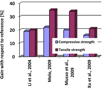
studies, cement composites incorporating CNTs in the amount of 0.3 to 0.5 % of the mass of binder show 19-34 % better tensile strength to the reference specimens (LI et al., 2004a;
MELO, 2009; MUSSO et al., 2009; XU et al., 2009). Figure 1.1 shows a comparison of some
published results on the compressive and tensile strength of CNT/cement-based composites. The gains presented are very modest in comparison to the potential of individual CNTs’
mechanical properties, but it can be foreseen, that if the issues of dispersing nanotubes in the matrix and assuring strong bond between CNTs and cement particles are solved, the results should be much more favorable. In addition to better strength, characteristics such as shrinkage and ductility are expected to show better performance, and the appearance and propagation of micro-cracks could be controlled. These enhancements besides having an impact on the structural performance of cement-based materials would also allow the concrete industry become more sustainable. The desired characteristics would provide significantly longer service life of concrete structures. Less and smaller cracks can also reduce corrosive agents to penetrate into the concrete and consequently damage the steel rebars.
Figure 1.1– Comparison of the gains for the compressive and tensile strength of CNT-cement based composites
Compared to most of the investigations in the literature, which involve the physical mixture of nanotubes and cement paste or mortar, the in-situ synthesis of these particles can resolve many of the dispersion and bonding problems. The research group based at the Nanomaterials Laboratory of UFMG developed a method to produce nano-structured clinker with in-situ synthesis of CNTs (LADEIRA et al., 2008). This technique involves industrial
4
1.3
Objective
The primary objective of this research project is to create a viable method of producing CNT reinforced cement matrices through in-situ chemical vapor deposition (CVD) synthesis
of multiwalled carbon nanotubes (MWCNTs) on clinker particles or other Portland cement-compatible materials. The in-situ synthesis is expected to radically improve the dispersion and
the bond between nanotubes and the binding material. Also continuous process production can be more efficient due to the removal of startup conditions in batch processes.
The study covers the whole process from CNT synthesis by CVD to the determination of mechanical properties of CNT-reinforced cement test specimens. There is an important focus on the development of an economically viable production process including CNT synthesis. Attempts are going to be made to reduce production costs by using residual materials as catalysts and carbon source gas and optimizing the CNT yield of the process. At the same time, laboratory CNT synthesis is needed to be up-scaled in order to produce enough material to perform strength tests and to reduce production costs. Nanotube synthesis in greater amount will allow stepping toward the industrial scale production.
This doctoral work’s objective is to investigate the influences between the process
parameters and the micro- and macrostructure of CNT-reinforced cement paste, with principal focus on tensile strength. The characteristics of the new material are to be compared with standard Portland cement in order to prove its significance as a construction material.
1.4
Scope of this study
The second chapter presents the literature review with results about cement hydration and nanostructure of cement hydration products, information on the synthesis of carbon nanotubes and their main characteristics. Test results of Portland cement composites are presented next. Finally the current state-of-art of composites prepared with cement and carbon nanotubes is reviewed in details.
The materials and methods involved during the preparation and testing of mortars containing the nano-structured cement are presented in the fourth chapter. The results of these tests are also described and analyzed.
The conclusion of the investigations is described in chapter five. Some propositions are made concerning future research.
6
2
L
ITERATURE REVIEW
2.1
Portland cement
2.1.1 Production
The origin of Portland cement (PC) is linked to Louis Vicat, a French engineer who published a work on the calcination of limestone and clays that makes a material that hardens after mixing with water (VICAT, 1818). However, it was after the patent of Joseph Aspdin, a British bricklayer, in 1824, that Portland cement got his name (of the Portland peninsula from where the prime materials were extracted).
Portland cement is the product of the heating of limestone, clays and other corrective minerals (ex. iron ore or bauxite) to approximately 1400 °C sintering temperature in a cement kiln. First all ingredients are dosed in the correct composition and ground. The resulting powder is called raw mixture. This raw mixture is then heated progressively first in cyclones using residual heat, then in the cement kiln. In the first phase of the clinker formation process free water evaporates at 100 °C. At 340 °C dolomite decomposes to MgO and CO2:
. (2.1)1
After further heating, at 800-900 °C calcium carbonate is decomposed following the equation:
. (2.2)2
Most of the decarbonation process occurs before the material enters the cement kiln. At temperatures over 550 °C clay minerals lose their combined water and form tricalcium aluminate (cement chemist notation C3A) and tetracalcium aluminoferrite (C4AF) with free
CaO. At 900 °C belite (dicalcium silicate, C2S) phase begins to form catalyzed by present Al
and Fe:
. (2.3)3
At 1250-1280 °C part of the material melts (this phenomenon is called sintering) that helps chemical reactions occur. When the material reaches 1400-1450 °C alite (tricalcium silicate, C3S) phase forms:
. (2.4)4
During the cooling process, part of the C3S phase decomposes in C2S liberating free
CaO, in function of the speed of cooling. If the cooling is too slow, a greater part of C3S
decomposes which results in a lower quality cement. The cooled material agglomerates in nodules of approximately 5 to 25 mm. The obtained clinker is then ground together with gypsum to adjust cement setting time and quality. Blast furnace slag and other pozzolanic materials can also be added. The different cement types and their composition are regulated in Brazil by the NBR 5732 (CP I – normal Portland cement), NBR 11578 (CP II – composite cement), NBR 5735 (CP III – slag cement), NBR 5736 (CP IV – pozzolanic cement) and NBR 5733 (CP V ARI – high initial strength cement) standards. The typical chemical composition of the Portland cement is 50-70 % C3S, 15-30 % C2S, 5-10 % C3A, 5-15 % C4AF
and 3-8 % of other additives or minerals (such as free CaO and MgO).
Cement production, especially the clinker formation process is considered to have high environmental impact. This impact includes a significant CO2 release that represents
approximately 5 % of global CO2 emission (WBCSD-IEA, 2009). This emission is composed
principally of decarbonation of limestone and cement kiln fuel combustion. There is high demand to reduce this emission. When comparing the environmental impact of reinforced
8 concrete and steel buildings, it can be seen that a reinforced concrete beam results in less air and water pollution and less energy consumption than a steel beam, even using more than the double of resources. The only parameter in which the reinforced concrete beam appears to have higher environmental impact is the greenhouse-effect gas emission (STRUBLE and GODFREY, 2004). According to Mehta (2009), the reduction of this emission could be achieved using three tools: (1) consume less concrete using innovative architectural concepts, structural design and high durability concrete, (2) consume less cement in concrete mixtures considering 56 to 90 day compressive strength instead of 28 days and using the newest generation admixtures and (3) consume less clinker in cement incorporating fly ash, blast furnace slag, rice husk ash or silica fume which ingredients does not additionally emit
CO2.On the other hand, due to high temperature and oxidative environment in cement kilns, it
is possible to incinerate some hazardous wastes effectively.
2.1.2 Cement hydration
One of the most actively researched fields of cement science is the hydration and formation of hydrated compounds. When Portland cement is mixed with water (H), many
different types of hydrated compounds will form. These compounds are mainly ettringite, monosulfate, calcium silicate hydrate and calcium hydroxide.
After the mixture with water, first gypsum (calcium sulfate) dissolves in its ionic compounds followed by the calcium and aluminate ions of C3A. This solution gets rapidly
saturated and some materials precipitate. The formation of the hydration products is a function of the composition of these dissolved materials and thus of the initial composition of the cement paste mixture. The most active C3A phase reacts with the dissolved sulfates to
form rod-like ettringite (AFt) crystals (stage 1 on Figure 2.1). This reaction is highly
exothermic.
After that the heat liberation is reduced during the so-called induction or dormant period (stage 2 on Figure 2.1). Two or three hours after the mixing with water alite (C3S) and
belite (C2S) start to react and form calcium silicate hydrate (C-S-H) and calcium hydroxide
(CH) crystals. C-S-H is often called gel. The grains react from their surface inwards and the
grain. The formation of C-S-H in this phase (stage 3 and 4 in Figure 2.1) is mainly responsible
for the strength of hydrated cement.
Figure 2.1– Evolution of heat liberation during cement hydration. Source: Bentz et al., 1994
The hydration of calcium silicates occurs following these equations (MEHTA and MONTEIRO, 1994):
; (2.5)5
. (2.6)6
It is seen, that C3S generates more CH than C2S. C3S hydrates more rapidly and thus
contributes to the early age (2-3 h to 14 days) strength; meanwhile C2S hydrates slower and
contributes to the strength after one or two weeks. Their hydration product, C-S-H forms
lamellas bonded covalently or non-covalently – by van der Waals forces or by adsorbed water on the surface – between each other. The appearance of the C-S-H is highly influenced by the C/S relation of the cement.
It is seen also, that the hydration of both types of calcium silicates liberates calcium ions which concentration will increase. Because of the relationship between the concentration of sulfate and calcium ions, and also the aluminate ions liberated by the hydrating C4AF
phase, monosulfate (AFm) will be more stable than ettringite. The calcium and aluminate ions
will interact with the still present sulfate ions and also partly with ettringite to slowly form monosulfate (POURCHET et al., 2006).
10 Calcium silicate hydrates being formed do not have a specific stoichiometric ratio and have generally poorly crystalline structure. Some 44 different natural minerals and their varieties have been already identified as possible forms for calcium silicate hydrates amongst them the most relevant ones are tobermorite, jennite and jaffeite types (RICHARDSON, 2008). The resulting type of C-S-H is influenced mostly by the initial composition of cement, but also depends on the presence of admixtures and on the curing time and conditions. The tensile brittle behavior of C-S-H is due to the inherent characteristics of its constituents.
Jennings et al. (2007) used a nanoindentation technique to identify two different types of C-S-H in cement phase by mechanical characteristics. According to the moduli measured from
several indentations two peaks, corresponding to the two – low-density and high-density – C-S-H, were clearly identified. It is not well known which parameters (cement composition, cure
conditions) are responsible for the formation of each type of C-S-H.
The general form of C-S-H is an agglomerate of nearly amorphous lamellae. Each
lamella is formed by a double layer of CaO crystals with silicate ions linked on both sides, as
shown in Figure 2.2. The space between the lamellae is filled with water and dissolved ions. Water in the hardened cement matrix is classified in four groups: (1) capillary water, that is present in the greater cavities, where the distance between the C-S-H sheets is bigger than
some tens of nanometers; (2) fisically adsorbed water on the surface of lamellae, where the distance between the sheets is in the order of some tens of nanometers; (3) interlaminar water, which participates in the link between lamellae at some nanometers distance; and (4) water of the crystals which is chemically linked to the hydration products. The loss of the capillary water has low influence on the volume of the hardened paste. The remove of the adsorbed water causes drying shrinkage or creep, if the loss of water is due to mechanical loading. The loss of interlaminar water occurs by intensive drying and results in massive volume loss of C-S-H. The water of crystals can only be removed by calcination at high temperatures and
Figure 2.2– Nature of bonds between C-S-H lamellae. Source: Ramachandran and Feldman, 1996
The position of C-S-H lamellae is aleatory with some parts linked between each other. These links may occur directly between the silicates of the lamellae, or through other molecules or ions (hidroxyl, calcium hydroxide, see Figure 2.2). The nature of these bonds is principally ionic or covalent, but can be also by hydrogen bridge or by van der Waals attraction. (PELLENQ et al., 2008)
The hardened cement paste is porous even after the most efficient compacting. This occurs because the formed crystals occupy less volume than the sum of cement and mixing water. These pores are in the region of macro-, mezo- and micro pores. The pores of the smallest diameter are capillaries between the agglomerates of C-S-H or other hydration
products.
C-S-H lamellae form particles of the size of tens of nanometers. These particles make
agglomerates of the size of microns. The set of these agglomerates form centimeter size minerals.
To enhance cohesion of C-S-H and mechanical behavior of hardened paste, Gleize
(2008) suggests two main strategies:
Control of the nanoporosity of C-S-H and the interlaminary distance, in order to assure
the continuity and uniformity of bonds;
12 It is important to know, that meanwhile standard concrete or mortar strength is achieved at 28 days, hydrated cement never stops to continue hydrating and – depending on the climatic conditions which the structure is exposed to – continues gaining strength.
The ratio of the cement’s constituents influences the strength achieved at different
ages of the concrete and other characteristics. The set time depends on the C3S/C2S ratio, with
faster setting at higher C3S contents. Higher C4AF content slows hydration. Sulfate resistant
cements contain less C3A. Another important factor on cement hydration speed is the fineness:
smaller grains are easier to hydrate. Cement hydration is a highly exothermal reaction. With higher hydration speed more heat will be generated that can damage concrete if exceeds a certain limit. Also the amount of heat liberated can cause a differential drying of the concrete structure causing cracks. The hydrated cement has pH between 12 and 13. This gives a
protection to steel reinforcing bars. If the pH lowers, the protection ceases its effects. 2.1.3 Admixtures for cement paste, mortars and concrete
Organic admixtures such as milk, blood or eggs were used already by antique Romans and also in the middle ages to enhance water resistance of concrete or for tinting. It was later discovered, that water to cement (w/c) ratio of the mix highly influences the final strength of concrete. Although the amount of water necessary to totally hydrate the cement is approximately 30 % of the cement mass (JOLICOEUR and SIMARD, 1998), the amount of mixing water used is generally higher in order to secure good workability and casting characteristics to the fresh concrete. This additional water will not compose hydrates with the cement, thus it will leave pores in the hardened matrix after evaporation. These pores are imperfections of the matrix and will be possibly the origin of cracks.
In order to reduce the amount of water used in a concrete mix, special surfactant agents as modern concrete admixtures have been developed to assure workability while reducing w/c ratio. Besides water reducing, some admixtures have effects also on other characteristics of fresh or hardened cement paste, such as retarding or acceleration of setting and hardening, air-entraining, etc. These characteristics also help to achieve a concrete/mortar/cement paste with the desired behavior at fresh or hardened state (ACI E-701, 2003).
surface of cement grains so that they will repel each other and assure more fluidity to the mix. Lignosulfonate based plasticizers can reduce the amount of water needed by approximately 5 %. They tend to entrain air and have set retarding effect due to their polysaccharide content.
Second generation water reducing admixtures were already designed to avoid such fact. They were mainly ionic (both cationic and anionic) surfactants, giving a charge to the cement particles to create repelling and dispersing effects between them. Some typical chemical compositions of these admixtures are sulfonates of (poly)naphthalene or melamine.
The newest generation of water reducing admixtures is based on polycarboxylate-ethers. They can reduce the amount of water necessary for the same consistence by up to 40 %. Their effect is based rather on steric repulsion of cement particles. The polycarboxilates are composed of a comb-like structure with a primary chain and lateral ether chains. It is the carboxylate groups of the main chain that assure adsorption to the cement particles, while the side chains provide the steric hindrance effect. The behavior of the polycarboxylate thus depends on its structure. The number of carboxylate groups and the length of the main chain affect the adsorption and the length and the number of ether side chains influence the dispersive ability (YOSHIOKA et al., 1997). The comb-like superplasticizers may have a
longer duration as the graft chains of the adsorbed molecule can remain active until the hydration products have incorporated them (FLATT and HOUST, 2001).
Since the behavior of concrete admixtures depends on various factors such as cement and aggregate type and composition, it is advisable to perform trial mixtures in order to determine the correct type and dosage of the admixture, with respect to the needed fresh state or hardened characteristics.
Flatt and Houst (2001) state that admixtures can interact with cement particles in three ways. They can be adsorbed on the cement grain surface, may be consumed by intercalation, coprecipitation or micellization forming an organo-mineral phase, or can remain in solution. Adsorption characteristics of admixtures on cement are generally related with their efficiency, but some care should be taken when performing adsorption tests. Adsorption and plasticizer efficiency measurements should be performed by saturated (high concentration) admixture solutions; otherwise the consumption of the surfactant in the organo-mineral phase will be more important. When wetting cement particles, a so-called double Stern layer is created around them. The positive Ca and Mg ions enter into solution leaving a negatively charged
14 admixture is anionic, it will thus be adsorbed in the outer Stern layer. At the same time, a cationic molecule will be adsorbed in the inner Stern layer, which is slightly more difficult, since the admixture molecule have to cross the outer layer first (ZHANG et al., 2001). The
adsorption characteristics of the same admixture on different cement mineral phases may be different, as it was demonstrated by Yoshioka et al. (2002).
The organo-mineral phase is composed by the admixture molecules and dissolved ions from cement. Complexes formed by sulfates and admixture consume more sulfate and thus will favor AFm formation rather than AFt in the hardened paste. Complexes formed by
admixture molecules and calcium or C-S-H have also been observed (UCHIKAWA et al.,
1995; FLATT and HOUST, 2001).
Puertas et al. (2005) found that water reducing or superplasticizer admixtures
generally cause delay in early hydration and retardation of setting. This phenomenon may be explained by the competitiveness between admixture molecules and dissolved ions of cement particles to form hydration products or organo-mineral phase. Admixture molecules adsorbed to the cement particle surface block the way for ions of the cement particle to enter in solution. The presence of admixtures during cement hydration also limits the dissolvable ion quantity as the mixing water already contains a dissolved phase (the admixture) and becomes saturated more rapidly. At early hydration ages a difference in the pore structure of hardened paste was observed by Puertas et al. (2005) when applying admixtures, but no difference was
shown in the mineralogical composition and morphology of hydration products.
2.2
Carbon nanotubes
Carbon nanotubes (CNTs) are a special form of carbon. They were already used –
development of new CNT based materials and devices are the costs of production, purification and functionalization. Also, there is little experience in the up-scaling production from laboratorial size to industrial.
CNTs are long, rolled graphene sheets. According to the number of sheets, single walled carbon nanotubes (only one sheet, SWCNTs) and multi walled carbon nanotubes (more than one sheet, MWCNTs) can be differentiated. The number of walls can be up to 40 or 50. The chirality – the direction in which the grapheme sheet is rolled – is a characteristic of every single nanotube wall. According to the chirality of the SWCNTs, they can be classified as armchair, zig-zag or chiral structure (Figure 2.3). Chirality is characterized by a vector (n,m), where n and m are the unit vectors on an imaginary infinite grapheme sheet.
These structural differences may result in different mechanical, electric or thermal behavior. It remains still a challenge to have a total control on CNT chirality during the synthesis (especially for MWCNTs).Nowadays there are only some theoretical studies on the comparison of the mechanical properties of SWCNTs with different chiralities. It is supposed that zig-zag type CNTs have slightly lower tensile strength than armchair structure CNTs because of the parallel position of some of the covalent links between carbon atoms to the axis of the nanotube and loading (NATSUKI et al., 2004; RANJBARTOREH and WANG,
2010).
Figure 2.3– Different CNT chiralities according to the direction of rolling of the graphene sheet with possible chirality vector coordinates. Y axis is the direction of the CNT axis and X axis is the direction in which the
16 In practice, CNT structures are not perfect: they show defects and deformations. These defects show up where a hexagon in the graphene sheet is replaced by a pentagon or heptagon, or can be a result of the presence of impurities. Also, different materials and particles can be built inside the CNT. These points of defect bring other important characteristics to CNTs and thus are often introduced in a controlled way. These imperfections and functional groups linked to them are an important factor in functionalizing (preparing to use) CNTs, because pristine nanotubes are hydrophobic, have low reactivity and tend to stay together due to the attraction of van der Waals forces.
The so-called carbon nanofibers (CNFs) are different from conventional carbon fibers. Nanofibers have significantly smaller diameter (10-200 nm in comparison with fiber’s 7-15
μm diameter) and have a different, tube-like structure. CNFs are also different from CNTs, which have even smaller diameter and are formed by ordered graphene layers along with the axis; while the orientation of the layers of a CNF is at an angle to the axis (Figure 2.4).
Figure 2.4– Schematic comparison of structure and diameter of carbon nanotubes, nanofibers and fibers. Based on Mori and Suzuki (2010)
2.2.1 Synthesis
Figure 2.5– Growth mechanisms of CNTs. Source: Daenen et al. (2003)
The main CNT synthesis methods used are arc discharge, laser ablation, flame
synthesis and chemical vapor deposition (CVD). Even in a simple paraffin wax candle’s
flame CNT formation was observed (LI and HSIEH, 2007), which demonstrates that any combustion of carbonaceous material may synthesize CNTs. The soot in the air we breathe in contemporary urban ambiance can contain CNTs (MURR et al., 2004) and there is some
evidence, that nanotubes were present in prehistoric atmosphere also (ESQUIVEL and MURR, 2004).
In arc discharge, carbon vapor is created between two carbon electrodes, and nanotubes form from this vapor. CNTs grown by arc discharge have high impurity but their size is highly controllable.
Laser ablation technique uses a high power laser beam to decompose a carbon feedstock (hydrocarbon gas) in its constituents in order to form CNTs. The product of laser ablation is of high purity but the method is not too productive.
The CVD is the pyrolysis of hydrocarbons at temperatures generally between 500-1000 °C over transition metal catalysts supported on a stable material (Figure 2.6), and it is proved to be a promising method for large scale production of CNTs. The product is of high purity and the technique is relatively economic. Numerous catalyst-support combinations, carbon source and carrier gas and synthesis conditions (temperature, process duration and gas flow rate) have been tested to grow CNTs. Vesselényi et al., (2001) compared the catalytic
18 catalytic activity of different support-catalyst combinations and the product morphology was compared in the work of Kathayini et al. (2004). The authors prepared the combinations of Fe, Co and Fe/Co particles as catalyst and Ca and Mg oxides, hydroxides and carbonates as
support, and these catalysts showed significant differences in the carbon yield and morphology using the same synthesis parameters. They successfully identified some support-catalyst combinations that proved to be efficient in CNT synthesis. Recently, Nasibulin et al.
(2009) and Mudimela et al. (2009) used Portland cement clinker and silica fume, respectively,
to grow CNTs and carbon nanofibres (CNFs). Yasui et al. (2009) and Dunens et al. (2009)
reported independently the growth of MWCNTs and CNFs on fly ash with or without further iron addition.
Figure 2.6– Schematic view of a CVD reactor. The gases used in this case are argon and acetylene.
An important value to evaluate CNT growth efficiency of a catalyst-support combination at given synthesis conditions is carbon yield (Y):
, (2.7)7
where w1 is the catalyst’s initial weight, w2 is the weight loss of the catalyst at the reaction
temperature and w3 is the total weight of the carbon deposit and the catalyst (COUTEAU et
al., 2003).
Other important properties of CNTs are size, aspect ratio, number of walls and morphology. These properties are mainly influenced by catalyst preparation and catalyst particle size (RÜMMELI et al., 2007). The size of the catalyst crystallite has a great influence
on the diameter of the nanotube to be grown (KHASSIN et al., 1997). Theoretically any
combination of a transition metal catalyst and a support material that remains stable at the
process temperature can be used for CVD CNT synthesis, but Fe, Ni and Co are the most used
catalysts on a high surface area support.
The gases used as carrier for CVD process are mainly N2 and noble gases as Ar. The
carbon source used is mainly a hydrocarbon gas (methane, ethylene, acetylene etc.), but carbon monoxide or heavier hydrocarbons are also an alternative.
Carbon yield and product quality are dependent of catalyst type and preparation method, type and flow of gases and process temperature and time.
The price of CNTs is still high, but falling, due to the high capacity of CNT production facilities being installed. Couteau et al. (2003) developed a continuous, large scale
CNT-production CVD method using a rotary-tube oven (Figure 2.7). The application of such a continuous production line would raise significantly the production capacity and thus, reduce prices.
Figure 2.7– Rotary CVD furnace for continuous CNT synthesis. Source: Couteau et al. (2003)
2.2.2 Functionalization
20 functional groups; other methods involve the – covalent or non-covalent – attachment of a specific molecule.
Many methods and materials have been tested to functionalize CNTs. Shaffer et al.
(1998) present a method based on aqueous nitric and sulfuric acid treatment of MWCNTs to attach oxygen containing functional groups on their surface. Using FTIR spectroscopy the authors observed the presence of carboxyl groups. The so-treated nanotubes dispersed in water with ease. Datsyuk et al. (2008) compared some different CNT-functionalization
treatments. The used nanotubes were multiwalled. The compared methods were based on hydrochloric acid, nitric acid, piranha solution (a mixture of sulfuric acid and hydrogen peroxide) and ammonium and hydrogen peroxide treatments. When evaluating the aqueous dispersion, the authors found that the mentioned functionalization methods were efficient with the exception of hydrochloric acid treatment. A functionalization method based on ozone treatment in hydrogen peroxide was developed by Naeimi et al. (2009). XPS studies showed
the attachment of carboxyl groups on the MWCNTs. The ozone treatment is much milder than the above mentioned acid treatments, and so damages less the CNT structure. Furthermore, ozone can be generated and used for treatment under much simpler conditions than acids. Meanwhile, it is still able to attach carboxyl groups to CNTs, as it was found in the comparative study of Sulong et al. (2009).
The injection of ammonia during the synthesis process incorporates nitrogen atoms into the CNT structure. The alterations caused by this incorporation are bamboo-shape structure and amino functional groups on the surface of the nanotubes (MI et al., 2005; ŢIRPIGAN et al., 2007).
The above mentioned methods introduce functional groups covalently bonded to CNTs. Besides this, non-covalently bonded surfactant molecules can also change CNTs’
characteristics including better dispersion in water. Twenty-four different surfactants and polymers were tested by Moore et al. (2003) to disperse nanotubes in water. Earlier,
Bandyopadhyaya et al. (2002) achieved a good aqueous CNT dispersion using a natural
2.2.3 Mechanical characteristics
Although it is very difficult to directly measure mechanical characteristics of CNTs
such as axial and flexural strength, strain at ultimate and Young’s modulus, many tests have been performed on single CNTs to determine their mechanical characteristics. The obtained values are one of the highest among all known materials. Demczyk et al. (2002) measured
directly the tensile and flexural behavior of MWCNTs. The obtained tensile strength of 12.5 nm diameter nanotubes was 0.15 TPa. They reported also the flexural robustness of CNTs, as the nanotube was bent over itself during a flexural test in atomic force microscopy. The calculated elastic modulus was 0.91 TPa. Earlier Falvo et al. (1997) observed MWCNTs
under bending and reported the nanotubes sustaining local strain up to 16 %. Yu et al. (2000)
tested 19 MWCNTs under tensile loading and measured strengths between 11 and 63 GPa and
elastic modulus between 270 and 950 GPa. The Young’s modulus of CNTs with different structures was compared by Salvetat et al. (1999). The authors concluded, that the more
ordered the tube walls are, the higher its Young’s modulus will be. In Figure 2.8 typical modulus values are presented in the case of perfect, wavy and bamboo-like nanotube wall structure. When CNT’s are agglomerated, these properties are significantly reduced. Even though, Li et al. (2000) performed tensile tests on macroscopic ropes of roughly aligned
SWCNTs impregnated by PVC resin. The mean value of 3.6 GPa of tensile strength is similar to that of commercial carbon fibers.
Figure 2.8–Typical Young’s modulus values vs. disorder of CNT walls. Source: Salvetat et al. (1999)
22 As it was observed by Lu et al. (1996), ultrasound may cause damages on the CNTs
breaking and stripping the outermost graphitic layers. When the treatment of the nanotubes involves sonication care should be taken in order to avoid the deterioration of the nanotube structure.
2.3
Composites
2.3.1 Portland cement composites
Portland cement concrete is the second most used product in the world after water. There are two main directions in which concrete developed: (1) a compacter, less permeable concrete with the addition of fine materials and (2) the addition of fibers to enhance tensile characteristics that would affect permeability too, because of limited cracks.
In order to make concrete more resistant to climate and corrosive effects some fine aggregates were added to achieve higher density, less porosity and higher impermeability. For these purposes, materials with smaller particle size than those of the Portland cement particles can be used. As price is an important factor, many industrial by-products have been incorporated and tested in concrete to attain better performance. Many of these materials have pozzolanic effects or help the formation of cement hydration products. Nowadays fly ash, silica fume, blast furnace slag and rice husk ash are used in industrial scale to achieve a better performing concrete or simply to reduce production costs.
Blast furnace slag is a steel-making byproduct that contains mainly impurities of the produced steel. These impurities are mainly calcium and silica, the same materials that constitute Portland cement. In order to be used in conventional cement, the slag has to be ground to the fineness of cement particles. Slag cements have slower hydration speed and higher set time than conventional Portland cement.
Fly ash is produced in huge amounts in power plants during the combustion of coal. It is a fine powder containing pozzolanic materials, such as SiO2, CaO and Fe and Al oxides.
The use of fly ash in concrete leads to a higher final strength and durability at lower hydration speed.
Silica fume is today’s most used mineral admixture of high strength concrete. It
consists of amorphous SiO2 particles of high fineness and surface area. Silica fume is a
addition of silica fume up to 10 % of the binder content enhances the final strength and durability of concrete. At the same time, the small particles of silica increase water demand/reduce workability, increase pozzolanic activity, accelerate the cement hydration process and reduce setting time (CHENG-YI and FELDMAN, 1985; DE ROJAS and FRÍAS, 1996; BHANJA and SENGUPTA, 2005; ACI 234R-06, 2006).
After the combustion of rice husk, nearly 20 % of the material remains as ash. The ash is 92 to 95 % silica, lightweight, highly porous and has a very high surface area. The characteristics of concretes containing rice husk ash are similar to those which contain silica fume: higher setting speed, higher water demand, higher final strength and higher durability (HWANG and CHANDRA, 1997).
It is clearly seen that the smaller the particle size of these auxiliary materials is the better they can fill in the pores of the concrete. But it is clear too that the smaller the particle size is the more complicated will be the handling and application of these additional materials. Li et al. (2004b) studied the effect of the addition of SiO2 and Fe2O3 nanoparticles on
cement mortars. With the incorporation of these particles in the rate between 3 and 5 % of the binder content gains up to 26.0 and 27.1 % in compressive and flexural strength respectively have been achieved. This gain in strength was due to filling in pores and by the catalysis of cement hydration product formation by the nanoparticles. This fact was also analyzed in the work of Li (2004) in which tests performed on Portland cement concrete made with fly ash and nano-SiO2. The results showed higher heat liberation through the early stages of hydration
of the concrete due to the addition of SiO2 nanoparticles averaging 10 nm in size. Change in
the concrete weight during the cure was also observed: specimens containing 4 %
nano-SiO2with respect to the binder content had a significant mass gain at early ages when cured in
saturated lime solution. Qing et al. (2007) also witnessed higher compressive strength of
mortars incorporating nano-SiO2 than plain cement mortar reference. Other effects observed
were higher pozzolanic activity and higher bond strength between cement paste and aggregates.
24 mortar. He observed the best enhancement in cement mortar compressive and flexural strength with the addition of steel mill scale at the ratio of 40 % of the fine aggregate. The durability of such composites was not analyzed neither in the work of Flores-Velez and Dominguez nor in that of Al-Otaibi.
The other way to improve concrete performance is to add fiber-like materials that have high tensile strength and can bridge cracks and prevent them from opening. In fiber-reinforced concrete (FRC) steel, glass, synthetic and natural fibers are used. Typical fiber content of a FRC is between 0.1 and 3 % of the binder content. Today’s commercially used
fibers enhance a little the flexural strength of concrete: they are used mainly for cracking control and to help to achieve higher durability. Normally the flexural strength gain is not considered at the strength of the structure itself. The main reason for this is that there is not a known, reliable procedure to evaluate the efficiency of fiber dispersion, which is a key issue in the mechanical behavior of these composites. Carbon microfiber dispersion in Portland cement composites was investigated by Chung (2005). The issues of fiber dispersion and bonding between the fibers and the cement matrix were carefully analyzed. The results showed that microscopy does not give correct information about the degree of fiber dispersion. For composites with conductive fibers in a content below the percolation threshold, the electrical conductivity may indicate the degree of dispersion, as better dispersed fibers reduce the electrical resistance of the composite (Figure 2.9). To improve the dispersion
silica fume was used: the silica size is similar to the fibers’ which allow them enter between the fibers and open the bundles. This fact was confirmed by the reduction of the composite’s
resistivity. Commercially available surfactants were also employed to achieve better fiber dispersion. The addition of polymer dispersants resulted in lower composite resistivity and higher tensile strength.