A R C H I V E S
o f
F O U N D R Y E N G I N E E R I N G
Published quarterly as the organ of the Foundry Commission of the Polish Academy of Sciences
ISSN (1897-3310)
Volume 7
Issue 4/2007
49 – 56
11/4
Synthesis of nanoparticeles in ductile iron
with small additions of vanadium and
niobium and its mechanical properties
E. Fra
ś
*, M. Górny, M. Blicharski, S. Dymek, E. Guzik
AGH - University of Science and Technology, Reymonta 23, 30-059 Cracow, Poland
*Corresponding author. E-mail address:
[email protected]
Received 22.06.2007; accepted in revised form 06.07.2007
Abstract
It has been shown that the heat treatment of 1095oC/640 oC type of ferritic ductile iron with small addition of 0.08% vanadium permits to obtain of the rounded VC nanoparticles with an average size of 50 nm and 0.13 volume fraction. Results of investigations of influence of small vanadium up to 0.3%, niobium up to 0.16% and nitrogen up to 58 ppm additions and heat treatment of 1080oC-24h/640 oC and 1080oC-24h/600 oC type on structure and mechanical properties (tensile strength, yields strength and elongation) of ductile iron are also presented in this work. It has been demonstrated that heat treatment and small additions of vanadium, and niobium as well as nitrogen enable to obtain material, which can be classified a EN-GJS-450-18 to EN-GJS-700-2 grade ductile iron.
Keywords: Ductile iron, Mechanical properties, Nanoparticles, Vanadium, Niobium carbides, Heat treatment.
1. Introduction
Ductile iron is a modern construction material and offers wide range of mechanical properties with simultaneous high wear resistance and dumping capacity [1]. From foundry practice result that in many cases production of ductile iron ensure fulfillment the Standard regarding tensile strength as well as elongation but not always yield strength archives required value. Investigations enabling affirm whether the foregoing problem can be resolve by means of small additions of vanadium, niobium and nitrogen and heat treatment are the aim of this work.
2. Methodology
Base iron was obtained in an electric induction furnace of medium frequency and with 15 kg capacity. The raw materials
were pig iron, steel scrap, Fe-75%Si, Fe-80%V and Fe-80%Nb and Fe-80%Mn-8%N. The metal was preheated at 1500 oC and then poured into sand mould to get normalized Y-shaped castings. Spheroidizing and inoculation process was made in gating system using Fe-Si-5%Mg alloy, and Foundrysil inoculant containing 0,5 % Ce in amounts 1,0 % and 0,8 % with relation to bath weight, respectively. One of the purpose of our research is to develop a method of nanoparticles synthesis in ferritic matrix of ductile cast iron, which are supposed to increase its strength without affecting notably its ductility.
mechanical grinding and polishing. Back scattered electrons (BSE) were utilized in SEM in order to reveal difference in chemical compositions of microcomponents present in particular samples. The SEM investigations were used to reveal the distribution of graphite and other big particles. Transmission electron microscopy (TEM), on the other hand, was applied for examination of nanosized secondary precipitates, i.e. vanadium or niobium carbides and/or nitrides (or carbonitrides). The thin foil technique was implemented for this purpose. The 3 mm disks were ground down on sand papers and then dimpled to about 0.1 mm thickness. Afterwards the disks were further thinned in an ion mill until a perforation had appeared. The TEM investigation was carried out by means of a JEOL 2010 ARP analytical scanning transmission electron microscope operating at acceleration voltage of 200 kV. Imaging was performed by conventional transmission mode while for chemical analysis (X-ray Energy Dispersive Spectroscopy - EDS) the nanoprobe mode was utilized. The nanoprobe mode enabled to obtain electron probes approaching a few nanometers in diameter (practically about 10 nm because at smaller electron probes the number of X-ray counts is usually too low for analysis). The EDS analysis was performed by Link system attached to the microscope. The Oxford-Link system was equipped with Si(Li) detector. This system detects all elements down to boron. In order to examine the crystallography of precipitates the Selected Area Diffraction (SAD) patterns analysis was also performed.
In the second and third stages of investigations a group of castings were austenitized at 1080 oC for 24, 50 and 100 hours followed by quick cooling to the temperature of 640 and 600 oC followed by cooling them together with furnace to ambient temperature. From castings samples with measurement diameter of 8 mm for mechanical tests were taken. Strength indicators of obtained ductile iron were: tensile strength Rm, yield strength R0,2 and
elongation A, which were determined using testing machine of INSTRON type.
3. Results
3.1 The first stage of investigation
Soaking at 1095oC for 100 h and ageing at 640 oC of cast iron
containing: C = 3.25%, Si = 3.0%, %, Mn = 0.13%, P = 0.024%. S = 0.013%, V = 0.08%, Mg = 0.04 %. gives ferritic matrix of
ductile iron (Fig.1) Examination of carbon replicas permitted the small precipitates to reveal (Fig. 2a,b). EDS analysis (Fig.2d) showed that vanadium was the main constituent element inthese particles. The carbon content was not analyzed since a strong C peak from carbon support film overwhelmed the intensity coming from carbon tied to vanadium. The particle size fell into the range 10 – 100 nm with an average of 50 nm. The particles had usually rounded shape (Fig.2b). SADP (Fig. 2e) analysis showed that all V-rich particles exhibited f.c.c. crystal structure and thus were identified as VC-type carbide. The lattice parameter calculated from SAD pattern was 416 pm and was very close to that one cited in literature [2].
Fig.1. Ferritic structure of cast iron ; 500x
Thin foil examination confirmed results obtained from replicas. Predominant dispersed particles were identified by EDS and SADP as vanadium carbides. Many of them were found on dislocations (Fig. 2c). This results can be explained as follow. During cooling the samples to the temperatures of austenite → ferrite transformation, the austenite become oversaturated with carbon and vanadium. A part of excessive carbon diffuses to graphite nodule increasing its diameter, and remaining part of carbon, together with solute vanadium, precipitate as vanadium-rich carbides.
It worth also mention that the same heat treatment applied to samples containig niobium (C = 3.51%, Si = 1.97%Si, Nb = 0.052%) or nitrogen and vanadium (C = 3.45%, Si = 2.01%Si, V=0.071% and N = 58 ppm) as well as nitrogen and niobium (C = 3.58%, Si = 2.05%Si, Nb = 0.064% and N = 32 ppm) did not produce such precipitates.
In general, on base investigation of mechanical properties of the samples from I group it can be stated that effect of VC nanoparticles on mechanical properties is rather small with tendency to increase of the yield strength R0,2 because the volume
fraction of this nanoparticles is small aprox. 0.13.
a) b) c) d) e)
The another important finding revealed by TEM was the presence of extremely small precipitates which occurred in all examined areas (Fig. 3a). The precipitates, with a diameter on the order of a few nm, gave rise to the typical type of contrast characteristic for large strain fields. The precipitates have a crystalline nature since the they showed the contrast only at certain specimen positions (specimen tilt angle) and produced some extra spots on SAD patterns (Fig. 3b). These relatively strong extra spots along with strain field contrast throughout the samples suggests fairly large volume fraction of these precipitates as well as their coherency with iron matrix. The diffuse extra spots on some diffration patterns and their proximity to the central spot may point to short ordered character of these precipitates. Though the data collected from the TEM investigation turned out to be not sufficient for identification of these precipitates, however, the occurrence of such precipitates was associated with Si content: the higher Si content the more distinct contrast in the TEM images and stronger extra spots on diffraction patterns. This observation was verified by examination of samples containing 2 to and 4.5% of Si. It can be concluded that the stronger is extra spots on diffraction patterns the higher is Rm and Ro.2 and lower elongation A
(Table 1)
a)
b)
Fig. 3. Extremely small precipitates(a) and diffuse extra spots on some diffration patterns(b)
The sample containing 4.5% Si featured the well-defined dispersoid (Fig.3a) while in samples containing less than 3% Si the dispersoid was hardly visible.
Table 1.
Chemical composition and mechanical properties of ductile iron Mechanical properties Nr of melt Silicon
content, % Rm Rm,0.2 A
W1/Si2 2,00 420 262 23
W1/Si3 3,06 479 376 12,3
W2/Si4.5 4,50 616 553 5,2
3.2 The second stage of investigations.
Chemical composition and the mechanical properties of base and heat treated ductile iron are given in Tables 2 and 3. Table 4 gives the regression equations between vanadium content and tensile strength, Rm, yield strength, Rp,0,2 and elongation, A for the base
and heat treated ductile iron.
Fig.4. Influence of vanadium and heat treatment (24 h austenitizing) on mechanical properties of ductile iron, curves: - 1
as cast, 2 and 3 after heat treatment 1080oC/640 oC and 1080 oC /600 oC, respectively Plots of these equation are shown in figures 4 and 5, where regions of ductile iron from 350-22 grade up to EN-GJS-800-2 grade, according to PN-EN 1562 (Feb., 2000) are shown. increases of the tensile strength.
450-10 grade but simultaneously shows higher yield strength Rp,0,2, which are typical for higher grade of 450-10 grade but
Table 2.
Chemical composition and mechanical properties of ductile iron Chemical composition,% As cast
1080/640 austenitizing
24 h
1080/640 austenitizing
50 h
1080/640 austenitizing
100 h
1080/600 austenitizing
24 h Nr
C Si V Rm R0.2 A Rm R0.2 A Rm R0.2 A Rm R0.2 A Rm R0.2 A
W1 3.56 2.00 0.011 420 262 23 400 275 24 - - - 410 287 20,8 408 285 20,3 W2 3.77 2.22 0.040 443 292 20 433 310 20 406 302 12,2 433 328 15,2 421 297 15,7 W3 3.24 1.98 0.081 455 297 20 432 303 16 421 316 18,7 430 314 15,7 438 305 12.8 W4 3.45 2.02 0.123 470 285 17 448 318 20 445 325 16,7 471 344 15,2 479 357 9,9 W5 3.45 2.09 0.151 499 310 17 466 348 16 461 350 14,2 508 375 13,2 492 368 12,1 W6 3.62 1.98 0.024 424 271 21 399 271 20 399 279 22,7 420 296 14,4 394 274 21.4 W7 3.63 2.03 0.025 421 275 22 400 275 21 403 284 23,9 421 298 14,1 - - - W8 3,67 2,24 0,005 429 281 21 423 298 21.3 411 292 22,5 429 312 19,4 419 298 20,8 W9 3,65 2,25 0,029 440 308 20 432 316 18.3 428 313 16,8 506 368 14,1 442 319 16.8 W10 3,58 2,08 0,044 445 307 19 446 323 18,0 445 319 18,3 463 338 17,9 459 354 14,17 W11 3,34 2,18 0,066 483 339 18 474 352 17.8 468 341 16,3 504 372 12,9 477 351 16.6 W12 3,52 2,15 0,177 632 440 11 513 376 13.3 501 381 7,7 505 398 10,4 523 382 11,6 W13 3,24 2,00 0,151 589 431 10 514 385 13.1 512 398 10,7 546 412 9,6 516 409 - W14 3,07 2,20 0,241 657 451 6 528 405 10,8 555 439 13,2 548 413 9,4 559 437 10.6 W15 3,29 2,25 0,305 687 509 4 542 407 13,6 528 418 9,7 553 418 9,2 600 441 9,0 Mn ≈ 0,1%; P≈ 0,03%;S = 0,005÷0,01%; Mg = 0,03÷0,05%
Table 3.
Chemical composition and mechanical properties of ductile iron
Chemical composition,% As cast 1080/640 austenitizing 24 h
1080/600 austenitizing 24 h Nr wytopu
C Si Nb Rm R0.2 A Rm R02 A Rm R0.2 A
Nb1 3,75 1,92 0.003 402 267 25 398 272 22 394 269 15.6 Nb2 3,63 2,06 0.007 416 267 23 406 277 24 408 281 21.8 Nb3 3,71 2,02 0.016 418 268 21 402 276 22 397 274 17,4 Nb4 3,70 2,04 0.021 416 269 23 400 277 21 401 283 21.3 Nb5 3,63 2,10 0.038 426 272 23 405 284 18 407 281 19,2 Nb6 3,66 1,85 0,044 404 268 23 405 280 22 369 272 20.5 Nb7 3,60 1,95 0,021 412 276 23 416 290 14,4 395 280 17,3 Nb8 3,58 2,05 0,062 414 277 23 412 288 24.8 398 271 - Nb9 3,89 1,95 0,053 433 298 19 403 287 17.3 417 292 24,6 Nb10 3,75 2,10 0,048 421 298 22 423 301 16.3 414 284 22,4 Nb11 3,56 1,95 0,053 428 292 13 416 292 19.5 400 269 20,9 Nb12 3,46 2,20 0,006 420 292 16 428 301 23.8 416 292 18,6 Nb13 3,23 2,25 0,123 488 338 23 434 308 20,5 431 304 17,1 Nb14 3,53 2,10 0,16 445 304 23 406 285 20,0 407 282 21.0 Mn ≈ 0.01%, P = 0.025÷0.03; S= 0.005÷0.01; Mg = 0.032÷0.06
In general, it can be stated that increase of vanadium content in ductile iron cause increase of Rm and the yield strength, Rp,0,2
while the elongation, A- decreases what is connected with decreases of ferrite volume fraction (fig.6).
Interesting results were obtained for heat treated at 1080oC/640 oC of ductile iron. For example ductile iron with 0.10 to 0.15 2 % V fulfill requirements concerning tensile strength Rm destined for
ductile iron of EN-GJS-, which are typical for higher grade of ductile iron that is EN-GJS-500-7 and higher elongation, A typical for EN-GJS-400-15 grade. In case of ductile iron with V about 0.2 % it is obtained from a viewpoint: Rm, - ductile iron of
EN-GJS-500-7 grade, A - ductile iron with higher grade that is
EN-GJS-450-10 and R0,2 - ductile iron with higher grade that is
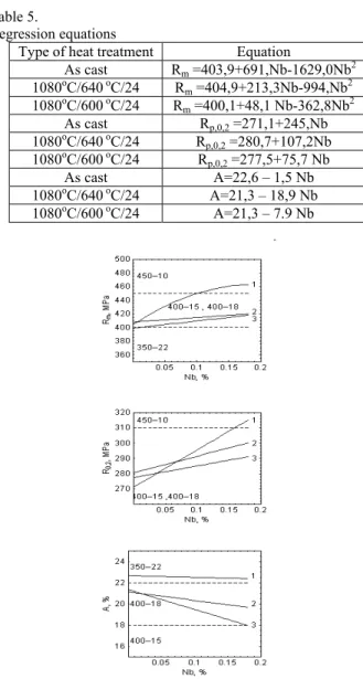
EN-GJS-600-3. Table 5 gives regression equations between niobium content and tensile strength Rm, yield strength Rp,0,2 and
Fig.5. Influence of vanadium and heat treatment (1080oC/640 oC ) on mechanical properties of ductile iron, curves: 1 - as cast, 2 - 24 h, 3 - 50 h, 4 - 100 h austenitizing
Fig.6. Influence of vanadium on ferrite volume fraction (base ductile iron)
Table 4. Regression equations Type of heat
treatment
Equation
As cast Rm =417,9+901,7V-29521V2
1080oC/640 oC/24 Rm =402,9+677,6 V-686,8V2
1080oC/640 oC/50 Rm =396,6+700,6 V-691,3V 2
1080oC/640 oC/100 Rm =418,8+739,9 V-943,2V2
1080 oC /600 oC/24 Rm =400,6+796,4 V-713,0,3V2
As cast Rp,0,2 =270,1+532,8 V-943,1 V2
1080oC/640 oC/24 Rp,0,2 =279,4+661,3 V-731,3 V 2
1080oC/640 oC/50 Rp,0,2 =278,9+708,1 V-651,5 V2
1080oC/640 oC/100 Rp,0,2 =295,1+764,1 V-1159,3 V2
1080 oC /600 oC/24 Rp,0,2 =284,3+755,8 V-713,0 V 2
As cast A=22,7 – 63,5 V 1080oC/640 oC/24 A=20,8 – 34,1 V 1080oC/640 oC/50 A=20,3 – 41,8 V 1080oC/640 oC/100 A=17,1 – 30,9 V 1080 oC /600 oC/24 A=18,5 – 38,2 V
Table 5.
Regression equations
Type of heat treatment Equation
As cast Rm =403,9+691,Nb-1629,0Nb2
1080oC/640 oC/24 Rm =404,9+213,3Nb-994,Nb2
1080oC/600 oC/24 Rm =400,1+48,1 Nb-362,8Nb 2
As cast Rp,0,2 =271,1+245,Nb
1080oC/640 oC/24 Rp,0,2 =280,7+107,2Nb
1080oC/600 oC/24 Rp,0,2 =277,5+75,7 Nb
As cast A=22,6 – 1,5 Nb 1080oC/640 oC/24 A=21,3 – 18,9 Nb 1080oC/600 oC/24 A=21,3 – 7.9 Nb
Fig.7. Influence of niobium and heat treatment on changes of mechanical properties of ductile iron, curves: 1 - as cast, 2 and 3
after heat treatment 1080oC/640 oC and 1080 oC/600 oC, respectively
As it was mentioned, in this case nanoparticles are absent and in consequence results are not such interesting as in case ductile iron with vanadium. Tables 6 and 7 give the regression equations between vanadium or niobium content and increments of the tensile strength, ∆Rm, of the yield strength, ∆Rp,0,2 and decrements
of the elongation, ∆A for the base and heat treated ductile iron. Plots of these equations are shown in figures 8 to 10. From Figs. 8 and 9 results that as vanadium content increase the increments of
∆Rp,0, are higher then the increments of ∆Rm but simultaneously at
lower of the decrements of elonagations, ∆A. Effect of niobium and heat treatment on increments of ∆Rm and ∆Rp,0 and
decrements of ∆A is shown in Fig. 10. In this case the increments of ∆Rm are similar to the increments of ∆Rm however at lower
Fig.8. Influence of vanadium and heat treatment (1080oC/640 oC) on changes of the mechanical properties of ductile iron, curves:
curves: 1 - as cast, 2 and 3 after heat treatment 1080oC/640 oC and 1080 oC /600 oC, respectively
Fig.9. Influence of vanadium and heat treatment (1080oC/640 oC ) on changes of the mechanical properties of ductile iron, curves:
1 - as cast, 2 -24 h , 3 - 50 h , 4 - 100 h austenitizing
Fig.10. Influence of niobium and heat treatment (1080oC/640 oC )
on changes of the mechanical properties of ductile iron, curves: 1 - as cast, 2 and 3 after heat treatment 1080oC/640 oC and
1080 oC /600 oC, respectively Table 6.
Regression equations Type of heat
treatment Equation As cast ∆Rm = 221.2V + 72.4 V2
1080oC/640 oC/24 ∆Rm = 168.2 V – 174.4 V2
1080oC/640 oC/50 ∆Rm = 176.6V –174.3 V 2
1080oC/640 oC/100 ∆Rm = 176.7 V – 22.2 V2
1080 oC /600 oC/24 ∆Rm = 196.8V – 169.1V2
As cast ∆Rp,0,2 = 197.3 V + 349.2 V2
1080oC/640 oC/24 ∆Rp,0,2 = 236.7 V – 261.7 V 2
1080oC/640 oC/50 ∆Rp,0,2 = 253.8 V – 233.5 V2
1080oC/640 oC/100 ∆Rp,0,2 =258.9 V – 392.8 V2
1080 oC /600 oC/24 ∆Rp,0,2 = 2656.8 V– 250.8V 2
As cast ∆A =–279.7 V 1080oC/640 oC/24 ∆A = – 163.9 V 1080oC/640 oC/50 ∆A = – 206.3 V 1080oC/640 oC/100 ∆A = – 179.9 V 1080 oC /600 oC/24 ∆A =– 206.7 V Table 7.
Regression equations Type of heat
treatment Equation As cast ∆Rm =153,Nb – 403.2Nb2
1080oC/640 oC/24h ∆Rm = 6.4 Nb
1080oC/600 oC/24h ∆R
m = 26.1 Nb
As cast ∆Rp,0,2 = 90.2 Nb
1080oC/640 oC/24h ∆Rp,0,2 = 38.2 Nb
1080oC/600 oC/24h ∆Rp,0,2 = 27.2 Nb
3.3 The third stage investigations
Chemical composition and results of influence of nitrogen, vanadium and niobium on structure indicators and mechanical properties are given in Tables 8 and 9, while examples of structure are shown in Figs. 11 to 14. Nitrogen significantly decreases ferrite fraction ff in ductile iron with additions of
vanadium and to a small extent in ductile iron containing niobium (Table 9, Fig.11 and 12). From investigations also results that nitrogen cause changes of distribution character of the graphite nodule diameter. In ductile iron without nitrogen distribution of the graphite nodule diameter exhibits one maximum, while with nitrogen two maximum. Influence of nitrogen on nodule count NF
is insignificantly (Tables 8 and 9). Table 8.
Chemical composition of ductile iron No C
% Si %
V %
Nb %
N ppm V1 3,31 2,05 0,076 - - V1/30 3,24 1,98 0,081 - 32 V1/60 3,20 2,01 0,075 - 48 V2 3,34 1,98 0,121 - - V2 /30 3,25 2,06 0,129 - 27 V2 /60 3,34 2,01 0,119 - 58 Nb1 3,51 1,97 - 0,052 - Nb1/30 3,58 2,05 - 0.064 32 Nb2 3,58 1,99 - 0,160 - Nb2/30 3,53 2,10 - 0.154 28 Table 9.
Structure and mechanical properties of ductile iron No NF
mm-2
ff Rm
MPa R0,2
MPa A %
V1 760 67 455 297 20 V1/30 632 31 555 338 12 V1/60 832 25 595 370 10 V2 759 64 470 285 17 V2 /30 847 54 489 294 15
V2 /60 757 21 632 363 9
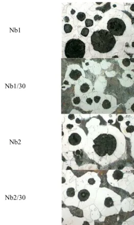
Nb1 809 65 414 277 23 Nb1/30 641 54 511 321 12 Nb2 729 68 445 304 23 Nb2/30 641 62 485 315 15 Microscopic examinations also show that in ductile iron structure a complex primary vanadium or niobium carbides are presented (Fig. 13) which are occupying below 1 % of metallographic section and smaller particles of complex vanadium carbide-nitrides (Fig.14a) and also niobium carbide-carbide-nitrides (Fig.14b) containing magnesium and silicon. In all samples it has been also affirmed presence of complex inclusions containing iron, silicon and magnesium. Mechanical tests (Table 9) show that increase in nitrogen content in ductile iron tensile strength Rm and yield
strength R0,2 increases, while elongation A decreases. It can be
judged that the main reason of such changes is decreases of ferrite fraction.
In all samples it has been also affirmed presence of complex inclusions containing iron, silicon and magnesium.
V1
V1/30
V1/60
Fig. 11. Structure of ductile iron (500x, nital etched)
Nb1
Nb1/30
Nb2
Nb2/30
Is is worth to note that ductile iron from heat no.V1/30 and V1/60 meet Rm and Rp,0,2 requiments typical for ductile iron of
EN-GJS-500-7 (according to PN-EN) grade, but with a higher elongation fulfilling ductile iron of EN-GJS-450-10 grade. Similarly from heats including niobium ductile iron fulfill GJS-400-18, EN-GJS-450-10 and EN-GJS-500-7 grade from the viewpoint of Rm
and Rp,0,2 but with higher elongation (by one class) corresponding
ductile iron of EN-GJS-350-22 and EN-GJS-400-15 standard.
a)
b)
4. Concluding remarks
1. Heat treatment of 1095oC/640 oC type of ferritic ductile iron with small addition of vanadium permits to obtain of the rounded VC nanoparticles with an average size of 50 nm and 0.13 volume fraction.
2. The same heat treatment applied to samples containig
niobium and nitrogen did not produce nanoparticles.
3. Heat treatment of 1095oC/640 oC type of ferritic ductile iron permits to obtain of the extremely small nanoparticles with diameter on the order of a few nm. These precipitates have a crystalline nature and occupies large volume fraction . 4.Heat treatment of 1080oC/640 oC and 1080oC/600 oCtype of
ductile iron with small addition of vanadium up to 0.3% enable to obtain material, which can be classified from a viewpoint of tensile strength and elongation as a EN-GJS-350-22 to EN-GJS-600-3 and EN-GJS-400-18 to 600-3, respectively, while from a viewpoint of yield strength as a ductile iron EN-GJS-400-18 to EN-GJS-700-2 that is higher grade.
Fig.13. Appearance of vanadium carbides (a) and niobium carbides (b)
a)
b)
5. Heat treatment of 1080oC/640 oC and 1080oC/600 oCtype of
ductile iron with small addition of niobium up to 0.16% enable to obtain material, which can be classified from a viewpoint of tensile strength and of yield strength as EN-GJS-450-10 to EN-GJS-400-18 and elongation as a EN-GJS-350-22 to EN-GJS-400-18.
6. Additions of nitrogen in ductile iron: changes distribution of graphite nodule diameter, essentially increases of pearlite fraction and also of tensile strength Rm as well as of yield
strength Rp,0,2 and decreases of elongation.
7. Vanadium, niobium causes formation of complex vanadium and niobium carbides and nitrogen additionally causes formation of complex carbide-nitrides particles.
Acknowledgements
This work was supported by KBN No. 3 T08B 058 28
References
[1] C. Podrzucki, Żeliwo, ZG STOP, Kraków , 1991. [2] Goldschmidt H.J., Interstitial Alloys, Butterworth, 1967. Fig.14. Appearance of carbon-nitrides particles in ductile iron