ISSN 1549-3636
© 2009 Science Publications
Corresponding Author: David Nino, Jordan University, Amman, 11942, Jordan
Separable Watermarking Technique Using the Biological Color Model
1
David Nino,
2Moussa Abdallah and
1Bassam Hammo
1
Jordan University, Amman, 11942, Jordan
2
Princess Sumaya University, Amman, 11941, Jordan
Abstract: Problem statement: The issue of having robust and fragile watermarking is still main focus for various researchers worldwide. Performance of a watermarking technique depends on how complex as well as how feasible to implement. These issues are tested using various kinds of attacks including geometry and transformation. Watermarking techniques in color images are more challenging than gray images in terms of complexity and information handling. In this study, we focused on implementation of watermarking technique in color images using the biological model.
Approach: We proposed a novel method for watermarking using spatial and the Discrete Cosine Transform (DCT) domains. The proposed method deled with colored images in the biological color model, the Hue, Saturation and Intensity (HSI). Technique was implemented and used against various colored images including the standard ones such as pepper image. The experiments were done using various attacks such as cropping, transformation and geometry. Results: The method robustness showed high accuracy in retrieval data and technique is fragile against geometric attacks.
Conclusion: Watermark security was increased by using the Hadamard transform matrix. The watermarks used were meaningful and of varying sizes and details.
Key words: HSI model, DCT transformation, watermarking, dual domain, hadamard transform
INTRODUCTION
Benefits of digital media such as efficient storage and ease of manipulation and transmission, led to the enormous growth in usage and research in this field[1]. However, digital information can be easily duplicated, forged and distributed. Hence the need for copyright protection tools has arisen. Cryptography and watermarking were suggested as tools to meet this need. But cryptography is rather costly since it needs a special hardware to be merged with it. This is why researches headed towards watermarking techniques. Digital watermarking is a way of hiding data (information) within digital media, such as audio, video and digital images. It is considered one of the various software products developed to address the growing problems in digital media[2].
In watermarking, a distinguishing piece of information (watermark) is embedded into a multimedia object (cover work) such that the watermark can be detected or extracted later to make a declaration about the object[3].
Traditionally watermarking is done by embedding a character string, in the cover work, such as the author name. Yet this does not guarantee the authenticity of the source, since the cover could be watermarked by
anyone, with any particular name, or string. Consequently the need for a newer watermark, the biometric traits of humans, such as signatures or finger prints increase the security of watermarking techniques for the purpose of authentication and proof of ownership. Furthermore watermarking techniques using biometric qualities can assure that the image was not tampered after it was signed and verifying the signature of the author, reduces the chances of a forgery[4].
be imperceptible without any visual artifacts. This type of watermarking is used to identify the owner or origin of the host image and to detect any possible unauthorized image copies. One other way of classification depends on the domain of embedding the watermark in the cover object. The watermark can be embedded in the spatial domain as in[12-15]. Or it could be in one of the transform domains such as the Discrete Cosine Transform (DCT), or the Discrete Wavelet Transform (DWT) as in[16-21].
Watermarking in the spatial domain is computationally easy to implement, but it is not robust enough to withstand common image distortions such as additive noise and filtering[22]. In order to overcome this weakness, our technique uses both the spatial and DCT domains in watermarking.
In this study, we will investigate a watermarking system in the Hue, Saturation and Intensity (HSI) color model. It is also called Hue, Saturation and Lightness (HSL). HSI is drawn as a double cone or double hexcone. It is a non-linear deformation of the RGB color cube[23]. HSI color space detaches the intensity, which is the most useful descriptor of monochromatic images and a key factor in describing color sensation, from the color-carrying information (hue and saturation) in a color image[23].
HSI color model has several advantages over the Red, Green and Blue (RGB) model. In the RGB color model, red, green and blue color components are highly correlated, therefore it is not ideal for all applications and difficult to execute some image processing algorithms. Moreover, the HSI color model makes it possible for many processing techniques, such as histogram equalization, that work only on the intensity component (page) of an image, to be easily implemented using this color model. Hence, by applying the watermark using HSI, we will reduce the complexity of the system and provide a better and more robust approach[23].
Watermarking techniques are investigated to increase the security and prove the ownership over networked computers and the World Wide Web. Information hiding techniques, watermarking in specific, are being vastly investigated since the first academic conference on this topic in 1996[24].
The technique in[25] is a block based spatial watermarking method. This method inserts watermark information using a secret key in a digital image. The process decomposes images spatially into blocks and classifies pixels in homogeneous luminance zones. This method introduces no artifacts for JPEG compression of quality factor 75%. Our method transforms the image to the frequency domain in a block wise manner, not pixel
wise. Embedding is done in the mid band frequency of the DCT block.
The term “Dual watermarking” was proposed in[3]; the duality comes from the visible and invisible watermarks embedded in the cover image in the DCT domain. This method protects both ownership and authenticity of the images. The duality proposed by our system totally differs from the one proposed in[3]. We mean by duality, both the spatial and frequency domains.
In 2004 Al-Omari[26], presented a technique that embeds a watermark in the DCT domain after truncating the DCT coefficients to the nearest integer. His system, as most of the systems provided in the literature that work in the DCT domain, neglects the decimal part of the DCT coefficients. With block size equal to 8×8, Al-Omari embeds 8 bits/block in the highest DCT coefficients in each block.
The main goal of this study is to present a novel technique to watermarking. Our dual domain technique investigates the use of the HSI color model and the DCT domain. The security and robustness are improved to withstand more attacks. The correlation factor between extracted watermarks is used to determine resemblance and accuracy of extraction. One of the main objectives our technique has is to maintain the marked image imperceptible and without any noticeable artifacts.
MATERIALS AND METHODS
Our proposed technique is a dual domain watermarking method. It uses both the spatial and the DCT domains for watermarking in the HSI color model. The embedding and extraction processes are performed on the image in its HSI color representation. Therefore, our technique depends on transforming the colored image from one representation to another, i.e., from RGB to HSI and vice versa.
The main component of the HSI color space that was mainly used is the intensity. Intensity (gray level) embodies the achromatic notion and is a key factor in describing color sensation. It is the most useful descriptor of monochromatic images, which is a measurable and interpretable quantity[23]. The intensity was used for watermarking in both the spatial and DCT domains. Hue and Saturation were used as well to embed and extract watermarks from the cover object.
Transformation of the image from the RGB color space to the HSI color space notation is done according to the following formulas:
if B G
H
360 if B G
θ ≤
=
− θ >
(
) (
)
(
) (
)(
)
1
1 2 2
1
R G R B 2
cos
R G R B G B −
− + −
θ =
− + − −
(2)
We used (1) to compute the H component of each RGB pixel. θ represents the angle measured with respect to the red axis of the HSI space. It was calculated by using (2):
(
3)
S 1 min (R,G, B)
R G B
= −
+ + (3)
1
I (R G B) 3
= + + (4)
Using (3), the saturation component was calculated and the intensity component was computed by using (4). Before applying this transform, the RGB values must be normalized to the range [0, 1]; the resulting image is also normalized to this range for the testing phase[23].
The inverse transform of the HSI, which transforms from HSI to RGB color space, is done depending on the sector in which H is located. These sectors are of 120° intervals which mean that there are three sectors[23].
The transformation from HSI to RGB is performed as follows: if the HSI values are in the interval [0, 1], H is multiplied by 360° to return the hue to its original range [0, 360°].
The first sector is the RG sector where (0°≤H<120°). In this case the equivalent RGB values are given by:
B=I(1 S)− (5)
Scos H R I 1
cos(60 H)
= +
−
(6)
G= × −3 I (R+G) (7)
The second sector is the GB sector (120°≤H<240°). Here we need to reset H to the interval [0, 1], by subtracting 120° from it as shown in (8):
H= −H 120 (8)
Depending on the new hue value that we calculated, using (8), the RGB components are:
R=I(1 S)− (9)
Scos H G I 1
cos(60 H)
= +
−
(10)
B= × −3 I (R+G) (11) The last sector is the BR sector where (240°≤H<360°). As in GB sector, we need to return it to its normal range. Here we do it by subtracting 240°:
H= −H 240 (12)
Using (12) for the H values, we calculate the RGB components as follows:
G=I(1 S)− (13)
Scos H B I 1
cos(60 H)
= +
−
(14)
R= × −3 I (R+G) (15)
The HSI color model was chosen in our technique for the increased characteristics that assist in manipulating colored images.
Watermarking in the DCT domain takes place in the HSI color model. The DCT allows an image to be broken up into different frequency bands. In this technique, the middle frequency bands are chosen for embedding since they do not represent the most important visual parts of the image[26]. Low frequency bands represent the most important visual parts in the image, therefore, embedding in such bands generates artifacts that are visible to the observer. On the other hand, embedding in the high frequency bands avoids violating the perceptible parts of the image, but makes it more vulnerable to removal when compressed or attacked.
Generally digital watermarking systems have two main stages; embedding and extraction[27].
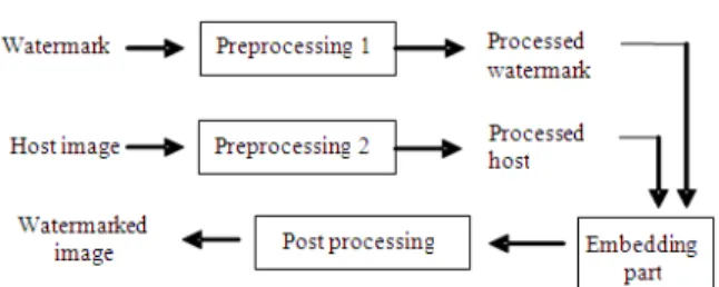
Fig. 1: Embedding stage. This figure shows a block diagram of the embedding process. It also shows that there are two different preprocessing stages, one for the watermark and the other for the host (cover) image and one post processing stage for the result (watermarked image) Our system has a two stage encoding process, one for each domain:
DCT domain embedding stage: In our technique, the embedding process is done in a specific sequence. First, we embed a watermark in the DCT domain and then we embed several watermarks in the spatial domain. We follow this sequence in embedding since the DCT domain is robust against any possible noise generated from embedding in the spatial domain.
Embedding in the DCT domain is performed after transforming the image representation to the HSI color space. The watermark is embedded in the intensity component of the image, in its DCT transform domain notation.
The DCT can be applied to the image as a whole, or it can be performed block wise. In our technique, we perform it on the image in form of blocks of 8×8 size. The block DCT transform is performed on each partition by itself, as if it is a separate image. Then the blocks are reattached together to form the resulting transformed image.
This leads to an 8×8 blocks of frequency representing the image. The DCT transform partitions the image into varying frequency bands: Low, middle and high. We have chosen a certain region from the middle-band frequency, because the High Frequency (FH) region is eliminated when applying jpeg compression. On the other hand, the Low Frequency (FL) represents most of the weight of the image, therefore, manipulating this area will cause visual impairments and loss of data. Fig. 2 shows the 8×8 DCT block regions.
Figure 3 shows our chosen region for embedding the watermark. Our region uses most of the Middle Frequency band (FM). This region differs slightly from the ordinary FM band, since it is shifted one pixel up from the FH band; to make the system more robust to compression. The region is moved one pixel closer to the FL band, to increase the importance, without affecting the image imperceptibility.
Fig. 2: 8×8 DCT block regions. The shaded area represents the middle-band frequency in which embedding is performed
Fig. 3: An 8×8 DCT block. This figure shows the 8×8 block of the DCT transform and the shaded area is the region used in our system to embed the watermark
The DCT transform used is the two-dimensional DCT. The two-dimensional DCT is just a one-dimensional DCT applied twice, once in the x direction and again in the y direction. The two dimensional DCT for an N×N Image is shown in (16):
N 1 N 1
x 0 Y 0
(2x 1)u T(u, v) (u) (v) f (x, y) cos
2N
(2x 1)v cos
2N − −
= =
π +
= α α
π +
∑ ∑
(16)
For u, v = 0, 1, 2,…,N-1. α (u) and α(v) are defined
in (17).
The values of T (u, v) are called the DCT coefficients of the image f:
1 N For u 0
(u)
2 N For u 0
=
α =
≠
(17)
N 1 N 1
u 0 v 0
(2x 1)u f (x, y) (u) (v)T(u, v) cos
2N
(2x 1)v cos
2N − −
= =
π +
= α α
π +
∑∑
(18)
For x, y = 0, 1, 2,...,N-1.
The resulting transformed image is of floating point precision; thus we will separate the integer part from the decimal part, embed the watermark in the integer part and then rejoin the two parts together. In this way we can ensure that no data loss occurs from truncation of fine details in the decimal part.
After transforming the cover image to the HSI representation and then to the DCT frequency domain, the watermark must be prepared for being embedded. This is done by applying another transform which is the Hadamard transform to the watermark.
The Hadamard transform matrix, H, can be obtained by the formulas (19 and 20) shown below:
JJ JJ 2J 2J
JJ JJ
H H
H
H H
=
− (19)
2J 2J 1 1 H
1 1 =
− (20)
Equation 19 represents a Hadamard matrix of order 2J, where J is any natural number. The matrix of the second order is given in 20; it is used as a base for larger orders. The elements of this transform take only two values; 1 and -1, hence suitable for digital image processing.
The Hadamard matrix is an invertible one. The inverse was recursively computed using (21):
1
JJ JJ
1
H H
J − =
(21)
Now that the cover image and the watermark are preprocessed, we will embed the Hadamard transformed watermark in the middle frequency band of the DCT block. The embedding will take place only in the integer part of the transformed cover image.
After this stage, the watermarked integer part is rejoined with the decimal part. The IDCT transform is applied on the resulting watermarked intensity component. It is then joined with the hue and saturation components for the rest of the embedding process to take place.
Spatial domain embedding stage: The input to this stage is the HSI transformed image, with the intensity component watermarked by using the DCT domain
stage that was mentioned earlier. Another input is the watermark itself. The watermarks used in this stage are the same as the one embedded in the DCT stage. However, in this stage, we embed four of them and without transforming them.
Embedding the watermarks in this stage is different than the conventional spatial domain techniques in many ways. First, instead of embedding one watermark, we embed four identical rotated watermarks to withstand the rotation and cropping attacks. Secondly, the watermarks are embedded in the HSI color space, not the RGB. Thirdly, each pixel of the watermark is embedded in its corresponding pixel location in the H, S and I components alternately. We embed the first pixel of a watermark in the first pixel of the hue component, the second pixel goes in the second pixel of the saturation component and the third one goes in the third pixel of the intensity component. And so on until all the pixels of the watermark are embedded. Fourthly, we embed the watermarks’ pixels in different bit locations for each component pixel.
To make the technique rotation invariant, the watermarks are embedded in the four corners of the cover image as in Fig. 4. In the top left and bottom right corners we use the bit locations 1, 2 and 3. Whereas, the bit locations 2, 3 and 4 are used for the top right and the bottom left corners. Embedding four watermarks in each corner, is done while rotating the host image a 90° counter clock wise. The first embedding goes at zero degree rotation, then the cover image is rotated 90° and the same watermark is embedded in the top left corner. This process is done four consecutive times which returns the image to its original 0° rotation.
The final step for the embedding process is to return the watermarked image to the RGB color space. We perform the transformation from HSI to RGB based on the formulas in (4, 5 and 6).
Watermark extraction (decoding) process: The input for the extraction stage is the watermarked image. The general framework for the extraction process is shown in Fig. 5.
The extraction process has a preprocessing stage. It is the reverse of the embedding stage. The extraction process happens in a specific order. Extraction from the spatial domain is performed before the DCT domain, since we need to extract from the spatial first to know if the watermarked image has been rotated. We will begin the decoding stage by obtaining the watermarked image and converting it to the HSI color space using (1-3).
The extraction process involves the following sub processes or stages.
Spatial domain decoding stage: Extracting in the spatial domain happens from each of the H, S and I color components. The bit locations used at extraction are the same locations used at embedding and in the same way.
At this stage, we extract only two out of the four watermarks which were previously embedded. We begin extracting from the top left corner of the watermarked image, then the image is rotated 90° counter clock wise and another watermark is extracted from the same place. We compare the two extracted watermarks and select one of them to determine the angle of rotation.
If the angle is 90° then the image is rotated 90° before it is sent to the DCT decoding stage, otherwise it is sent unaltered. This test is done to check for 90° rotation attack. Other 90° increments are checked in the DCT domain decoding stage.
Although we use four identical watermarks at embedding, we have only one of them at extraction. The rest are used when rotations of 90° increment occur.
DCT domain decoding stage: Extraction of the watermark from the DCT domain depends on the result given by the spatial stage, especially in the case of rotation attack.
After we extract the two watermarks of the spatial domain, we start extracting from the DCT domain.
Fig. 5: Extraction stage. This figure shows a block diagram of the extraction process. It also shows that extracted watermark, is in a processed form and that it needs to be further processed (backward processing) before it is ready to be used
As in the embedding stage, we use the 8×8 DCT block for extraction. Again, the bit locations used are the same as those used at the DCT embedding stage. After performing the DCT extraction, we get the result as a binary matrix. This matrix needs to be transformed using the inverse Hadamard transform.
Now that we have the DCT extracted watermark, we begin a test by comparing this watermark with the spatially extracted watermark. If we reach a predefined threshold value, then both watermarks are accepted. Otherwise, the watermarked image will be rotated by 180° counter clock wise and then the DCT extraction process is repeated. This is done to check for 180° and 270° rotation attacks. After this stage is performed, we will have two watermarks extracted from both the spatial and the DCT domains.
RESULTS
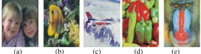
We have tested this method on a wide range of images and watermarks expanding on the tests performed in[28]. A sample set of host images is shown in Fig. 6 and some watermarks are shown in Fig. 7. Simulation results include tests performed on the different images that appear in Fig. 6 and 7. The similarity between the extracted watermarks and the original ones is presented as a correlation between them.
(a) (b) (c) (d) (e)
Fig. 6: Sample test images, all of 256 × 256 pixels; (a): Girls; it is considered to be a high density image; (b): Fish; it has a wide range of colors; (c): Plane, it is considered to be a low density image; (d): Peppers, a combination of two of the main components of the RGB system (R and G); (e): Baboon is highly filled with details and complexity
(a) (b) (c) (d) (e)
Table 1: Results of embedding a biometric signature watermark in the girls image
Correlation Correlation of of extracted extractedDCT Attack spatialwatermark watermark Normal 1.000 0.996 JPEG lossy Q* = 25 -0.008 0.996 JPEG lossy Q = 50 -0.010 0.996 JPEG lossy Q = 75 -0.007 0.996 Salt and pepper 0.05 0.749 0.996 Gaussian noise 0.05 -0.008 0.996 Rotation 90° 1.000 0.996 Rotation 180° 0.998 0.996 Rotation 270° 1.000 0.996 Rotation 90° + Gaussian noise 0.05 0.006 0.996 *Q: quality factor of the JPEG compression
(a) (b) (c) (d) (e)
(f) (g) (h) (i)
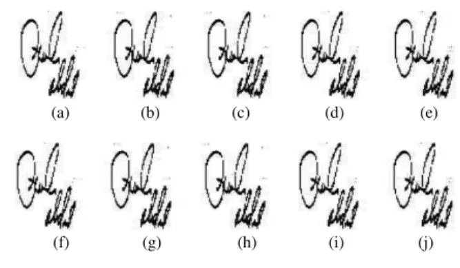
Fig. 8: The Girls image; (a): Normal test (no attack); (b): JPEG, Q = 25; (c): JPEG, Q = 50; (d): JPEG, Q = 75; (e): Salt and pepper 0.05; (f): Gaussian noise 0.05; (g): Rotation 90°; (h): Rotation 180°; (i): Rotation 270°; (i): Complex attack of rotation 90° and Gaussian noise 0.05
Table 1 shows the results of watermarking the Girls image shown in Fig. 6a, with the biometric signature shown in Fig. 7a, in the normal case and attacked by JPEG compression with 25, 50 and 75 quality factors, salt and pepper noise, Gaussian noise, rotation and a composite attack.
Images related to the tests reported in Table 1, are shown in Fig. 8. They provide a visual aid to realize the amount of attacks and distortions applied to the watermarked images. Corresponding watermarks, extracted spatially, are shown in Fig. 9. In Fig. 10, we show the extracted watermarks from the DCT domain after the attacks.
In Table 2, we demonstrate the results of watermarking the Fish image, in Fig. 6b, with the Fingerprint in Fig. 7d. The Table 2 presents the results of extracting the watermarks after applying several attacks like compression and additive noise on the watermarked image.
Table 2: Results of embedding the fingerprint watermark in the fish image
Correlation Correlation of of extracted spatial extracted DCT Attack watermark watermark Normal 0.999 1 JPEG lossy Q* = 25 0.006 1 JPEG lossy Q = 50 0.005 1 JPEG lossy Q = 75 -0.007 1 Salt and pepper 0.05 0.808 1 Gaussian noise 0.05 4.230e-04 1 Rotation 90° 0.998 1 Rotation 180° 0.998 1 Rotation 270° 0.999 1 Gaussian noise 0.05 0.003 1.000
+ rotation 180°#
Salt and pepper 0.05 -0.006 1 + rotation 180° + JPEG 75#
*Q: Quality factor of the JPEG compression; #:Complex attacks
applied consecutively to the watermarked image
(a) (b) (c) (d) (e)
(f) (g) (h) (i) (j)
Fig. 9: Watermarks that were extracted spatially from their corresponding watermarked images in Fig. 7; (a): Normal test (No attack); (b): JPEG, Q = 25; (c): JPEG, Q = 50; (d): JPEG, Q = 75; (e): Salt and pepper 0.05, (f) Gaussian noise 0.05; (g): Rotation 90°; (h): Rotation 180°; (i): Rotation 270°; (j): Complex attack of rotation 90° and Gaussian noise 0.05.
(a) (b) (c) (d) (e)
(f) (g) (h) (i) (j)
Table 3: Results of embedding the logo watermark in the plane image Correlation Correlation of of extracted spatial extracted DCT Attack watermark watermark Normal 0.999 0.994 JPEG lossy Q* = 25 -0.030 0.994 JPEG lossy Q = 50 -0.004 0.994 JPEG lossy Q = 75 -0.007 0.994 Salt and pepper 0.05 0.806 0.994 Gaussian noise 0.05 -0.009 0.994 Rotation 90° 0.998 0.994 Rotation 180° 0.998 0.994 Rotation 270° 0.999 0.994 Salt and pepper 0.05 + -0.006 0.994 JPEG lossy Q* = 25#
Salt and pepper 0.05 0.806 0.994 + rotation 90° #
*Q: Quality factor of the JPEG compression; #: Complex attacks
applied consecutively to the watermarked images
Table4:Results of performing cropping on the peppers image Correlation Correlation of of extracted spatial extracted DCT Cropping watermark watermark Center selection 0.29 0.98 Edge removal 0.94 1.00 Top left selection 1.00 0.95 Top right selection 1.00 0.99
(a) (b) (c) (d)
Fig. 11: Peppers images attacked by cropping; (a): Center selection; (b): Edge removal (1 pixel wide); (c): Top left selection; (d): Top right selection
Table 3 lists the results of applying the logo watermark that appears in Fig. 7e, to the plane image in Fig. 6c. It also provides results of applying some attacks, including a complex attack.
In addition to rotation, our technique was tested against another geometric attack, which is cropping. We tested our technique against cropping in different regions and using different watermarks. We used the watermarks in Fig. 7a, b, d and e to embed them in the Peppers image, then we performed the cropping attack in different regions of the watermarked image as Fig. 11 shows. In Fig. 12, we show the watermarks extracted spatially from their corresponding marked then cropped images in Fig. 11. Whereas Fig. 13 shows the watermarks extracted from the DCT domain from the same cropped images in Fig. 11. Table 4 presents the effect of cropping the peppers image, as shown in Fig. 11, on both the spatial and the DCT domain results. Table 4 shows the correlation between the original and extracted watermarks.
(a) (b) (c) (d)
Fig. 12: Watermarks extracted spatially from their corresponding images in Fig. 10; (a): Logo extracted from Fig. 10a; (b): Fingerprint extracted from Fig. 10b; (c): Biometric signature extracted from Fig. 10c; (d): Biometric signature extracted from Fig. 10(d)
(a) (b) (c) (d)
Fig. 13: Watermarks extracted from the DCT domain from their corresponding images in Fig. 10; (a): Logo extracted from Fig. 10a; (b): Fingerprint extracted from Fig. 10b; (c): Biometric signature extracted from Fig. 10c; (d): Biometric signature extracted from Fig. 10d. Complex attack of Rotate 90° and salt and pepper 0.05
DISCUSSION
Our proposed technique was tested on several images, each of which differs in density and colors. In Fig. 6 and 7 we present a set of host images and watermarks on which we test our technique. Those images are chosen to be of different densities, colors and details in order to observe how they affect the quality of the resulting extracted watermarks. The results in Table 1-3 are not identical, although the attacks applied are almost the same. This is due to the difference in both the host images and watermarks used. Observing these results, we find that the DCT domain produces better results than the spatial domain.
rotation (if it occurs of 90° increments), in order to extract the DCT embedded watermark correctly.
The spatial domain embedding gave acceptable accuracy in the case of salt and pepper additive noise as well. However, any Gaussian additive noise and lossy compression distorted the watermark greatly. This is due to the embedding in the least significant bits which are likely to be defeated with such attacks.
The results of the DCT domain in the third column of Table 1-3 are accurate. This is obvious from the correlation values that are almost equal to one in the DCT domain, even when complex attacks are applied. The reasons behind this, is due the fact that the DCT is not vulnerable against JPEG compression and common additive noise. Another important reason is that we embed in the mid band frequency of the DCT blocks, as shown in Fig. 3, in order to avoid modifying high weight regions of the image and to reduce the possibility of applying visual artifacts. One final reason is that we use the Hadamard transform which increases the technique’s robustness.
Although the DCT domain watermarking is not rotation invariant, our technique extracted the DCT domain watermarks fairly accurately when the rotation attack is performed. This is because of the four-watermark embedding technique which we follow in the spatial domain which helps us to inversely rotate the watermarked image until we extract the DCT domain watermark.
Different cropping regions are performed on the watermarked image as Fig. 11 shows. In these tests, different watermarks are used for embedding. As Fig. 12 shows, cropping in various regions produces accurate results in the spatial domain, except for the first region that appears in Fig. 11a. In this case of center selection, we miss the four watermarks that were embedded in the four corners. Fig. 13 shows that using the DCT domain, we extract the watermarks fairly accurately in the different cropping attacks.
CONCLUSION
In this study, we proposed a novel method for watermarking in the biological color space (HSI). We used two domains, the spatial and DCT. We used a new technique in embedding in the spatial domain. The technique has proven its robustness against several attacks, including the geometric attack of rotation and cropping. It has been shown that this method adds no visual artifacts to the watermarked image, although the watermark size is relatively large compared to the host image.
The future research is basically directed towards more robustness against other geometric attacks, such
as rescaling and rotation of different angles other than 90° increments.
REFERENCES
1. Lin, E. and E. Delp, 1999. A review of fragile image watermarks. Proceeding of the Multimedia and Security Workshop (MSW’ 99), ACM Press, USA., pp: 25-29.
http://ftp://skynet.ecn.purdue.edu/pub/dist/delp/ac m99/paper.pdf
2. Liu, R. and T. Tan, 2002. A SVD-Based watermarking scheme for protecting rightful ownership. IEEE. Trans. Multimedia, 4: 121-128. http://ieeexplore.ieee.org/iel5/6046/21237/00985560.pdf 3. Mohanty, S., K.R. Ramakrishnan and M. Kankanhalli,
1999. A DCT domain visible watermarking technique for images. University of South Florida, USA.
http://www.cse.unt.edu/~smohanty/research/ConfP apers/2002/MohantyICME2000.pdf
4. Anoop, N. and J. Anil, 2004. Multimedia document authentication using on-line signatures as watermarks. Proceeding of the SPIE-EI 2004, Security, Steganography and Watermarking of Multimedia Contents VI, (SSWMC’ 04), San Jose,
CA., pp: 18-22.
http://biometrics.cse.msu.edu/Publications/SecureB iometrics/NamboodiriJain_SignatureWatermarking _SPIE04.pdf
-5. Sahoo, T. and Christian Collberg, 2004. Software watermarking in the frequency domain: Implementation, analysis and attacks. Department of Computer Science, University of Arizona. http://citeseer.ist.psu.edu/699346.html
6. Eggers, J.J. and B. Girod, 2001. Blind watermarking applied to image authentication. Proceeding of the International Conference on Acoustics, Speech and Signal Processing, May 7-11, IEEE Xplore Press, Salt Lake City, USA., pp: 1977-1980. DOI:10.1109/ICASSP.2001.941335 7. Xie, L. and G.R. Arce, 1998. A blind wavelet
based digital signature for image authentication. Proceeding of the European Signal Processing Conference, Rhodes, Sept. 8-11, Greece, pp: 21-24. http://cat.inist.fr/?aModele=afficheN&cpsidt=1369340 8. Barni, M., F. Bartolini, V. Cappellini and A. Piva,
1998. A DCT domain system for robust image watermarking. Sign. Proc. 66: 357-372. http://portal.acm.org/citation.cfm?id=284790 9. Kundur, D. and D. Hatzinakos, 2004. Toward
robust logo watermarking using multiresolution image fusion principle. IEEE. Trans. Multimedia, 6: 185-198.
10. Mohanty, S.P., K.R. Ramakrishnan and M.S. Kankanhalli, A DCT domain visible watermarking technique for images. Technical Report, University of South Florida, USA. http://www.cse.unt.edu/~smohanty/research/ConfP apers/2002/MohantyICME2000.pdf
11. Chae, J.J. and B.S. Manjunath, 1997. A robust embedded data from wavelet coefficients. Technical Report, University of California, CA. http://vision.ece.ucsb.edu/publications/98SPIE.pdf 12. Schyndel, R.G., A.Z. Tirkel, N.R. Mee and C.F.
Osborne, 1994. A digital watermark. Proceeding of the IEEE International Conference on Image Processing, (ICIP’94), Texas, USA., pp: 86-90. http://goanna.cs.rmit.edu.au/~ronvs/papers/ICIP94.PDF 13. Wolfgang, R.B. and E.J. Delp, 1995. A watermark
for digital images. Technical Report, School of Electrical Engineering, Purdue University, USA. http://ftp://skynet.ecn.purdue.edu/pub/dist/delp/icip 96-secure/paper.pdf
14. Maity, S.P. and M.K. Kundu, 2001. Robust and blind spatial watermarking in digital image. Technical Report, Department of Electronics and
Telecommunication, India.
http://www.ee.iitb.ac.in/~icvgip/PAPERS/124.pdf 15. Nikolaidis, N.and I. Pitas, 1996. Copyright
protection of images using robust digital signatures. Proceedings of the IEEE International Conference on Acoustics, Speech and Signal Processing, May 7-10, IEEE Xplore Press, USA., pp: 2168-2171. DOI: 10.1109/ICASSP.1996.545849 16. Kundur, D. and D. Hatzinakos, 1998. Digital
watermarking using multiresolution wavelet decomposition. Proceedings of the IEEE International Conference on Acoustics, Speech and Signal Processing, May 12-15, IEEE Xplore Press, Seattle, WA., USA., pp: 2969-2972. DOI: 10.1109/ICASSP.1998.678149
17. Yang, S.H., 2003. Wavelet filter evaluation for image watermarking. Proceedings of the IEEE International Conference on Acoustics, Speech and Signal Processing, Apr. 6-10, IEEE Xplore Press,
USA., pp: 525-528. DOI:
10.1109/ICASSP.2003.1199527
18. Marusic, S., D.B. Tay, G. Deng and M. Palaniswami, 2005. Even-length biorthogonal wavelets for digital watermarking. Proceedings of the 8th IEEE International Symposium on Signal Processing and its Application, Aug. 28-31, IEEE Xplore Press,
USA., pp: 17-20.
http://ieeexplore.ieee.org/xpls/abs_all.jsp?arnumbe r=1580185
19. Inoue, H., A. Miyazaki and T. Katsura, 1999. An image watermarking method based on the wavelet transform. Proceedings of the International Conference on Image Processing, (ICIP’ 99),IEEE Xplore Press, Kobe, Japan, pp: 296-300. DOI: 10.1109/ICIP.1999.821617
20. Huang, Z.Q. and Z. Jiang, 2003. Watermarking Still images using parameterized wavelet systems. Technical Report, School of Computing and IT, University of Western Sydney, Australia. http://sprg.massey.ac.nz/ivcnz/Proceedings/IVCNZ _39.pdf
21. Hajjara, S., M. Abdallah and A. Hudaib, 2006. Image information hiding using second order biorthogonal wavelets. Proceedings of the ICIA International Conference on Information and Automation, Dec. 15-17, IEEE Xplore Press, USA., pp: 403-406. DOI: 10.1109/ICINFA.2006.374134 22. Maity, S.P. and M.K. Kundu, 2001. Robust and
blind spatial watermarking in digital image. Technical Report Department of Electronics and Telecommunication, India.
http://www.ee.iitb.ac.in/~icvgip/PAPERS/124.pdf 23. Gonzalez, R.C., R.E. Woods and R.E. Eddins,
2003. Digital Image Processing Using MATLAB. Prentice Hall, ISBN: 10: 0130085197, pp: 624. 24. Fabien, A., P. Petitcolas, Ross J. Anderson and
Markus G. Kuhn, 1998. Attacks on Copyright Marking Systems. Proceedings of the 2nd Workshop on Information Hiding, Apr. 14-17, Portland, Oregon, USA., pp: 218-238. http://portal.acm.org/citation.cfm?id=731536 25. Darmstaedter, V., J.F. Delaigle, J.J. Quisquater and
B. Macq, 1998. Low cost spatial watermarking. Technical Report.
http://www.tele.ucl.ac.be/PEOPLE/DELAIGLE/m y_publications/Computer_graphics98.pdf
26. Shoemaker, C., 2002. Hidden bits: A survey of techniques for digital watermarking. Independent
study EER-290, Prof Rudko.
http://www.vu.union.edu/~shoemakc/watermarking /watermarking.html
27. Mohanty P. Saraju, 1999. Digital watermarking: A tutorial review.
http://www.cse.unt.edu/~smohanty/research/OtherP ublications/MohantyWatermarkingSurvey1999.pdf 28. Nino, D., M. Abdallah and B. Hammo, 2006. Dual