S K Sinha. / International Journal of Engineering Science and Technology Vol. 2(11), 2010, 6622-6625
EFFECTS OF WIRE LAG IN WIRE
ELECTRICAL DISCHARGE
MACHINING (WEDM)
S. K. SINHA
Department of Mechanical Engg. Institute of Technology, Banaras Hindu University
Varanasi-221005, India
Abstract
WEDM is very useful wherever complex geometry with tight tolerances needs to be generated on hard materials. In view of modern and sophisticated technology readily available these days, the expectation of accuracy in WEDM is ever-increasing, and therefore, techniques for the improvement in WEDM must be developed. The main cause of inaccuracy is wire-lag, the cause and effect of which is described in the present work, along with a technique to obviate the problem in straight cutting. In a subsequent paper, a software approach (since the problem gets too complicated) for improvement of accuracy in contour cutting is described.
Keywords : EDM; WEDM; wire-lag
1. Introduction
The electrical discharge machining (EDM) process is a very popular non-conventional machining method. It removes material by a series of discrete electrical discharges, resulting in localized high temperature which melts and/or vaporizes the metal in its close vicinity. The only requirement is that both the electrode and workpiece material be electrically conductive, irrespective of hardness of the workpiece. The discharges occur between the tool (electrode) and the workpiece in a dielectric medium typically under voltage drop of 20 V. There is no physical contact between the electrode and the workpiece; hence it is possible to machine a hard material by a soft tool (electrode). WEDM works on the same principle except that the electrode is in the form of a conducting wire.
WEDM is mainly used for contour cutting, for which the workpiece is moved relative to the wire in horizontal plane. For accuracy, numerical control is used to control the relative motion between the wire and the workpiece during cutting. Since the wire also gets eroded in the cutting process, it is continuously fed between the two wire-guides (one above the workpiece and the other below it) to ensure its constant-diameter, throughout the cutting process.
Now-a-days, the emphasis in WEDM process is on the improvement of dimensional accuracy [1]. Although, in comparison with other non-conventional methods for similar applications, WEDM is characterized by its high accuracy, industry is gradually demanding even higher precision. The chief source of inaccuracy in WEDM is the inherent wire-lag [2] which is caused by flexing of wire under various forces. Though these forces are pretty small, causing practically zero cutting force on the workpiece, these do cause some deflection in the wire because the wire is very thin and long (i.e., have high slenderness ratio).
2. Description of wire-lag
For determining accuracy, the vibration and the static deflection of the wire (wire-lag) need to be studied simultaneously. Although a good number of researches have been carried out to study wire vibration [3] [4], very little study has been conducted to determine the static deflection, which is, in fact, a more important factor affecting precision in contour cutting. Research has been carried out to specially study deflection of the wire also [5].
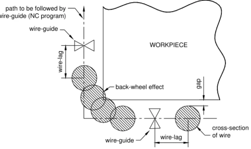
Wire-lag depends on various factors. In a given setup, it increases with increase in cutting speed. While no inaccuracy gets introduced due to wire-lag in straight cutting, this is not so when the direction of cutting changes, due to what is called “back-wheel effect” [6]. The front and back wheels of a car do not traverse the same path when the car turns towards left or right. In this analogy, the wire-guide is like front wheel, and the deflected position of the wire on the workpiece is like back wheel. While the motion is controlled for wire-guides, actual cutting lags behind it. The effect of wire-lag at an orthogonal corner has been shown in Fig. 1. In this figure, the error at the corner can be observed, which is shown magnified for clarity. While the requirement was to have a sharp corner, what we actually get is a rounded corner.
S K Sinha. / International Journal of Engineering Science and Technology Vol. 2(11), 2010, 6622-6625
wire-lag
gap
WORKPIECE
back-wheel effect
cross-section of wire wire-guide
path to be followed by wire-guide (NC program)
wire-guide
wir
e
-la
g
Fig. 1: Effect of wire-lag at an orthogonal corner
Attempts to experimentally study the deflection of the wire have been made at relatively high cutting speeds (there is no appreciable error at low cutting speeds). Also, several attempts were made to conduct a parametric study for mathematically modelling the WEDM process [7].
But to date, very little is known about how wire-lag depends on various combinations of control parameters in WEDM. Cutting speed is a very important parameter. But all what is known is that wire-lag increases with cutting speed. There is no mathematical model to calculate wire-lag for a given cutting speed. The user must continuously monitor and tune machining parameters to achieve a good machining rate with acceptable accuracy, which is not an easy task even for a skilled operator because even a slight change in cutting condition may affect accuracy. Factors affecting cutting condition include fluctuations in voltage and current, uneven distribution of dielectric, presence of debris particles in the spark-gap, random nature of discharge, and the like. Such factors are highly unpredictable and change with time, as cutting advances.
3. Effect of Wire-lag
Since the commercial introduction of wire EDM in 1969, the cutting speed almost doubled every four years due to market demand. This, however, is not without a compromise in accuracy. So, it is not practical to arbitrarily increase the cutting speed because of the associated wire-lag which is a major cause of imprecision at high cutting speeds. This does not allow taking full advantage of the advancements in NC technology for path control.
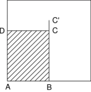
As already discussed, wire-lag does not create much problem in straight cutting. But, the moment cutting direction changes, inaccuracy creeps in. This is explained more clearly in Fig. 2, by exaggerating the error. In this example, a rectangular piece (ABCD) out of a plate is to be cut. (For simplicity, the figure has been made assuming that the radius of the wire is zero.) Though the desired shape is rectangle ABCD, after cutting along BCD, a curve is obtained at corner C, due to wire-lag. What we actually get is the shaded part. The extent of the error is the amount of wire-lag.
D C
B A
Fig. 2:A rectangular piece being cut from a plate
Hence, when cutting along a curvature, the effect of wire-lag creates a dimensional inaccuracy on the workpiece being machined. The error may be of the order of a few hundred microns, which may be unacceptable in many applications requiring high precision. The traditional cure to such a problem is reducing the machine cutting speed whenever the cutting direction changes. This, however, results in underutilization of a fast-cutting machine. Moreover, though this technique does reduce the error, but it does not eliminate it completely.
S K Sinha. / International Journal of Engineering Science and Technology Vol. 2(11), 2010, 6622-6625
4. A simple solution to the wire-lag problem
In case of orthogonal corners, the solution to this problem is pretty simple and straightforward. First, in the setup being used, one would have to accurately measure wire-lag for the chosen cutting conditions. (Either conduct an experiment or look into literature if such a data is available, though it is highly unlikely.) Then, without reducing the feedrate (i.e., movement with G01 NC-code), the wire-guide would be moved up to C’, instead of C, where CC’ is the measured amount of wire-lag. This would cut the plate up to C, due to wire-lag. Then, the wire-guide would be moved back to C at rapid rate (i.e., with G00 NC-code). Since no cutting is involved in this backward motion, there would be no wire-lag and the wire would be placed exactly at C. Thereafter, cutting motion would be started to cut along CD, without reducing the feedrate. This technique is definitely better than slow-down technique, because there is no need to reduce the feedrate. Thus, this results in accurate as well as efficient machining.
A B
C D
C'
Fig. 3: Overtravel at corner to nullify the effect of wire-lag
This technique can be used for cutting along a curve also, if the equation of the curve is known. One only needs to find out the directions of tangents (i.e., dy/dx of the curve) to the curve at closely spaced points, and locate points on these tangents which are away from the curve by wire-lag amount. The wire-guide would be made to move along these new points instead of the original curve. Due to wire-lag, machining would be done along the desired curve. This is explained in Fig. 4 with the help of a parabolic path of the form y2 = 4ax. While the parabola is described by abcdefghi (desired cutting path, or wire path with zero wire-lag), the tool is made to move along ABCDEFGHI (modified wire path), to get the desired parabola (aA, bB etc. are equal and constant wire-lag). For the plot, the equation used was
y2 = 0.25x
from which the equation of the tangent to the curve at a point (say, a) can be derived as y – y1 = 0.125(x – x1)/y1
where (x1, y1) are the coordinates of point a. Then, the coordinates of point A (x2, y2) can be found by
x2 = x1 + dcosθ1
y2 = y2 – dsinθ1
where tanθ1 is the slope (which is equal to 0.125/y1) to the curve at point a, and d is the constant wire-lag. A
series of points was generated corresponding to a large number of closely-spaced points on the parabola, and a smooth curve was passed through these points. This curve is the modified wire-path, corresponding to the chosen parabola. If the wire is programmed to move along this curve, it would actually cut the desired parabola because of wire-lag. Wire-lag would still be there, but its effect would get nullified, without compromising on cutting speed. Though a parabola was selected for this example, exactly similar method can be used for any other curve, provided its equation is known.
S K Sinha. / International Journal of Engineering Science and Technology Vol. 2(11), 2010, 6622-6625
Fig.4: Implementation of wire-overtravel method for a parabola to compensate for wire-lag
5. Conclusion
The cause and effect of wire-lag was discussed and a simple solution (overtravel method) to this problem was proposed. However, while this technique works well in the examples considered here, things get complicated when cutting is desired along a curve whose equation is not known. This is indeed a very challenging problem, the solution to which would be discussed in a subsequent paper.
References
[1] Ho, K. H., et.al. (2004), “State of art in wire-electro discharge machining,” International Journal of Machine Tool and Manufacture, 44, pp. 1247-1259.
[2] Puri, A. B., and Bhattacharya, B. (2003), “An analysis and optimization of the geometrical in accuracy due to wire lag Phenomenon in Wire-electro discharge machining,” International Journal of Machine Tool and Manufacture, 43, pp. 151-159.
[3] Puri, A. B., and Bhattacharya, B. (2003), “Modeling and analysis of wire tool vibration in wire cut electro discharge machining,” Journal of Material Processing Technology, 141, pp. 295-301.
[4] Arunachalam, C., Aulia, M., and Eubank, P. T. (2001), “Wire vibration, bowing, and breakage in wire electrical discharge machining,” Journal of Applied Physics, 89, pp. 4255-4262.
[5] Tomura, S., and Kunieda, M. (2009), “Analysis of Electromagnetic Force in wire EDM,” Precision Engineering, 33, 255-262 [6] Sanchez, J. A., et.al. (2007), “On the influence of cutting speed limitation on the accuracy of wire-electro discharge machining
corner cutting,” Journal of Material Processing Technology, 182, pp. 574-579.
[7] Han, F., Zhang, J., and Soichiro, I. (2007), “Corner error simulation of rough cutting in wire-electro discharge machining,” Journal of Precision Engineering, 31, pp.331-336.