EXPERIMENTAL INVESTIGATION ON FLOW AND HEAT TRANSFER
FOR COOLING FLUSH-MOUNTED RIBBONS IN A CHANNEL
Application of an Electrohydrodinamics Active Enhancement Method
by
Amin ALAMI NIAa* and Antonio CAMPOb
a Department of Mechanical Engineering, Azarbaijan Shahid
Madani University, Tabriz, Iran
b Department of Mechanical Engineering, University of Texas,
San Antonio, Tex., USA
Original scientific paper DOI:10.2298/TSCI130518150A
In the present study, the heat transfer enhancement of a bundle of flush-mounted ribbons placed on the floor of a rectangular duct was investigated experimental-ly. The flush-mounted ribbons act as heat sources and the cooling happens with air. The air flow was 2-D, steady, viscous, and incompressible under either lami-nar (500 ≤ ReDh≤ 2000) and turbulent (2000 ≤ ReDh 4500) conditions. The h y-drodynamics and heat transfer behavior of the air flow was studied by means of an active method with application of corona wind. The state-of-the-art of this work revolves around an experimental investigation of an electrohydrodynamics active method and heat transfer enhancement from the surfaces of the flush-mo-unted ribbons. Due to the intricacies of the required experiment, a special appa-ratus needed to be designed and constructed.
Key words: convective heat transfer, duct flow, flush-mounted ribbons, heat transfer enhancement, electrohydrodynamics, corona wind
Introduction
The majority of electronic boards are constructed with small elements that generate considerable amount of heat. Cooling of these electronic boards constitutes an essential part for their reliable operation and the main cooling systems deal with a flow of air through chan-nels. Nowadays, because of size reduction (i. e., board compaction), the cooling medium has become a vital part of the system. Optimum active cooling systems are preferred approaches for performance evaluation criteria (PEC) of the electronic boards [1, 2]. The active method with application of corona wind is well known owing to its ability to work with any external sources of energy. Corona is a visible luminous emission caused by the creation of photon and occurs in the vicinity of sharp edges where the intensity of the electric field is high. An im-portant aspect of corona discharge is the generation of corona wind, which is a gas flow in-duced by corona discharge. This phenomenon is caused by the ionization of gas molecules and formation of electrons that accelerate in strong electric fields and collide with neutral molecules, resulting in more ionization. Because the ions are heavier than electrons, they ac-celerate and drag the neighboring gas molecules. This action generates a secondary flow, known as corona wind.
––––––––––––––
The present work examines an active electrohydrodynamics (EHD) method with ap-plication of positive corona wind for the cooling of heat generating flus-mounted ribbons placed at the base of channel. This is a novel cooling approach, and to the authors’ knowledge, has not been examined earlier.
In recent work [3], experimental investigation on the heat transfer enhancement of rectangular ribs with constant heat flux located in the floor of a rectangular channel has been achieved. In this study, the behavior of air flow was studied by passive, active, and compound methods. The comparison of the results for various boundary conditions of problem was fairly agreement. In previous works [4, 5], numerical study on the heat transfer enhancement of rec-tangular ribs with constant heat flux located in the floor of a 3-D ductflow has been achieved. In this study, the effects of the arranged holes between the rectangular ribs in channels have been reported.
Fujishima et al. [6] provided analyzed the flow interaction between the primary flow and the secondary flow in the wire-duct electrostatic precipitator. They extended to incorpo-rate the alternately oriented point corona on the wire-plate type electrodes.
Ohadi et al. [7] used the wire-plate electrodes for forced convection enhancement in pipe flow. They showed that the two-wire electrode design provided a modest higher en-hancement compared to the single wire electrode design. With two electrodes, they showed that for Reynolds numbers up to 10000, it is possible to use this technique for enhancement.
Kasayapanand and Kiatsiririot [8, 9] investigated the heat transfer enhancement with the EHD technique in laminar forced convection inside a wavy channel with different wire electrode arrangements. The electric field is generated by the wire electrodes charged with DC high voltage. The mathematical modeling includes the interactions among the electric flow and temperature fields. The numerical simulation was firstly applied to the rectangular flat channel and later to wavy channel.
Kasayapanand et al. [10] investigated the effect of the electrode arrangements in a tube bank with regards to the characteristic of EHD heat transfer enhancement for low Reyn-olds numbers. The numerical modeling of the laminar forced convection includes the interac-tions among the electric field, the flow field, and the temperature field. From the numerical results, they showed that the heat transfer was enhanced by the EHD at a low Reynolds num-ber and the short distance between the wire electrodes and the tube surface.
Often times in thermal systems, invigorating the heat transfer rate cause deteriora-tion in the momentum transfer. This phenomenon is called dissimilarity. At first by placing flush mounted ribbons in the floor channel, local pressure, and momentum both drop. There-fore, for a specified inlet velocity situation, more pumping power is needed. On the other hand, due to the local effects such as disturbance and the extending of contact surface, the heat transfer increases. So it is necessary to articulate a convenient similarity between these two opposing phenomena. By using a suitable active method, secondary flow of corona wind creates in space between flush mounted ribbons and causes disturbances. In the present work, to avoid immoderate changes in the physical properties of fluid, the temperature differences between the fluid and flush mounted ribbons are constrained by applying a convenient heat flux on the flush mounted ribbons.
Experimental investigation
A fully developed air flow should be supplied before the flow enters into the test section. With regards to the dimensions of the channel, the depth to height ratio is high. Be-cause the depth effects have been ignored the channel is 2-D. The apparatus is designed to ac-commodate flow with low and large values of Reynolds numbers under laminar (500 ≤ ReDh≤ 2000) and turbulent (2000 ≤ ReDh 4500) conditions. The flow is incompressible with very small Mach numbers,M 00.3, thus any interaction effects of high voltage electric fields on the measurement of temperature are due to the eliminating side effects of applied high voltage and the accuracy of thermocouples.
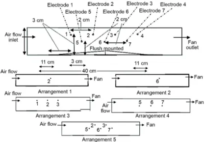
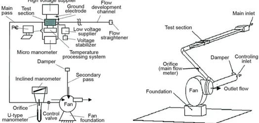
Figures 1 and 2 show the layout and the photograph of the main experimental appa-ratus, respectively. By considering the aforementioned conditions for the main experimental section, a special experimental apparatus was designed for the investigation of heat transfer enhancements involving flush mounted ribbons to fluid. For this purpose, a broad rectangular channel was used. To measure the volume rate of air flow, the orifice meter was used. The ra-tio in diameter (orifice to pipe) was adjusted to be β =d D=0.25. A special centrifugal fan was used to produce the air flow. To eliminate disturbances, the test section was located on the suction side of the fan.
Figure 1. The schematic of main apparatus
The test section was designed to be a channel with 40 cm length, 4 cm height, and 30 cm width as shown in fig. 3. Before entering the test section flows from a rectangular channel with 2 m length, the fluid proceeds with a rectangular flow-straightened screen with unit dimension of 8 mm to 20 mm. The velocity domain in the test section was 0.11 ≤ u≤ 1 m/s. The hydraulic diameter of the main channel (especially the test section) was 7.06 cm.
The fan was adjusted to operate with constant rotation. The flow rate was measured by the orifice meter under the France standard NF X 10-102. The pressure measurements should be determined with high accuracy in the two sides of the orifice. To comply with this, a U-type manometer with kerosene (S. G. = 0.865) was used.
In the test section, the ribs were electrically heated with constant heat flux. To iso-late the part attached to the floor of the channel, a fire proof fiber was used. The fire proof fi-ber is an adequate insulator of heat and electricity. The flush mounted ribbons were produced using silicon iron foil. Three flush mounted ribbons were attached on the floor of the channel. The series were connected as resistance to provide a constant heat flux of
q
w′′ =
4500 W/m
2 by means of a differential voltage transformer. The flush mounted ribbons had 3 cm in width, 30 cm in length, and 3 cm in axial spacing between them. Nine thermocouples were used for measuring the temperature of the bottom channel wall and the ribbons surface in central direc-tion of flow. The type of thermocouples is T-type with Cu-Constantan (C/CT). The geometric layout of thermocouples in the test section is shown in fig. 4 and tab. 1, where x denotes the streamwise direction from the position of the first thermocouple in the test section. The x lo-cation of the thermocouples is determined in the best lolo-cation for measuring the temperature. The position of thermocouples (x location of thermocouples) is increased on surfaces of the ribs. This position starts from the first flush mounted to thermocouple number 9. The thermo-couple number 1 is used for measuring the ambient air temperature.For temperature processing, the ADAM digital system was used. This system contains four boards for temperature measurement and a transformation board. Each measuring board re-ceives the information of thermocouples and then transfers them to the PC for processing. High voltage is applied using a high voltage supplier for the EHD wire-plate active method. Vari-ous arrangements of wire and plates were made as ground electrodes were designed between the spacing of the flush mounted ribbons. The high voltage supplier generated voltages up to Figure 3. Photograph and geometry of the test section
Figure 4. The thermocouples arrangement
Table 1. Position of the inserted thermocouples
9 8 7 6 5 4 3 2 No.
40 kV between the wire and ground electrodes. The corona phenomenon was generated be-tween electrodes with very weak current intensity. The micro-ammeter is used for current in-tensity measurements with a domain of 0-500 μA and accuracy of 10 μA. In all experimental tests, the polarity of wire electrodes is positive. The diameter of wire electrodes is 0.6 mm. The wire and ground electrodes are made from copper and aluminum, respectively. The pri-mary objective of the present work is the comparison of plain case 1 with EHD active heat transfer enhancement method. The geometry of the two cases is shown in figs. 5(a) and (b).
Figure 5. The geometry of two cases, (a) and (b)
The arrangement of electrodes with their geometric coding values is illustrated in fig. 6. The arrangements of electrodes for active method are displayed in the case 2. The wire and ground electrodes were inserted between flush mounted ribbons to enhancement of heat transfer by means of the secondary flow produced from corona wind of EHD wire-plate ac-tuator.
According to experimental results in active enhancement method, the suitable ar-rangements of wire electrodes to the ground are arar-rangements 1 and 3. In active method, the secondary flow of corona wind is from the cold main flow to the hot zone. In conclusion, two kinds of enhancement methods could be beneficial for enhancing of heat transfer from flush mounted ribbons.
The aim of this study is to investigate the heat transfer enhancement of 2-D traverse flush-mounted ribbons placed at the base of the channel.
Three parameters characterize the laminar air flow with heat transfer: – Rate of heat transfer enhancement, Et
W ref t W ref ( ) ( ) s s T T h E
h T T
− = =
− (1)
with h=qrib′′ /TW −Tref. – Consumed power ratio, Elost
lost s P E P ∆ = ∆ (2) and – PEC, ηe
t lost (PEC) e E E
η = (3)
In the sequence of eqs. (1)-(3), qrib′′ is the constant heat flux from flush mounted rib-bons to fluid flow, h – the local heat transfer coefficient, Tref – the reference temperature (inlet temperature to the test section), TW – the wall temperature in floor of test section, including sur-face of flush mounted ribbons and spacing of them, ΔP – the pressure loss, and subscript s de-notes the plain case without enhancement intervention. The
h
Re
D is Reynolds number based on the hydraulic diameter of the channel, NEHD – the EHD number and it is defined:2 2
e 0 0 i
EHD 2
f f
f f
E L bE L u L
N
v v
v
ρ ρ
= = = (4)
This parameter is similar to the
Re
hD based on velocity of electric ions ui and with the assumption of similar density for ions and neutral fluid particles. In eq. (4), ρe is the densi-ty of electric charge, ρf – the density of fluid, E0 – the electric field, b – the mobility of ions, and νf – the kinematics viscosity of fluid and then ui is defined:
0 i e0 I u q = (5)
In this equation, I0 is the electric current of corona wind, qe0 – the electric charge of one electron, which is 1.602 10⋅ −19 C. The L is the characteristic length and defined [11]:
eff h ln r C L D H r
α
=
(6)
electrode). The C/H is the ratio of space of wire and ground electrodes to channel height. The
reff/r is the ratio of effective radius of wire and ground electrodes to the radius of wire electrode and reff is defined as reff = 4C/π where C is the distance between wire and ground electrodes.
By using the active method of EHD wire-plate actuator, the corona wind as a sec-ondary flow between flush mounted ribbons is created. For analyzing this phenomenon, the new parameter of interaction of secondary flow to the main flow (strength of EHD), IEHD is introduced:
EHD
EHD 2
Re
N
I = (7)
Note that IEHD is an important parameter for the kind of active enhancement method under study here.
Results and discussion
The geometry of flush-mounted ribbons arrangements as illustrated in fig. 5 are:
L1 = L2 = 110 mm, L = 30 mm, S = 30 mm,
H = 40 mm.
As it is seen in fig. 7, the distribution of wall temperature for the two cases of plain (without EHD,
h
Re
D=
500)
and active cases (arrangement 1; 20 kV) is shown.The flush-mounted ribbons are heated with constant heat flux and therefore for comparison of EHD active method, the plain case (without EHD,
h
Re
D=
500)
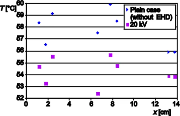
for con-fined case is base. In this figure, the effects of EHD active method on heat transfer en-hancement and the temperature reduction are shown in test section. In the space be-tween the flush-mounted ribbons, the insula-tor (incombustible fiber) has been applied and adiabatic boundary condition brings a temperature reduction. With regards to the temperature differences in fig. 7, the percent of heat transfer enhancement is of the order of 113%.In fig. 8, the rate of heat transfer enhancement for laminar forced convection
h
(Re
D=
500)
in arrangements 1 and 2 with voltages of 20 kV and 25 kV is shown. The effect of voltage on heat transfer enhance-ment depending on the wire arrangeenhance-ment was shown in the figure. In reference to thisfig-ure, the local and average heat transfer enhancement has been increased as a consequence of in-crements in voltage. The density of electric charge around of wire electrode in arrangement 1 is higher than that in arrangement 2. Therefore, arrangement 1 is better than arrangement 2.
Figure 7. Wall temperature distribution in direction of ribbon’s surface for forced convection and arrangement 1 (20 kV,
h
ReD = 500)
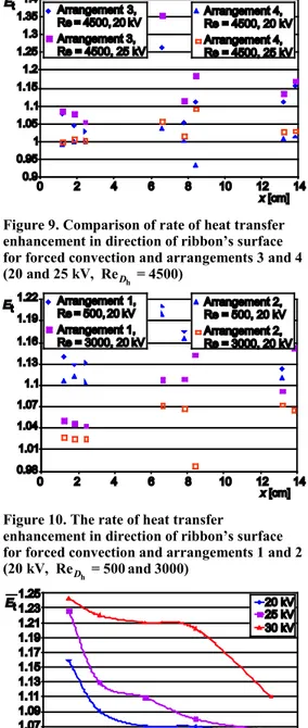
Figure 8. Comparison of rate of heat transfer enhancement in direction of ribbon’s surface for forced convection and arrangements 1 and 2 (20 and 25 kV,
h
Figure 9 displays the rate of heat transfer enhancement for laminar forced convection
h
(ReD =4500) in arrangements 3 and 4 with voltages of 20 kV and 25 kV. The effect of voltage on heat transfer enhancement depends on the wire arrangement as shown in the fig-ure. It is clear from the figure, that the local and average heat transfer enhancement was in-creased with increments in voltage. Therefore, the arrangement 3 is better than arrangement 4.
As it is seen in fig. 10, the rate of heat transfer enhancement for laminar-to-turbulent forced convection in arrangements 1 and 2 with Re = 500 and 3000 is depicted in 20 kV. The impact of Reynolds number on the heat transfer enhancement was seen in the figure. Herein, the local and average heat transfer enhancement for
h
ReD =500 is higher than their counterparts for
h
ReD =3000. For high Reynolds numbers, the main flow power is higher than the power of co-rona wind (secondary flow) in the main flow eliminating the effects of corona wind.
Figure 11 contains the average rate of heat transfer enhancement for forced convection in various Reynolds numbers with arrangement 1 for 20, 25 kV, and 30 kV. The effect of Reyn-olds number on average heat transfer enhance-ment was palpable in the figure. In numbers, the average heat transfer enhancement in
h
ReD =500is higher than those for other Reyn-olds numbers. The power of corona wind in the case of low Reynolds numbers is higher than in the case of high Reynolds numbers. Conse-quently, the corona wind in low Reynolds num-bers affects the main flow better than in situa-tions of high Reynolds numbers. Inspection of the figure reveals that the average heat transfer enhancement has been increased with elevations in voltage. At high voltages, the density of elec-tric charge and the elecelec-tric field around of wire electrodes is high. This is interpreted in terms of the corona wind, which at high voltages has a direct influence on the main flow better than those situations of low voltages.
In figs. 12 and 13, the variations of ηe with IEHD number for active method of heat transfer enhancement in
h
Re
D=
500,
2000, and 3000 are presented. As seen in figures, the effect of Reynolds number on heat transfer enhancement for active method demonstrates the Figure 9. Comparison of rate of heat transferenhancement in direction of ribbon’s surface for forced convection and arrangements 3 and 4 (20 and 25 kV,
h
ReD = 4500)
Figure 10. The rate of heat transfer
enhancement in direction of ribbon’s surface for forced convection and arrangements 1 and 2 (20 kV,
h
ReD = 500 and 3000)
opposite behavior for both low and high values. For the active method, the secondary flow can move further to the spacing between flush-mounted ribbons. The pair of figs. 12 and 13, attests that the density of electric charge around of wire electrode in arrangement 1 is higher than that in arrangement 2. As a consequence, arrangement 1 is better than arrangement 2. Switching attention to fig. 13 related to
h
Re
D=
3000,
it is detected that for positive in-teraction of the average heat transfer enhance-ment and consumed power ratio (ratio of pres-sure loss) seems to be better than whenh
Re
D=
2000.
This means that the average PEC inh
Re
D=
3000
is higher than that forh
Re
D=
2000.
The uncertainty analysis forEt,ηe,
E
t, and ηe has been carried out too. The uncertain-ty for local quantities ofEtand ηe is smaller than 8% and for average quantities ofE
tand ηe is 4-5% [12]. In fig. 14, the uncertainty analysis for various temperature points obtained from one sample of iterative tests is presented.For the case of active method, the following correlations of various Reynolds num-bers have been constructed:
(1)
h
Re
D=
500 :
Arrangement 1:42 3 28 2 15
e 10 IEHD 2 10 IEHD 8 10 IEHD 0.6003
η
= − − ⋅ − + ⋅ − +(8)
Arrangement 2:
41 3 27 2 14
e
3 10
I
EHD10
I
EHD10
I
EHD0.6535
η
= ⋅
−−
−+
−+
(9)
(2)
h
Re
D=
2000 :
Arrangement 1:39 3 26 2 13
e
8 10
I
EHD6 10
I
EHD2 10
I
EHD0.5925
η
= ⋅
−− ⋅
−+ ⋅
−+
(10) Figure 12. The PEC in direction of ribbon’s
surface for active case in
h
ReD = 500with arrangements 1 and 2
Figure 13. The PEC in direction of ribbon’s surface for active case in
h
ReD = 2000 and 3000 with arrangements 1 and 2
(3)
h
ReD =3000 : Arrangement 1:
37 3 24 2 12
e
4 10
I
EHD2 10
I
EHD2 10
I
EHD1.5437
η
= − ⋅
−+ ⋅
−− ⋅
−+
(11)
Arrangement 2:
36 3 24 2 13
e 3 10 IEHD 3 10 IEHD 5 10 IEHD 0.8814
η
= ⋅ − − ⋅ − + ⋅ − +(12)
Conclusions
This study revolved around the enhancement of heat transfer from flush-mounted ribbons in a channel flow using an active method. Two new parameters ηe and IEHD have been introduced. The parameter of ηe deals with the simultaneous effects of heat transfer en-hancement and consumed power ratio (the pressure loss ratio) on the cooling performance. The parameter IEHD embraces the interaction effects of EHD secondary flow and forced con-vection main flow together. The parameter of IEHD is ratio of EHD flow term to forced con-vection main flow term and is similar to Richardson number. The following conclusions ema-nate from the experimental study are listed.
• The power of corona wind (secondary flow) in low Reynolds flowsis higher than inhigh Reynolds flows, signifying that the corona wind in low Reynolds numbers is better than in high Reynolds numbers.
• The active method for low Reynolds numbers with laminar flows isadvantageous. The average and local heat transfer enhancement climbs up to 130% and 137%, respectively.
• For the same Reynolds numbers and wire arrangements, the heat transfer enhancement was increased with increments in voltage of the wire electrodes. At high voltages, the density of electric charge and the electric field around of wire electrodes is high. There-fore the corona wind in high voltages has been affect on main flow better than low volt-ages.
• In same Reynolds numbers and voltages of wires, the heat transfer enhancement was in-crease in arrangement 1 than other arrangements. Density of electric charge around of wire electrodes in arrangement 1 is higher than other arrangements. Therefore, the ar-rangement 1 is better than arar-rangements 2, 3, 4, and 5, respectively.
• Active method for low Reynolds numbers has higher average PEC = 0.69. The power of corona wind in low Reynoldsnumbers is higher than in high Reynolds numbers. There-fore, the corona wind in low Reynolds numbershasbeen affect on main flow better than in high Reynolds number.
• For the boundary conditions used, the correlations for the average of PEC (ηe) vs. EHD strength (IEHD) for different Reynolds numbers can beintroduced. These correlations showed that the effects of Reynoldsnumbersandarrangement on average of PEC. Densi-ty of electriccharge around of wire electrodes in arrangement 1 is higher than arrange-ment 2. Thereforethearrangement 1 is better than arrangement 2.
• The voltage of wire electrodes becomes constant after the corona wind. After corona, the voltage of wire electrodes can not changes and only electric current of wire electrodes changes. This phenomenon has been ignored in most of numerical literature works.
Nomenclature
A – area of orifice, [m2] b – mobility of ions, [m2V–1s–1] C – distance between wire and ground
electrodes, [m] D – diameter of pipe, [m] d – diameter of orifice, [m] Dh – hydraulic diameter, [m]
Et – heat transfer enhancement ratio
Elost – consumed power ratio
E0 – electric field, [Vm–1]
H – channel height, [m]
h – heat transfer coefficient, [Wm–2K–1] hs – heat transfer coefficient for plain case,
[Wm–2K–1]
I0 – electric current of corona wind, [A]
IEHD – EHD strength
L – width of flush mounted ribbon, [m], characteristic length, [m]
L1 – length of upstream region, [m]
L2 – length of downstream region, [m]
NEHD – EHD number
P – pressure, [Pa]
rib
q′′ – constant heat flux from flush mounted ribbon, [Wm–2]
qe0 – electric charge of one electron,
[Coulomb] Re – Reynolds number
ReDh – Reynolds number based on hydraulic diameter
r – radius of wire electrode, [m] reff – effective radius of wire to ground
electrode, [m]
S – separation between flush mounted ribbons, [m]
T – temperature, [K, °C] u – velocity, [ms–1]
ui – velocity of electric ions, [mgs–1]
W – width of channel, [m] x, y, z – Cartesian co-ordinates
Greek symbols
α – view angle between wire and ground electrodes
β – the ratio of orifice to pipe diameter ηe – performance evaluation criteria
υ – kinematics viscosity, [m2s–1] ρf – density of fluid, [kgm3]
ρe – density of electric charge, [kgm3]
Δ – difference
Subscripts
f – fluid
ref. – reference condition w – flush mounted ribbon wall
Superscripts
" – flux – – average
References
[1] Saini, M., Webb, R. L., Heat Rejection Limits of Air Cooled Plane Fin Heat for ComputerCooling, Pro-ceedings, 8th Intersociety Conf. on Thermal and Thermomechanical Phenomena in Electronic Systems, San Diego, Cal., USA, 2002
[2] Saini, M., Webb, R. L., Validation of Models for Air Cooled Plane Fin Heat Sinks UsedinComputer Cooling,Proceedings, 8th Intersociety Conf. on Thermal and Thermomechanical Phenomena in Elec-tronicSystems, San Diego, Cal., USA, 2002
[3] Alamgholilou, A., Esmaeilzadeh, E., Experimental Investigation on Hydrodynamics and Heat Transfer of Fluid Flow into Channel for Cooling of Rectangular Ribs by Passive and EHD Active Enhancement Methods, J. Experimental Thermal and Fluid Science, 38 (2012), Apr., pp. 61-73
[4] Alamgholilou, A., Esmaeilzadeh, E., Numerical Investigation on Effects of Secondary Flow into Duct for Cooling of the Ribs by Passive EnhancementMethod, J. Enhanced Heat Transfer, 19 (2008), 3, pp. 233-248
[5] Esmaeilzadeh, E., Alamgholilou, A., Numerical Investigation of Heat Transfer Enhancement of Rectan-gular Ribs with Constant Heat Flux Located in the Floor of a 3D DuctFlow, Asian J. AppliedSciences, 1 (2008), 4, pp. 286-303
[6] Fujishima, H., et al., Numerical Simulation of Three– dimensional EHD of Spiked-Electrode Electro-static Precipitators, IEEE, 13 (2006), 1, pp. 160-167
[7] Ohadi, M. M., et al., Heat Transfer Enhancement of Laminar and Turbulent Pipe Flowvia Corona Dis-charge, Int. Journal of Heatand Mass Transfer, 34 (1991), 3, pp. 1175-1187
[8] Kasayapanand, N., Kiatsiriroat, T., EHD enhanced heat transfer in wavy channel, International Commu-nications in Heat and Mass Transfer, 32 (2005), 6, pp. 809-821
[10]Kasayapanand, N., et al.,Effect oftheElectrode Arrangements in a Tube Bank on the Characteristic of Ectrohydrodynamic HeatTransferEnhancement: Low Reynolds Number, J. EnhancedHeat Transfer, 9 (2002), 5-6, pp.229-242
[11]Goo, J. H., Le, J. W., Stochastic Simulation of Particle Charging andCollection Characteristics for a Wire-Plate Electrostatic Precipitator of ShortLength, J. Aerosol Science, 28 (1997), 5, pp. 875-893 [12]Moffat, R. J., Describing the Uncertainties in Exp. Results, Exp. Thermal & Fluid Science, 1 (1988), 1,
pp. 3-17
![Table 1. Position of the inserted thermocouples 98 7 6 5 4 3 2 No. 13.8 13.2 8.4 7.8 6.6 2.4 1.8 1.2 X [cm]](https://thumb-eu.123doks.com/thumbv2/123dok_br/18272443.344659/4.892.150.734.812.979/table-position-inserted-thermocouples-x-cm.webp)