International Journal of Computer Networks & Communications (IJCNC) Vol.3, No.6, November 2011
DOI : 10.5121/ijcnc.2011.3606 95
M. Ali, P Pillai, Y.F.Hu and Kai Xu
School of Engineering Design and Technology
University of Bradford, UK
{m.ali28, p.pillai, y.f.hu, k.j.xu }@bradford.ac.uk
A
BSTRACTTerrestrial wireless network technologies such as UMTS, WiMax and WLAN are used to provide network access for both voice and data services. In big cities the densely populated areas like town centres, shopping centres and train stations which have coverage of multiple wireless networks, a large number of mobile users may be connected to the more common UMTS, thereby creating an unbalanced load across these wireless networks. This high load variation can be balanced by moving mobile users from heavily loaded networks to least loaded networks which involves execution of vertical handovers. Seamless vertical handovers across different wireless networks may be achieved using the IEEE 802.21 Media Independent Handover (MIH) specifications. Radio Access Technology (RAT) selection techniques aim to find the most suitable network that a mobile node should be connected to, for achieving seamless services and meeting the QoS requirements of the user. Traditional RAT selection algorithms are mainly based on the Always Best Connected (ABC) paradigm whereby the mobile nodes are always directed towards the available network which has the strongest and fastest link. This however could create a high variation among the load across the different co-located networks; which cause congestion on overloaded network and eventually increase the call blocking and call dropping probabilities. The unbalanced load situation in co-located networks also causes the poor radio resource utilization as some networks remain under loaded and some become over loaded. There is a need for the load balancing strategies to efficiently utilize the available radio resources and avoid the unwanted congestion situations on overloaded wireless networks. This paper proposes a novel network load aware RAT selection technique in heterogeneous terrestrial wireless networks to minimize the load variation in heterogeneous networks to a suitable level and describes how the MIH framework may be extended to make seamless vertical handover load conscious. The proposed strategy for load balancing consists of two different algorithms; first located in mobile user and the other at network entity such as RNC, BS or AP. The proposed method considers the network type, signal strength, data rate and network load as primary decision parameters for RAT selection process and tries to maintain the load equilibrium on all networks which have common or overlapped coverage areas. Different attributes like load distribution in all wireless networks, average end-to-end delays, jitters and average handover latencies have been observed to evaluate the effects of load balancing in considered scenarios.
K
EYWORDSInternational Journal of Computer Networks & Communications (IJCNC) Vol.3, No.6, November 2011
96
1.
I
NTRODUCTIONModern mobile devices like cell phones, PDA’s, Tablet PCs already support multiple wireless technologies like UMTS, WLAN and Bluetooth and in the very near future would also support WiMax. While most of these devices are able to scan the different available networks the user would manually select which network he or she may want to use. It is envisaged that in the near future these devices may be able to apply some complex Radio Access Technology (RAT) selection techniques to find the most suitable network. Such a RAT selection technique may need to consider various parameters like received signal strengths, errors rates, costs, user preferences, QoS requirements, etc. Such a RAT selection technique would not only play an important part when a user switches on his or her mobile device but also when the user moves around. While most of the current day mobile networks already support seamless handovers, these are restricted to handovers within the same technology, i.e. horizontal handovers. It is envisaged that to efficiently use the network services the future mobile devices shall also support handovers across different radio access technologies. This process of switching mobile devices connectivity from one technology to another type of technology is called vertical handover.The joint call admission control (JCAC) algorithm for future heterogeneous wireless networks is envisioned as user-centric. User centricity implies that user’s preferences are considered in decision making for RAT selection. However user-centric JCAC algorithms often lead to highly unbalanced networks load, which cause congestion on overloaded network and eventually increase the call blocking and call dropping probabilities. The unbalanced load situation in co-located networks also causes the poor radio resource utilization as some networks remain under loaded and some get over loaded.The load balancing strategies are required to efficiently utilize the available radio resources and avoid the unwanted congestion situationsdue to overloaded wireless networks.
Proposed solution for load balancing involves the utilization of IEEE 802.21 Media Independent handover (MIH) [1] for moving load (mobile nodes) between different wireless networks.The MIH framework defines a common interface between different link layer technologies for the support of seamless mobility between heterogeneous IEEE-802 networks and between IEEE-802 and other mobile wireless technologies. This unified interface is presented as an abstraction layer function, the Media Independent Handover Function (MIHF), for handover detection, initiation and decision via Layer 2 triggers. The MIH provides the seamless mobility to mobile nodes between heterogeneous networks using a set of services known as Media Independent Command Service (MICS), Media Independent Event Service (MIES) and Media Independent Information Service (MIIS). Brief description of IEEE 802.21 is given in the section 3.
International Journal of Computer Networks & Communications (IJCNC) Vol.3, No.6, November 2011
97
network architecture and proposed load balancing algorithms are explained in detail in Section 4. Section 5 presents the various simulation scenarios and obtained performance evaluation results and finally the conclusion is presented in the Section 6.
2.
H
ANDOVERSINH
ETEROGENEOUSN
ETWORKS2.1 Handover terminology
The handover procedure can be divided into three phases namely handover initiation, handover decision and handover execution. The first two phases (handover initiation and decision) can be comprised of any four basic schemes which are: mobile controlled handover (MCHO), network controlled handover (NCHO), mobile assisted handover (MAHO) and network assisted handover (NAHO). There can be other hybrid schemes evolved from these basic schemes such as mobile assisted network controlled and network assisted mobile controlled handovers. The handover execution phase follows the initiation and decision phases. In execution phase the mobile node establishes handover connections with target network and releases all connections with serving network, which requires signalling exchange procedure between mobile node and the network entity (target or serving network). The signalling exchange procedure between the mobile node and network for handover execution can be of two types such as backward and forward. The backward scheme utilizes serving network link for signalling exchange, whereas the forward scheme establishes and uses new signalling link with target network [2, 3, 4].
Handover can also be classified in to three categories namely, hard handover, soft handover and softer handover. In hard handover a mobile device disconnect itself from the current serving network before connecting to the target network leading to the break-before-make handover scenario. In contrast, soft handover is a make-before-break handover where a mobile device connects to target network before disconnecting itself from current serving network. In case of softer handover, the mobile device stays connected to the serving network but retunes its communication frequency or communication channel. Softer handover addresses macro-level mobility. Handover can also be categorized as horizontal and vertical handovers, in which horizontal handover represents the process of migrating mobile device from one network to another provided that both serving and target networks are of the same type, whereas in vertical handover the target and serving networks are of different types.
2.2 IEEE Media Independent Handover (MIH)
International Journal of Computer Networks & Communications (IJCNC) Vol.3, No.6, November 2011
98
notification, an MIH user uses the MICS to pass link commands to the lower layers through the MIHF to manage and control the link layer behaviour for handover decision. The MIIS provides capability for obtaining the necessary information for handovers, which includes neighbouring networks and link layer information. The information gathered using MIIS is used to assist network discovery and selection which enables efficient decision making for handover. The MIH user shown in the Figure 1 uses the services provided by the MIHF.
Figure 1: MIH Reference Model [1]
Each SAP consists of a set of service primitives that specify the interactions between the MIHF and other entities in the MIH reference model. All exchanges of MIH messages between the MIHF and other functional entities occur through service primitives, which are grouped in SAPs. Three SAPs are included in the MIH reference model:
• MIH SAP acts as a media independent interface between the MIHF and higher layers
of protocol stack for mobility management. The higher layers after subscribing with the MIHF as MIH users can send link commands and receive link events through the MIHF from a particular link using service primitives of the MIH SAP.
• MIH Link SAPis a generic name for the media-dependent interface between the MIHF
and the lower layers of the local node protocol stack. The MIH Link SAP maps on different link specific SAPs for each link layer technology. For 802.11 it maps onto the MLME_SAP, for 802.16 on the M_SAP and for UMTS on the MIH_3G_LINK_SAP.
• MIH NET SAP is a generic name for the media-dependent interface between the
MIHF and the transport elements, which supports the exchange of MIH information and messages with remote MIH Function instances.
3.
L
OAD BALANCING TECHNIQUESInternational Journal of Computer Networks & Communications (IJCNC) Vol.3, No.6, November 2011
99
requirements, etc. However it is important that a load balancing approach is required for RAT selection to avoid such unwanted load variation and congestion situations. This would aim to balance the load across the different networks, such that we do not have a situation where one of the networks is over utilised, while the other are underutilised. The process of load balancing is being carried out from more than two decades in the field computing but is relatively new in wireless communication networks. In computing, load balancing techniques are used extensively for balancing the load across different back-end servers. Some approaches for balancing the load in both homogeneous and heterogeneous wireless networks have been presented in literature. While some of these consider mobile users based load balancing, other consider network based RAT selection
The load balancing approaches presented in [12] and [13] have considered load balancing in homogenous network targeting WLAN. The approach in [12] considers the received signal strength indicator (RSSI) value to distribute the load between different access points (AP’s) which have overlapping coverage areas.This approach uses the two values in balancing the load which are RSSI between mobile station (MS) and AP and the average RSSI value of all the MS’s currently connected with AP. The method given in [13] considers both RSSI and the number of MS associated with AP which makes it much effective for load balancing.The technique used in [14] presented a solution for load balancing in homogeneous wireless networks, by utilizing genetic algorithm. As the genetic algorithm’s convergence directly proportional to the size of population (mobile nodes and APs) therefore this approach is effective for WLAN networks and not for the heterogeneous wireless environment where population size iscomparatively large due to large coverage areas. All approaches given in [12, 13, 14] were designed to enhance the performance for homogeneous network environment particularly WLAN.
International Journal of Computer Networks & Communications (IJCNC) Vol.3, No.6, November 2011
100
terminals and other part of algorithm runs at network entity such as basestation (BS) or access point (AP). This approach considers received signal-strength, battery power, speed, and location of mobile user but does not considers MIH which could have improved the handover process while moving the mobile nodes between different networks. In [18] a next generation networks (NGN) based approach has been presented in which hierarchical joint call admission control algorithm is extended to send newly added load reports from hierarchical call admission control (HCAC) entity to vertical call admission control entity (VCAC). The main goals of proposed approach in [18] are simplicity and scalability, however this approach performs balancing of load periodically and therefore may not performs very efficiently with abrupt load changes in different sub networks in the hierarchy. In [19] a Markov chain based model for load balancing and QoS based CAC has been presented and comparisons have been made between the results of load balancing based CAC and QoS based CAC algorithms. It has been shown clearly in results that load balancing based CAC performs better as compared to the QoS based CAC in throughput, call blocking and call dropping probability graphs as the call arrival rate increases. The load balancing approach presented in this paper more efficient than load based CAC approach presented in [19] as our approach uses MIH to minimize the handover delays when moving the mobile nodes for load balancing purpose and tends to uniformly distribute the load among available heterogeneous wireless networks.
4.
T
HE LOAD-
AWARERAT
SELECTION FRAMEWORK4.1 Network Architecture
International Journal of Computer Networks & Communications (IJCNC) Vol.3, No.6, November 2011
101
Figure 2: Target network architecture
The load balancing algorithms are located at the MIH user in MIH reference model as represented by the Figure 2. MIH user is selected for the load balancing process origin as MIH user is the central control point for triggering and handling MIH signalling as described in the previous section and in [1]. In mobile user the load balancing algorithm shown in Figure 3 is adopted and in RNC/BS/AP the load balancing algorithm for the network entity shown in Figure 4 is adopted.
4.2 Load balancing algorithms
This section describes the proposed load-aware RAT selection algorithm.The proposed algorithm considersthe network type, signal strength,data rate and network load as primary decision parametersfor RAT selection process andtries to maintain the load equilibrium on all networks which have common or overlapped coverage areas. It is assumed that all considered networks and mobile nodes support the IEEE 802.21 MIH. The IEEE 802.21 MIH standard has been brought into use for seamless vertical handover operationsof mobile nodes between the co-located wireless networks.The proposed approach has taken advantage of MIH media independent information service (MIIS)specifically for exchange of network load information besidesexchanging other network related information like link type,link data rate,link capability, offered security and QoS andcost[1].
International Journal of Computer Networks & Communications (IJCNC) Vol.3, No.6, November 2011
102
Figure 3: Load balancing algorithm in the mobile device
International Journal of Computer Networks & Communications (IJCNC) Vol.3, No.6, November 2011
103
Figure 4: Load balancing algorithm at the Network side (RNC/BS/AP)
4.3 SAPs primitives mapping
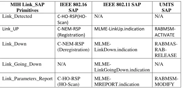
Table 1 represents the mapping of the SAP primitives for IEEE 802.16, IEEE 802.11 and UMTS onto the MIH Link SAP primitives [1, 9]. These mappings are used in the handover and simulation scenarios described in the upcoming sections. The MIH SAP primitive Link_Detected is triggered by the link specific primitives when the network for that technology becomes reachable. There is no corresponding primitive for Link_Detected in IEEE 802.11 and UMTS, however in IEEE 802.16 the C_SAP primitive C-HO-RSP for handover scanning triggers Link_Detected towards the MIHF. The Link_UP primitive of the MIH Link SAP is triggered by C-NEM-RSP which is the C-SAP primitive in IEEE 802.16 for registration and ranging response, MLME-LinkUp.indication in IEEE 802.11 and RABMSMACTIVATE in the UMTS when a mobile node gets registered with network.
Table 1: MIH primitives mapping
MIH Link_SAP Primitives
IEEE 802.16 SAP
IEEE 802.11 SAP UMTS
SAP
Link_Detected C-HO-RSP(HO-Scan)
N/A N/A
Link_UP C-NEM-RSP
(Registration)
MLME-LinkUp.indication RABMSM-ACTIVATE
Link_Down C-NEM-RSP
(Deregistration)
MLME-LinkDown.indication
RABMAS- RAB-RELEASE
Link_Going_Down N/A
MLME-LinkGoingDown.indication N/A
Link_Parameters_Report C-HO-RSP (HO-Scan)
MLME-MREPORT.indication
International Journal of Computer Networks & Communications (IJCNC) Vol.3, No.6, November 2011
104
The Link_Down is MIH link SAP primitive triggered towards MIHF by IEEE 802.16 C_SAP primitive C-NEM-RSP with deregistration response, IEEE 802.11 primitive MLME-LinkDown.indication and UMTS primitive RABMASRAB-RELEASE-RELEASE when a mobile node deregisters or gets disconnected from the network. The Link_Going_Down has no corresponding primitives in IEEE 802.16 and UMTS, but in IEEE 802.11 MLME-LinkGoingDown.indication triggers the Link_Going_Down towards the MIHF when signal strength of the serving network becomes weaker. The Link_Parameters_Report indicates changes in link conditions. For the load balancing an additional parameter named as load with data type integer has been introduced in information element (IE) of MIIS. The MIIS primitives MIH_Get_Information.indication and MIH_Get_Information.confirm carry this value from MIIS to mobile node.
4.4 Detailed handover procedures
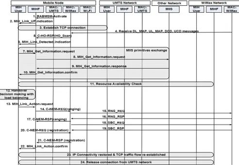
The handover scenarios considered in this paper cover the vertical handover procedures between UMTS, WiMax and Wi-Fi in such a way that it covers circumstances which trigger handover when mobile node enters and leaves these networks. Figure 5 shows the procedure and the SAP primitives involves in the handover from UMTS to WiMax. The step 1 in Figure 5 informs the MIHF that the mobile node is registered with the UMTS network. Step 2 informs the MIH User about the activation of link on mobile node’s UMTS interface. In step 3, a TCP connection is established between the mobile node and the TCP source using the UMTS network. Step 4 shows WiMax interface receives broadcast messages from WiMax BS. Step 5 signals the MIHF in the mobile node about WiMax network detection. Step 6 informs MIH User about WiMax link detection. Insequence of steps from 7 to 10 the mobile node acquire the neighbouring networks information from MIIS using a set of MIIS primitives, and step 11 checks the availability of required resources in WiMax network. Step 12 decides whether or not to perform handover to WiMax. In steps 13 to 22, the mobile node registers itself on WiMax. Step 23 is to establish a TCP connection between mobile node and TCP source using WiMax network. In step 24, mobile node releases its connections from the UMTS network.
International Journal of Computer Networks & Communications (IJCNC) Vol.3, No.6, November 2011
105
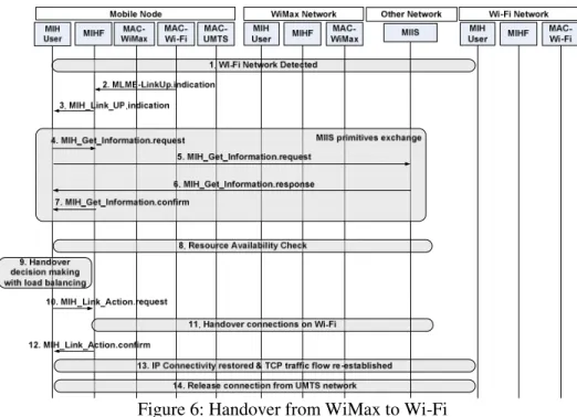
Similarly, Figure 6 shows the SAP primitives used in the handover procedure from WiMax to Wi-Fi. As represented by Figure 6 the 802.11 MAC layer in the mobile node, after detecting and registering with Wi-Fi network, it sends MLME-LinkUp.indication message to the MIHF. In step 3, MIHF sends MIH_Link_UP.indication to MIH User. A set of messages from step 4 to 7 acquire the neighbouring networks information. Step 8 checks for the required resources in Wi-Fi for handover. The MIH User decides whether to perform handover or not in step 9. Steps 10 to 12 show the handing over of the connections to the Wi-Fi network. Finally, step 13 and step 14 make sure that traffic flow has been re-establish between mobile node and TCP source and then release bindings with UMTS network. Figure 7 shows the handover procedure when mobile user moves away from the Wi-Fi coverage area and enters a WiMax coverage area.
The first step in Figure 7 is the message MLME_MREPORT.indication from MAC Wi-Fi to MIHF. This is the periodic message which carries parameters of link. In step 2 the MIH User is being updated with link parameters report. Step 3 shows the message link-Going_down from Wi-Fi MAC to MIHF, which represents that mobile node, is gradually losing the connectivity with Wi-Fi. Step 4 informs the MIH User about link going down event. From step 5 to step 8 are used to acquire neighbouring networks information from MIIS. Step 9 shown as bubble represents the process of scanning on all interfaces supported by mobile node. Step 10 and step 11 are for selecting the WiMax network and handover all connections to WiMax.
Figure 6: Handover from WiMax to Wi-Fi
International Journal of Computer Networks & Communications (IJCNC) Vol.3, No.6, November 2011
106
neighbouring networks information from MIIS using MIIS primitives. Step 11 shows the decision making process for selecting the candidate network for handover, UMTS is selected as it is the only available network. Step 12 represents the mobile node’s handover to UMTS. In step 13 all bindings with WiMax are being released.
Figure 7: Handover from Wi-Fi to WiMax
Figure 8: Handover from WiMax to UMTS
5.
S
IMULATION ARCHITECTURE&R
ESULTS5.1 Simulation architecture
International Journal of Computer Networks & Communications (IJCNC) Vol.3, No.6, November 2011
107
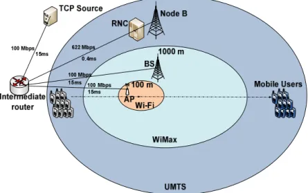
scenarios where mobile nodes can see maximum overlapped coverage areas from different networks. Each mobile user maintains a TCP connection with the TCP source shown in Figure 9 throughout the simulation such that effects of handovers on active connections can be measured.
The set of scenarios considered in this paper consist of a group of mobile users which travel across the coverage areas of all three networks such as UMTS, Wi-Fi and WiMax as shown in Figure 9. There are five scenarios simulated with different number of mobile users in group such as 5, 10, 15, 20 and 25. All mobile users support multiple interfaces such as UMTS, WiMax and Wi-Fi and use these interface throughout the simulation. Each of these five scenarios simulated with load balancing and without load balancing algorithm. When using the load balancing algorithm in RAT selection; the mobile users are assigned to the network by considering the overall load variation in the co-located networks; therefore it maintains the load equilibrium in the co-located networks. On other hand where load balancing approach is not utilized the mobile users move to the network with the strong signalling strength which creates a noticeable amount of load variation in the co-located neighbouring networks.
Figure 9: Network topology for simulation
International Journal of Computer Networks & Communications (IJCNC) Vol.3, No.6, November 2011
108
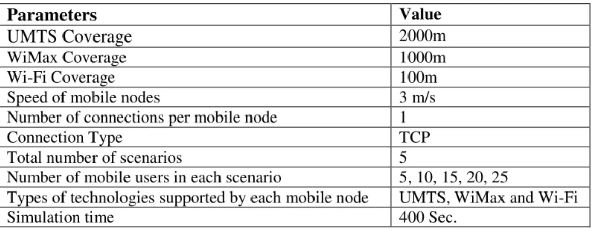
Table 2: Simulation parameters
Parameters
ValueUMTS Coverage
2000mWiMax Coverage 1000m
Wi-Fi Coverage 100m
Speed of mobile nodes 3 m/s
Number of connections per mobile node 1
Connection Type TCP
Total number of scenarios 5
Number of mobile users in each scenario 5, 10, 15, 20, 25
Types of technologies supported by each mobile node UMTS, WiMax and Wi-Fi
Simulation time 400 Sec.
5.2 Simulation Results
5.2.1 Load balancing performance
All scenarios discussed in the previous section have been simulated using NS2[20]. Figure 10 to Figure 13 represent the load distribution at each network in 5, 10, 15, 20 and 25 nodes scenarios with load balancing and without load balancing.
Figure 10:Scenario 1- 5 nodes
Figure 11:Scenario 2- 10 nodes
Figure 12:Scenario 4- 15 nodes
Figure 13: Scenario 4 - 20 nodes
International Journal of Computer Networks & Communications (IJCNC) Vol.3, No.6, November 2011
109
UMTS network. Similarly pink and yellow lines showthe network load for WiMax with and without load balancing respectively. For WiMax the graphs shows that without load balancing all the mobile nodes move to WiMax when it is available to them. After some time when Wi-Fi becomes available all mobile nodes move to Wi-Fi and WiMax become idle. Upon leaving the coverage area of Wi-Fi all the mobile nodes again join the WiMax network. With load balancing algorithm it can be noticed that WiMax network never stay idle as long as mobile nodes remain in the WiMax coverage area.It shows that with load balancing the WiMax network is utilized better as it never stays idle and not all the mobile nodes connect to it any time. The red and the cyan lines representing load at Wi-Fi show low load value with load balancing and high load without load balancing.
Table 3 shows the comparison of load in different networks for the simulation scenario of 25 nodes with and without load balancing. Load balancing also minimizes the connection/call blocking and dropping probabilities by sharing the load and maximizing the available networks resources. The term LB in the following Table 3 represents Load Balancing and NLB represents No Load Balancing or without load balancing.
Table 3: Load Table for 25 nodes scenario
Approximate
Time
Available Coverage UMTS Load WiMax Load Wi-Fi Load
NLB LB NLB LB NLB LB
0-10 seconds
UMTS only 25 25 0 0 0 010-60 seconds UMTS & WiMax 0 12 25 13 0 0 60-73 UMTS, WiMax & Wi-Fi 0 8 0 8 25 9
73-340 UMTS & WiMax 0 12 25 13 0 0
340-400 UMTS only 25 25 0 0 0 0
It is shown in the Figure 13 that without load balancing algorithm there have been a lot of load variation such that all the mobile users acquire the best available network, which results in one network overloaded and other nearly idle. On other hand if load balancing algorithm is used all the available networks are equally loaded, which gives the best utilization of available technologies and avoids the situation where one network gets overloaded while other having minimum load. For example in case of 25 node scenario without load balancing from time 0 to 10 sec UMTS has all 25 mobile users at time 10 sec all 25 users handover to WiMax and UMTS load becomes 0. Then at time 60 sec all 25 users handover to Wi-Fi and load of WiMax and UMTS becomes 0. When all mobile users leave the Fi coverage area at time 73 sec Wi-Fi load becomes 0 and WiMax load becomes 25. On other hand with load balancing the 25 mobile users scenario shows different load distribution. Load at UMTS goes to 25 initially but as WiMax becomes available UMTS load becomes 12 and WiMax load becomes 13 such that each available network gets equal load. After some time when Wi-Fi becomes available to the mobile users then load at UMTS and WiMax becomes 8 and load at Wi-Fi becomes 9. On leaving from the Wi-Fi coverage area the mobile users from Wi-Fi network move toUMTS and WiMax such that the load at UMTS becomes 12 and load at WiMax becomes 13.
International Journal of Computer Networks & Communications (IJCNC) Vol.3, No.6, November 2011
110
distribution of mobile nodes to the available networks. The graphs in the figures (from Figure 10 to Figure 13) are showing that load balancing maximizes the chances of availability of any network and minimizes network overloading situation by distributing the load in the co-located networks. These graphs also show that with load balancing idle state of network can also be avoided in parallel with avoiding network overloading state and hence increases the available resource utilization efficiently.
5.2.2 End-to-end delay
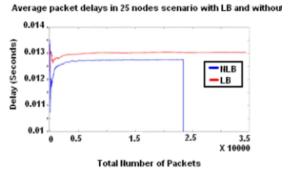
Figure 14 and Figure 15 show the average end-to-end delays for 5 and 25 nodes scenarios using load balancing algorithm and without load balancing algorithm. When there is no load balancing applied, all the mobile devices connect to the best available network and therefore the scenario results into lowerend-to-end delays for average transmitted packet throughout the simulation as compared to the scenario with load balancing algorithm. When load balancing algorithm is applied each mobile user is assigned the network by considering the load at that network. This results in a situation where different mobile users connect to different available networks, some of them have low end-to-end delay and some have high end-to-end delay resulting into slightly high average packet end-to-end delay. The red line in the following Figure 14 shows the average packet end-to-end delay in 5 nodes scenario with load balancing and blue line represents average packet end-to-end delay with no load balancing.Figure 14 and Figure 15 show the service degradation tradeoff in terms of increasing average packet end to end delay when using load balancing algorithm.
Figure 14: Average packet E2E delay with 5 mobile users
Figure 15: Average Packet E2E delay with 25 mobile users
On other hand it is also shown in the Figure14 and Figure 15 that total traffic exchanged is far more in scenario where load balancing algorithm is applied as compared to scenario where load balancing algorithm is not applied. The reason for this increase in total number of packet exchange is when load balancing is applied it utilizes the bandwidth available in all the available networks such as UMTS, WiMax and Wi-Fi. On other hand when load balancing is not applied only the network with strong signal strength and high data rate is utilized by all mobile users.
5.2.3 Jitters
International Journal of Computer Networks & Communications (IJCNC) Vol.3, No.6, November 2011
111
delay value or jitters remains minimum, whereas without load balancing all the mobile users moves frequently as they see new best available network which cause higher jitters. Figure 16 and Figure 17 show the average packet jitters values throughout the simulation for 5 and 25 mobile users’ scenarios with load balancing and without load balancing.
Figure 16: Average Packet Jitters for
5 mobile users
Figure 17: Average Packet jitters for
25 mobile users
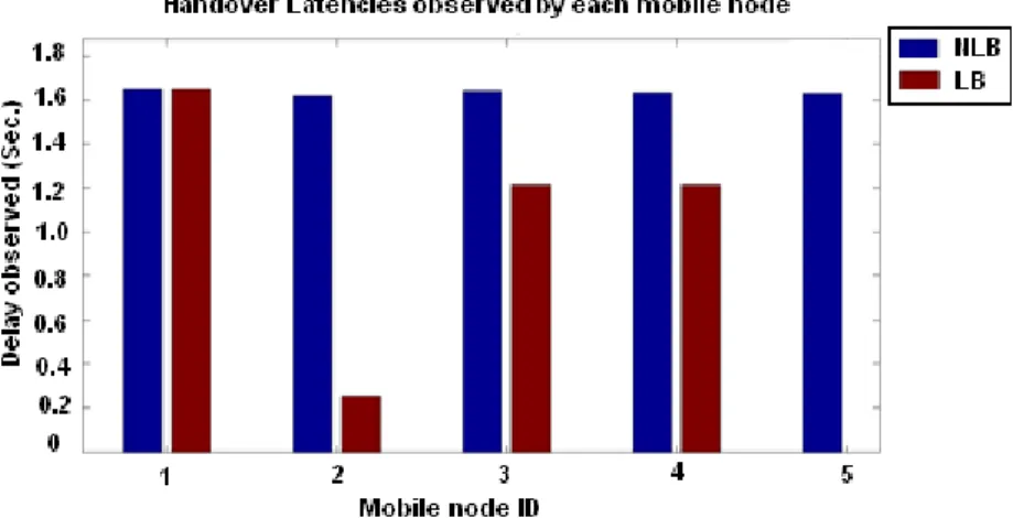
5.2.4 Handover latencies
The handover latencies have been calculated for each scenario in the simulation by taking the difference between the time of the first packet received in the target network and the time of last packet received on previous serving network. Figure 18 to Figure 22 show the total handover latencies observed by each mobile user in different scenarios having different number of mobile users. While the blue bars represent handover latencies observed by each node without load balancing algorithm, the brown bars represent handover latencies observed by each mobile node with load balancing algorithm.
Figure 18: HO Latencies in 5 mobile users scenario
International Journal of Computer Networks & Communications (IJCNC) Vol.3, No.6, November 2011
112
latencies of 5 mobile users scenario, it can be concluded that without load balancing all five mobile users perform equal number of handovers and with load balancing at least one mobile user stays in UMTS network throughout the simulation.Figure 10 shows the load distribution at 5 nodes scenario represents that at least five different levels of total HO latencies values are expected which is validated in the Figure 18 showing the total handover latencies in 5 mobile users scenario. Similar to the bar graph shown in the Figure 18, the Figure 19 to Figure 22 show total handover latencies observed by each mobile user in 10,15,20 and 25 mobile users scenarios respectively.
Figure 19: HO Latencies for 10 mobile users
Figure 20: HO Latencies for 15 mobile users
Figure 21: HO Latencies for 20 mobile users
Figure 22: HO Latencies for 25 mobile users
International Journal of Computer Networks & Communications (IJCNC) Vol.3, No.6, November 2011
113
not change the end to end delays frequently. The average handover latencies observed by each mobile user in scenarios with load balancing is lower as compared to the scenarios without load balancing as load balancing algorithm reduces the number of handovers for most of the mobile users.
6.
C
ONCLUSIONIn this paper a load aware RAT selection algorithm has been presented with the comparison of results generated by simulation scenarios using load balancing algorithm and without load balancing. Four different attributes have been compared in both types of scenarios such aswith load balancing algorithm and without load balancing.Considered attributesfor observation are load distribution on each of the available network, average packet end to end delay, average packet jitter values and handover latencies. The results showed that with load balancing all three parameters showed improvement in the target heterogeneous wireless network architecture; apart from average end to end delay, which increased slightly for the scenarios using load balancing algorithm. As with load balancing not all the mobile users gets the best available network therefore end-to-end delay for those mobile users go high degrading the overall performance to some extent. Load balancing algorithm assures the fair load distribution between the overlapping networks whereas without load balancing different networks show abrupt load variationswhich decrease the performance with high congestion, high call dropping probability and blocking probability at overloaded network. Load balancing approach utilizes the available radio resources efficiently. Handover latencies are minimized, as it does not require all the mobile users to handover when load balancing algorithm is used. Hence the load aware RAT selection is a better approach as it offershigh radio links utilization with minimum number of handovers and hence low handover delays, minimizedcall/connection blocking and dropping probability and ability to maximize the network availability with uniformly distribution of load in co-located networks. With load balancing algorithm there is an end-to-end delay tradeoff, which is very small and in some cases negligible if underneath running application is tolerant to very little increase in delays.
R
EFERENCES[1] IEEE Std. 802.21, Media Independent Handover Services, 2009.
[2] N. Efthymiou, Y. F. Hu, R. E. Sheriff, “Performance of Intersegment Handover Protocols in an Integrated Space/Terrestrial-UMTS Environment”, IEEE TRANSACTIONS ON VEHICULAR TECHNOLOGY, VOL. 47, NO. 4, NOVEMBER 1998.
[3] A. H. Aghvami, P. Smyth, “Forward or backward handover for W-CDMA”, 3G Mobile Communication Technologies, First International Conference, 2002.
[4] C. Chrysostomou, A. Pitsillides, F. Pavlidou, “A Survey of Wireless ATM Handover Issues”, International Symposium of 3G Infrastructure and Services, 2001.
[5] IEEE std. 802.11, “Wireless LAN Medium Access Control (MAC) and Physical Layer (PHY) Specifications”, 1999.
[6] Smith, Clint, “3G wireless with WiMAX and Wi-Fi: 802.16 and 802.11”, McGraw-Hill, 2005. [7] IEEE std. 802.16, “Air Interface for Broadband Wireless Access Systems”, 2009.
International Journal of Computer Networks & Communications (IJCNC) Vol.3, No.6, November 2011
114 Network and Terminals; Mobile radio interface signalling layer 3; General aspects”, Release 8, V8.2.0 (2009-06).
[10] Walke, Bernhard, “UMTS: the fundamentals / B. Walke, P. Seidenberg, M.P. Althoff”, John Wiley, 2003.
[11] Kreher, Ralf, “UMTS signaling: UMTS interfaces, protocols, message flows and procedures analyzed and explained”, John Wiley & Sons, 2005.
[12] Shiann-Tsong Sheu and Chih-Chiang Wu, “Dynamic Load Balance Algorithm (DLBA) forIEEE 802.11 Wireless LAN”, Tamkang Journal of Science and Engineering, vol. 2, No. 1 pp. 45-52 (1999).
[13] IoannisPapanikos and Michael Logothetis, “A Study on Dynamic Load Balance for IEEE 802.11b Wireless LAN”, 8th International Conference on Advances in Communications and Control, COMCON'01, June 2001.
[14] Ted Scully, Kenneth Brown,“Wireless LAN load balancing with genetic algorithms”, KnowledgeBased Systems, (2009).
[15] Mun-Suk Kim and SuKyoung Lee, “Load balancing and its performance evaluation for layer 3and IEEE 802.21 frameworks in PMIPv6-basedwireless networks”, WIRELESS COMMUNICATIONS AND MOBILE COMPUTING, Wirel. Commun. Mob. Comput. (2009), DOI: 10.1002/wcm.832.
[16] SuKyoung Lee, KotikalapudiSriram, Kyungsoo Kim, Yoon Hyuk Kim, and Nada Golmie, “Vertical Handoff Decision Algorithms for Providing Optimized Performance in Heterogeneous Wireless Networks”, IEEE TRANSACTIONS ON VEHICULAR TECHNOLOGY, JANUARY 2009.
[17] Alexandros Kaloxylos, IoannisModeas, FotosGeorgiadis and Nikos Passas, “Network Selection Algorithm for Heterogeneous Wireless Networks: from Design to Implementation”, Network Protocols and Algorithms, ISSN 1943-3581, 2009, Vol. 1, No. 2.
[18] Kamil H. Suleiman, H. Anthony Chan, Mqhele E. Dlodlo, “Load Balancing in the Call Admission Control ofHeterogeneous Wireless Networks”, IWCMC’06, July 3–6, 2006, Vancouver, British Columbia, Canada.
[19] Abdallah AL Sabbagh, “A Markov Chain Model for Load-Balancing Based and Service Based RAT Selection Algorithms in Heterogeneous Networks”,World Academy of Science, Engineering and Technology 73 2011.
![Figure 1: MIH Reference Model [1]](https://thumb-eu.123doks.com/thumbv2/123dok_br/18117945.323832/4.918.293.598.265.490/figure-mih-reference-model.webp)