ISSN: 1546-9239
©2012 Science Publication
doi:10.3844/ajassp.2012.1891.1898 Published Online 9 (11) 2012 (http://www.thescipub.com/ajas.toc)
METHODICAL TUNING OF PROPORTIONAL PLUS INTEGRAL
CONTROLLERS FOR CASCADE CONTROL OF SEPARATELY
EXCITED DC MOTORS
Ibrahim Al-Abbas
Department of Mechatronics Engineering,
Faculty of Engineering Technology, Al-Balqa Applied University, Amman, Jordan Received 2012-06-27, Revised 2012-09-07; Accepted 2012-09-12
ABSTRACT
The cascade control of DC motors by PI controllers was extensively used in industry. Approximation rules based on plotting the output of the system or on computer simulation were used to determine the parameters of these controllers. This study was done to develop mathematical expressions to calculate the parameters of these controllers. Output time functions of the system and there derivatives were used to obtain mathematical relationships relating directly the motor parameters and the controller parameters. These relationships were used in tuning process of the cascade system. The dynamic performances of the system were examined in single loop form and in closed loop form for a step change in control variable (the input voltage) as well as for step change in disturbance (mechanical load). The performances of current closed loop system and the speed closed loop were acceptable. The steady state error was zero and the maximum overshoot was less than 20%. The developed relationships can be used in design and analysis of cascade DC drive systems and cascade AC drive systems.
Keywords: Cascade Control, DC Motor, Ziegler Nichols, PI Control
1. INTRODUCTION
Cascade control of Separately Excited Direct Current (SEDC) motors can improve system performances over single-loop control, the control system has inner (current) loop and outer (speed) loop, where Proportional Plus Integral (PI) controller is implemented in each loop to provide fast response and zero steady state error. Different methods are used to select the gain and the time constant of PI controllers, these methods can be classified into three groups: The first one is Ziegler Nichols tuning rules used the plotted output time response curves (Sing and Pandey, 2012). Lee (2004) used the calculated gain margin and phase margin of the open loop system, it is known that gain and phase margins have served as important measures of robustness. The phase margin is related to the damping of the system from classical control theories and therefore also serves as a performance measurement. Their solutions are normally obtained numerically or graphically using bode plots. Moleykutty (2008) proposed a second method based on trial and error tuning of the controller from the simulated cascade
SEDC motor. The third method is the transfer function approach (Neenu and Poongodi, 2009) where the order of the open loop system is reduced to a second order with known parameters. To implement these methods some specifications should be measured to design the controller, therefore they can considered as indirect tuning methods.
has an inflection point at time tinf, where the first derivative reaches its maximum value and the second derivative is zero.
Traditional tuning method used measuring to determine the parameters of this response: L-the delay time and T-the time constant by plotting tangent at inflection point as shown on Fig. 2.
To determine the delay time and the time constant of response analytically we follow the following steps:
Step1: From the known time function y(t), determine
the first derivativey (t)′ and the second derivative y (t)′′
Step2: Equating the second derivative to zero and solving this equation obtain tinf, the time where thereaction curves exhibit inflection
inf inf y(t ) tan
t L
α =
− Or: inf inf y(t ) L t
tan
= −
α (1)
Step 5: Using the triangular(b1,b4,b5) on Fig. 2 find T:
ss y tan
T
α = , or yss T
tan =
α (2)
where the steady state value of the output yss:
ss t y Limy(t)
→∝
= (3)
Step6: Use the calculated reaction curve parameters L and T and Ziegler-Nichols rules to tune the PI controller.
Fig. 1. Reaction curve y (t) and its derivatives
Fig. 3. Closed loop armature current block diagram
Fig. 4. Closed loop speed control system block diagram Equations (1-3) show how the output and its
derevatives can be used to obtain reaction curve parameters.
2.2. Armature Current PI Controller Design
The current controller is designed for the extreme condition when back emf is zero, that is during starting period because at that time large current flows through the machine. The block diagram of the clopsed loop armature current is depicted on Fig. 3 where: Ra the armature resistance, La the armature inductance, Kr rectifier gain, Tr rectifier time constant, Kc PI controller gain and Tc PI controller time constant.
The plant transfer function is equation 4:
a r a
p
c a r
I (s) K / R G (s)
V (s) (T s 1)(T s 1)
= =
+ + (4)
Assume a step change in Vc and taking inverse Laplace transform of both sides, we obtain the armature current and its derivatives:
a
r
t / T
c r a
a
a a r
t / T r r a
V K T
i (t) (1 e
R T T
T e ) T T − − = − − − − (5) a r
t / T t / T c r
a
a a r
V K
i ( t ) (e e )
R (T T )
− −
′ = −
− (6)
a r
t / T t / T c r
a
a a r a r
V K 1 1
i ( t ) ( e e )
R (T T ) T T
− −
′′ = − +
− (7)
Equation (5) indicates that the armature current has two exponential terms and a constant term, that is mean
the output is of S-shape. The first derevative given by equation (6) has a maximum value and its derevative represented by equation (7) has an intersection point with real axis.These specifications will be used to determine reaction curve parameters.
Equating the second derivative given by equation (7) to zero and solving for inflection time results:
a r a inf
a r r
T T T
t ln
T T T
=
− (8)
Without ploting the output of the loop i(t).using equations (8) and (7) the angle of the tangent to the reaction curve can be calculated, then using equations (1) and (2) the parameters of the response are obtained and implemented in tuning the PI controller and for better response modified Ziegler-Nichols rules are used in this study.
2.3. Speed PI Controller Design
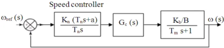
The block diagram of the closed loop speed control system is presented on Fig. 4 where Kb is the torque constant, B is the viscous friction coefficient, Tm is the mechanical time constant, Kn and Tn are the speed PI controller gain and time constant respectively, Gc(s) is the armature current closed loop transfer function. Tn should be chosen such that it cancels the largest time constant in the transfer function in order to reduce the order of the system. Therefore the response will be much faster. The speed open loop transfer function is equation (9):
n 0 1 n
4 3 2
0 1 2 3
K b s b K a s a s a s a s
+
+ + + (9)
1 c a r c r a
a =T Tm(L +T )+T T L (13)
a2=T (T Rm c a+K K L )r c a +T (Tc r+L )a (14)
3 m r c a c a r c a
a =T K K R +T R +K K L (15)
4 r c a a
a =K K R (16)
Equations (10-16) give the relatinoships between the system parameters and the coefficients of the trsnsfer functin of the same system and will be used in determing the critical gain and the critecal period nessecary to tuned the speed PI controller.
The speed open loop system has a zero on the origin and the time response exhibits sustained oscillations when the proportional gain is at critical value Kcr, this critical value can be obtain theoretically from the Routh’s stability criterion using the following speed closed loop transfer function:
ref n 0 1 n
4 3 2
0 1 2 3 n 0 4 1 n
(s) K b s b K
(s) a s a s a s (a K b )s a b K
ω = + →
ω + + + + + + (17)
The characteristic equation (17) of the speed closed loop system is:
4 3 2
0 1 2 3 n 0 4 1 n
a s +a s +a s +(a +K b )s a+ +b K =0 (18)
From equation (18)arrange Routh’s array as shown on Table 1,where:
1 2 0 3 0 0 n 1 2 0 3 n 0
2
3 n 0 1 1 n 4
(a a a a a b K ) A
a a a (a K b )
(a K b ) a b K a
− − = → − + + − + → (19)
Examining the array of coefficients, the speed closed loop system becomes oscillatory when A equals zero, i.e:
1 2 0 3 0 0 cr 3 0 cr 2
1 1 cr 4
(a a a a a b K )(a b K ) a (b K a ) 0
− − + +
− + = (20)
S0 a4+b1Kn 0
Solving Equation 19, for critical gain results:
2
cr 1 1 2
K =−K ± (K −K ) (21)
Where:
2 0 0 3 1 2 1 1
1 2
0 0 b (2a a a a a b K
2a b
− +
= (22)
2 3 0 3 1 2 1 4
2 2
0 0 a (a a a a ) a a K
2a b
− +
= (23)
The proportional gain of speed PI controller is determined using the calculated critical gain, equations (18-23) and the modified second Ziegler Nichols method for low overshoot of the output signal.
To find the frequency of the sustained oscillations a supplementary equation is performed using the coefficients of the third raw in Routh’s table as:
2 1 2 0 3 cr 0
4 1 cr 1
a a a (a K b )
s a b K 0
a
− + + + = (24)
Replacing s by jω and solving equation (24):
1 1 cr 4 cr
1 2 0 3 0 cr 0
a ( b K a )
j
(a a a a a K b )
+ ω = ±
− − (25)
The period of sustained oscillation is:
cr cr
P = π ω2 / (26)
Equations (24-26) determened the critical period of the speed closed loop system,then the parameters of the PI speed controller can be adjusted from the calculated critical gain and critical period.
2.4. Cascade System Simulation
A double loop cascade control system is simulated using the following components.
1: 5 HP, 240V separately excited DC motor with parameters as:
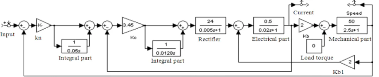
Fig. 5. MATLAB/Simulink model of cascade system Back EMF Constant Ke = 2 Volt.sec/rad.
Rated Current = 16 A.
Resistance of Armature, Ra = 0.5 ohm. Armature Inductance, La = 0.01H.
Viscous friction coefficient, B = 0.02Nm/rad/s Mechanical time constant Tm=J/B s
Torque constant KB = Ke/B
2: Single phase rectifier:
Rectifier gain, Kr = 24
Rectifier time constant, Tr=0.005 s Input control signal, Vc = 10 V
3: PI current controller:
Proportional gain, Kc = 3.45 Integral time constant, Tc = 0.0128 s
4: PI speed controller:
Proportional gain, Kn = 0.96 Integral time constant, Tn = 0.05 s
The components of the cascade system connected together are shown on Fig. 5 where the current loop contains the armature circuit (electrical part), the rectifier and PI current controller and the speed loop contains the closed loop current loop, mechanical part and PI speed controller.
3. RESULTS
In order to validate the control strategies were developed, simulations are carried out. These simulations are made for current control loop and for speed control loop.
3.1. Armature Current Closed Loop Response
The dynamic performances of the closed loop armature current are obtained using MATLAB/Simulink model of cascade system shown on Fig. 5 when the PI speed controller is disconnected and the reference signal is applied directly to the PI current controller.
Fig. 6. Current loop start up time response
3.2. Angular Speed Closed Loop Response
The start up time response of the speed closed loop
system is shown on Fig. 8 with no load and with rated load. These two curves indicate that disturbance in cascade system has no effect on the dynamic performances.
On Fig. 9 the time response of the speed loop for step change on motor load applied at t = 0.5 sec is plotted. The speed of cascade system oscillates in the region of
its steady state value and then go back to the speed Fig. 8. Speed loop start up time response
Fig. 9. Speed loop time response to step change on load torque
Fig. 11. Time response of the hall system To achieve preferred overshoot for the speed loop,
Crnosija et al. (2005) inserted a filter with unity gain and different value of time constant on the system input. If the time constant of the input filter is 0.02 sec, the percent maximum overshoot is reduced from 70 to 10% as exposed on Fig. 10.
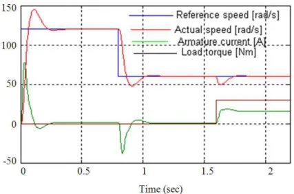
The maximum overshoot can be reduced by tuning the parameters of PI speed controller especially the integration time constant Tn, but the speed of the system response is lower. Finally, the time response of the drive system is presented on Fig. 11. When the reference signal is reduced by 50% at t = 0.8 sec and the load torque is increased to its nominal value at t = 1.6 sec.
4. DISCUSSION
This study covers an analytical method for design of double loop cascade system contains a separately excite DC motor and full controlled single phase rectifier. For inner loop (armature current loop), using the armature current time function and its derivates a mathematical expressions are derived for reaction curve parameters, they are the delay time (l) and the Time constant (T), these two parameters are used to calculate the gain and time constant of a proportional plus integral controller, the calculated parameters are implemented in simulations investigation the time response performances of this loop.
For the outer loop (speed loop), critical gain and the critical period of the oscillated response are determined using developed relation ships and implemented to determine the speed PI controller parameters. The
dynamic behavior of the speed closed loop is analyzed using Simulink software. Different tuning rules for both controllers were examined during simulations.
The time response of the armature current closed loop is fast, has zero steady state error and acceptable overshoot for DC motors. The time response of the speed closed loop has one disadvantage which that a high percent overshoot but its corrected using a filter in the input of the system
5. CONCLUSION
In the present study, a mathematical expression for armature current PI controller and for speed of rotation PI controller are derived and used in calculations of the gain and of the time constant for both controllers. The cascade system is simulated and the time response is plotted and investigated. For current loop it is better to adjust the parameters of PI controller applying modified Ziegler-Nichols first method to reduce the overshoot of the armature current, while for speed PI controller it is reasonable to implement modified second Ziegler-Nichols method for small overshoot and tune the integrator time constant, or better introduce a filter into the input of the system.
on Industrial Electronics, Jun. 20-23, IEEE Xplore
Press, pp: 881-886. DOI:
10.1109/ISIE.2005.1529040
Lee, C.H., 2004. A survey of PID controller design based on gain and phase margin. Int. J. Comput. Cognit., 2: 63-100.
Moleykutty, G., 2008. Speed control of separately excited DC motor. Am. J. Applied Sci., 5: 227-233. DOI: 10.3844/ajassp.2008.227.233