Pedro Miguel Lucas Arsénio
M. Sc. in Electrical and Computer Engineering
Contribution for the Study of Inductive
Fault Current Limiters in Electrical
Distribution Grids
Dissertation to obtain the degree of Doctor of Philosophy in
Electrical and Computer Engineering
Supervisor: João Miguel Murta Pina
Assistant Professor
Universidade Nova de Lisboa, Portugal
Co-supervisor: Anabela Monteiro Gonçalves Pronto
Assistant Professor
Universidade Nova de Lisboa, Portugal
Co-supervisor: Alfredo Álvarez García
Full Professor
Universidad de Extremadura, Spain
Evaluation board:
President: Doctor Paulo da Costa Luís da Fonseca Pinto Opponents: Doctor István Vajda
Doctor Guilherme Gonçalves Sotelo Members: Doctor José María Ceballos Martínez
Doctor João Francisco Alves Martins Doctor João Miguel Murta Pina
Contribution for the Study of Inductive Fault Current Limiters in Electrical Distribution Grids
Copyright © Pedro Miguel Lucas Arsénio, Faculdade de Ciências e Tecnologia, Universidade Nova de Lisboa.
Acknowledgements
Acknowledgments
Doing a PhD was indeed a great and interesting task. During this period of my life, I was able to improve my skills, knowledge, network, among others. It was a challenging journey and it was not only my professional experience that was grown, my personal experience was enriched due to many life lessons that I learned.
I would like to thank my supervisor, João Murta Pina and my co-supervisors, Anabela Pronto and Alfredo Álvarez for their support, guidance, knowledge, and suggestions which helped me to reach this stage. Their supervision was essential.
I express my gratitude to the Portuguese Fundação para a Ciência e a Tecnologia for enabling me to pursue my PhD degree with a concession of an individual scholarship (reference SFRH/BD/85122/2012).
To UNL-FCT and UNINOVA-CTS for giving me all the necessary conditions to conduct my studies and work. I am grateful to the secretariat staff of the Electrical Engineering Department, namely Cristina, Elsa, and Helena for supporting all my academic needs.
I would like to express my gratitude to my colleagues and lab mates Fábio Januário, Nuno Amaro, Nuno Vilhena and Rui Lopes. They were present in almost all my working days and helped me surpassing stressing moments. By means of his high technical skills, I thank again Nuno Vilhena due to the development of a Rogowski coil, cryostats and several small things (which are not so small) that helped me a lot in this work.
I am thankful to all Professors of the University who taught me. With no exception, all of them gave me many important lessons. Those from the section of energy and electrical machines, namely Pedro Pereira, João Martins, Mário Ventim Neves and Stanimir Valtchev (besides my supervisors), I am very thankful for their deep support in each need.
I thank all efforts made by Pilar Suárez, José Ceballos, Belén Pérez and Antonio Guerra from “Benito
Mahedero” research group, to support my needs during my lab experiments at Badajoz.
To Isabel Catarino, from LIBPhys-UNL, for her practical and theoretical support with temperature measurements. Her deep knowledge helped me surpassing some difficult parts of the work.
To Pablo Vigarinho for his help with the encapsulation of etched superconducting tapes into resin for microscopy and spectroscopy analyses.
Acknowledgements
To my soulmate, Bruna, no words can describe my feelings about you. You certainly know I am so thankful to you. You always be there.
For those I have not mentioned, I apologise but I am not certainly forgetting about you in my thoughts and I am thankful to all of you for being part of my life.
Abstract
Abstract
Inductive type fault current limiters with superconducting tapes are emerging devices that provide technology for the advent of modern electrical grids, helping to mitigate operational problems that such grids can experience as well as preventing the often-costly upgrade of power equipment, namely protections. The development of such limiters leads to several design challenges regarding the constitutive parts of those devices, namely the magnetic core, primary winding and superconducting secondary.
Fault current limiters are required to operate at overcurrents during a certain amount of time. The operation at such currents can lead to harmful effects due to mechanical, electromagnetic and thermal stresses, especially in the superconducting tape. Since the operation principle of fault current limiters envisaged in this thesis is based on the superconducting-normal transition of superconducting materials, the study of its transient behaviour is an important research subject.
In this work, an electromagnetic methodology based on the characteristics of the constitutive parts of the limiters, previously developed and compared to finite element modelling simulations with very similar results, is simulated and validated with experimental results. Furthermore, the current in the superconducting tape is modelled from experimental results with the purpose of predicting the temperature of the material during normal and fault operation conditions, by employing a thermal-electrical analogy. These results are also compared to experimental measurements. A fast simulation tool, with computation times in the order of minutes, is also developed in Simulink, from Matlab environment.
With the developed simulation tool, it is possible to quickly predict the transient electromagnetic-thermal behaviour of an inductive type fault current limiter operating in electrical grids, namely the line current and primary linked flux, as well as current and temperature in the superconducting tape.
Keywords: Electromagnetic-Thermal Coupling, Inductive Fault Current Limiters, Modelling,
Resumo
Resumo
Os limitadores de corrente de defeito do tipo indutivo com fitas supercondutoras são dispositivos emergentes que fornecem tecnologia para o advento das redes elétricas modernas, ajudando a mitigar problemas operacionais que tais redes podem experienciar, assim como prevenir uma atualização, geralmente dispendiosa, do equipamento da rede, nomeadamente ao nível das proteções. Do desenvolvimento de tais limitadores, decorrem diversos desafios de desenho respeitantes às partes constitutivas desses dispositivos, nomeadamente o núcleo magnético, enrolamento primário convencional e o secundário supercondutor.
É requisito que os limitadores de corrente de defeito operem em regime de sobrecorrente. Tal regime de operação pode conduzir a efeitos potencialmente destrutivos devido a esforços mecânicos, eletromagnéticos e térmicos, em especial na fita supercondutora. Uma vez que o princípio de operação dos limitadores de corrente de defeito abordados nesta dissertação é baseado na transição entre as fases supercondutora-normal dos materiais supercondutores, o estudo do comportamento transitório é um importante assunto de investigação.
Neste trabalho, uma metodologia assente nos princípios eletromagnéticos e baseada nas caraterísticas das partes constitutivas dos limitadores, previamente desenvolvida e comparada a simulações por elementos finitos com resultados bastante semelhantes, é simulada e validada com recurso a resultados experimentais. Adicionalmente, a corrente na fita supercondutora é modelizada a partir de resultados experimentais com o propósito de determinar a temperatura do material durante operação normal e em falha, utilizando uma analogia térmica-elétrica. Estes resultados também são comparados com medições experimentais. Uma ferramenta de simulação rápida, com tempos de computação na ordem dos minutos, fora, também, desenvolvida em Simulink, do ambiente de computação Matlab.
Com recurso à ferramenta de simulação desenvolvida, é possível determinar, de uma forma rápida, o comportamento transitório eletromagnético-térmico de um limitador de corrente de falha indutivo em redes elétricas, designadamente a corrente de linha e fluxo ligado com o primário, assim como a corrente e temperatura na fita supercondutora.
Palavras-chave: Acoplamento Eletromagnético-térmico, Fitas Supercondutoras, Limitadores de
List of Contents
List of Contents
1 Introduction ... 1
1.1 Background and Motivation ... 2
1.2 Research Problem ... 3
1.3 Objectives ... 4
1.4 Outline of the Thesis... 4
1.5 Original Contributions ... 5
1.6 Publications ... 7
2 Literature Review ... 9
2.1 Faults and Protection of Electrical Grids ... 9
2.1.1 Types of Faults ... 9
2.1.2 Fault Current Protection ... 10
2.2 Superconducting Materials for Applications on Current Limitation ... 15
2.2.1 Bulks ... 16
2.2.2 Tapes ... 17
2.3 Thermal Properties of Superconducting Tapes ... 17
2.3.1 Heat Transfer Mechanisms ... 18
2.3.2 Absorption of Heat by Solids and Liquids ... 18
2.3.2.1 Thermal Conductivity ... 18
2.3.2.2 Heat Capacity ... 19
2.3.2.3 Convective Heat Transfer Coefficient ... 19
2.4 Joining of Superconducting Tapes ... 19
2.5 Simulation of Inductive FCLs ... 21
2.5.1 Lumped-Parameters Circuit Modelling ... 24
2.5.1.1 Steinmetz Equivalent Circuit Model ... 24
2.5.1.2 Time-variable Resistances and Inductances ... 25
2.5.2 Finite Element Method ... 25
2.5.3 Electromagnetic-Thermal Coupling ... 25
2.5.4 Characteristic Hysteresis Loops Methodology ... 27
2.6 Development Status of Inductive FCLs ... 29
2.6.1 Hydro-Quebec 100 kVA FCL ... 30
2.6.2 ABB 1.2 MVA FCL ... 33
2.6.3 CRIEPI FCL Project ... 34
2.6.4 Nagoya University SFCLT Project ... 37
2.6.5 Bruker 40 MVA FCL ... 39
2.6.6 IEL 6 kV/0.6 kA ... 40
List of Contents
3 Design and Modelling of the Inductive FCL ... 43
3.1 Constitutive Parts of the Limiter... 43
3.1.1 Magnetic Core ... 44
3.1.2 Primary ... 45
3.1.3 Secondary ... 46
3.2 Modelling in Transient States ... 50
3.2.1 Electromagnetic-Thermal Behaviour of the Superconducting Tape ... 50
3.2.1.1 Critical Current Density and n-value ... 51
3.2.1.2 Resistivity ... 53
3.2.1.3 Thermal Conductivity ... 56
3.2.1.4 Volumetric Heat Capacity ... 56
3.2.1.5 Convective Heat Transfer ... 57
3.2.2 Electromagnetic-Thermal Behaviour of the Limiter ... 59
3.2.2.1 Maximum Hysteresis Loop ... 59
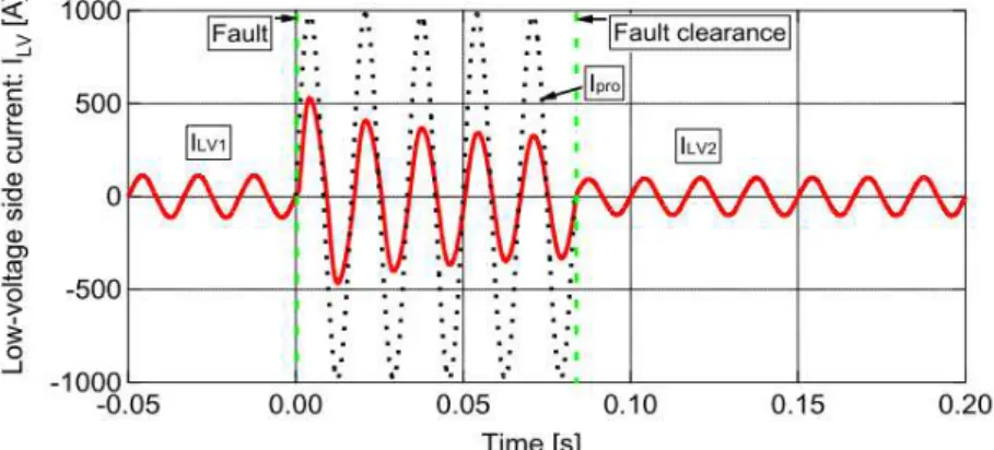
3.2.2.2 Current in the Superconducting Ring During Short-circuit Faults ... 64
3.3 Summary ... 68
4 Simulation of the Inductive FCL ... 71
4.1 Methodology... 71
4.1.1 Determination of Limited Current ... 72
4.1.1.1 Architecture of the Simulink Model ... 73
4.1.1.2 Logic Block ... 73
4.1.1.3 Limiting Current Determination Block ... 74
4.1.1.4 Current Control Block ... 75
4.1.2 Determination of Temperature ... 75
4.1.3 Solution Routine ... 78
4.2 Simulation Results ... 79
4.2.1 Line Current ... 79
4.2.2 Primary Linked Flux ... 80
4.2.3 Hysteresis Loop ... 81
4.2.4 Superconducting Current ... 82
4.2.5 Temperature in Superconductor ... 83
4.3 Summary ... 86
5 Experimental Validation of Models ... 87
5.1 Experimental Details ... 87
5.1.1 Experimental Apparatus ... 88
5.1.2 Rogowski Coil ... 92
5.1.3 DT-670 Silicon Diode ... 93
List of Contents
5.2.1 Line Current ... 96
5.2.2 Primary Linked Flux ... 96
5.2.3 Hysteresis Loop ... 97
5.2.4 Superconducting Current ... 98
5.2.5 Temperature in Superconductor ... 99
5.3 Summary ... 100
6 Conclusions ... 103
6.1 Summary and Discussion ... 103
6.2 Future Work... 106
References ... 109
Appendix A ... 121
Dimensions of Celeron Holder ... 121
Dimensions of Cryostat ... 122
Appendix B ... 123
Resin Encapsulation Procedure and Metallographic Preparation ... 123
Appendix C ... 125
Dimensions of Holder for Ring Type Joining ... 125
Appendix D ... 129
Simulated and Experimental Line Current ... 129
Simulated and Experimental Primary Linked Flux... 131
Simulated and Experimental Hysteresis Loop ... 133
Simulated and Experimental Superconducting Current ... 135
List of Figures
List of Figures
Figure 2.1 – Power system faults. ... 10
Figure 2.2 – Possible locations of FCLs in the electrical power grids. ... 12
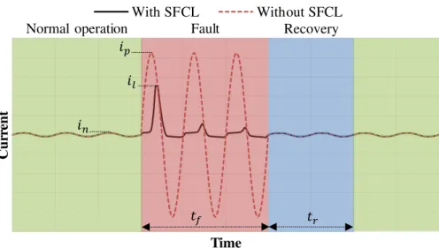
Figure 2.3 – Line current behaviour subjected to different regimes of operation with and without an FCL... 13
Figure 2.4 –Types of symmetrical short-circuit faults in 3-phase systems. ... 14
Figure 2.5 –Types of asymmetrical short-circuit faults in 3-phase systems... 14
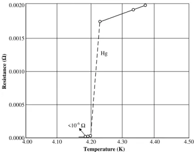
Figure 2.6 – Electrical resistance of mercury as a function of temperature, measured by Onnes. ... 15
Figure 2.7 – Superconducting bulks for experimental tests. (a) Magnetic levitation block. (b). Magnetic shielding cylinder. ... 16
Figure 2.8 – Configuration of SuperPower SCS4050 HTS coated conductor. ... 17
Figure 2.9 –Types of joints. (a) Lap joint. (b) Bridge joint. ... 20
Figure 2.10 – Examples of joining holders. (a) Linear type. (b) Ring type. ... 21
Figure 2.11 – Single-phase equivalent circuit with a resistive type FCL. The HTS is shunted with another conductor in order to prevent irreversible damage during quench. ... 22
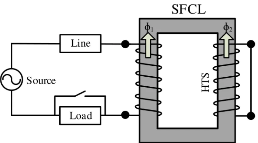
Figure 2.12 – Conceptual diagram of an inductive type FCL with a closed magnetic core. ... 22
Figure 2.13 – Single-phase equivalent circuit with an inductive type FCL. ... 23
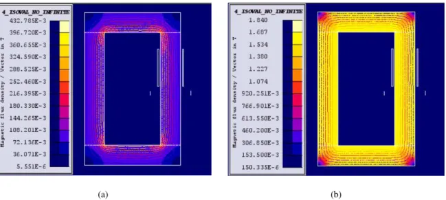
Figure 2.14 – Magnetic flux density map of the limiter simulated in Cedrat Flux2D. (a) Normal operation. (b) Fault operation. ... 23
Figure 2.15 – Steinmetz equivalent circuit referred to primary. ... 24
Figure 2.16 – Thermal-electrical equivalent circuit of a layer. ... 26
Figure 2.17 – Maximum hysteresis loop of an inductive type FCL. ... 28
Figure 2.18 – Simulation grid with an inductive type FCL. ... 28
Figure 2.19 – Diagram of the single-phase AC current limiter of U. S. Patent 4,700,257. ... 30
Figure 2.20 – Drawing of patented inductive FCLs. (a) Cross section of the FCL claimed in the U. S. Patent 5,140,290. (b) Perspective view of the FCL claimed in the European Patent 0 620 630 A1. .... 30
List of Figures
Figure 2.22 – Hydro-Québec FCL prototypes current waveforms during a fault occurrence.
(a) Open-core geometry, 0.36 kVA. (b) Closed-core geometry, 8.8 kVA. ... 32
Figure 2.23 – Hydro-Québec FCL 100 kVA prototype model illustrated by its FEM mesh (one eighth of the full device). ... 32
Figure 2.24 – Hydro-Québec FCL 100 kVA prototype current and voltage waveform during a fault occurrence. ... 33
Figure 2.25 – Three-phase 1.2 MVA FCL prototyped by ABB. (a) Produced Bi-2212 bulk rings. (b) Place of installation... 34
Figure 2.26 – Three-phase short-circuit results. (a) Line current. (b) Voltage drop across the limiter. 34 Figure 2.27 – CRIEPI limiter. (a) Schematic diagram. (b) Photography. ... 35
Figure 2.28 – Short-circuit results. (a) 100 ms limitation time. (b) 1000 ms limitation time. ... 35
Figure 2.29 – Photography of a short-circuit test of the CIREPI limiter. ... 36
Figure 2.30 – Short-circuit results of the full-scale CRIEPI limiter. ... 37
Figure 2.31 – Step-4 SFCLT Project prototype current waveform during a fault occurrence. ... 38
Figure 2.32 – Construction on the Step-5 SFCLT. (a) Dimensions of the device, in mm. (b) Developed device. ... 38
Figure 2.33 – Step-5 SFCLT Project prototype current waveform during a fault occurrence. ... 39
Figure 2.34 – Single-phase iSFCL. (a) Sketch. The magnetic core can be opened or closed. (b) Device with open core geometry during the mock-up test. ... 40
Figure 2.35 – Coreless single-phase FCL from IEL. (a) Developed device. (b) Detailed sketch of the device. ... 40
Figure 3.1 – Sketch of the inductive type limiter. ... 43
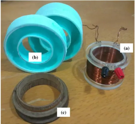
Figure 3.2 – Constitutive parts of the limiter. (a) Primary with configurable number of turns and an auxiliary winding for measurement of the linked flux. (b) Cryostats. (c) Superconducting secondary supported by a Celeron holder. ... 44
Figure 3.3 – Dimensions (in millimetres) of the magnetic core of the limiter. ... 45
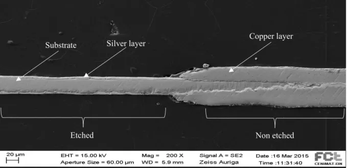
Figure 3.4 – Etched samples. (a) Front. (b) Back. The use of Kapton tape with adhesive (detached from the samples after etching procedure) provides protection of surfaces that should not be etched. ... 47
List of Figures
Figure 3.6 – Energy disruptive x-ray spectroscopy comparison between a copper-etched sample and a
virgin sample of SuperPower SCS4050 tape. Lα and Kα are x-ray levels of transition energies. ... 48
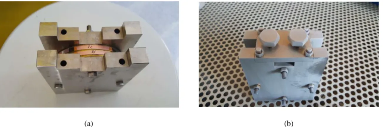
Figure 3.7 – Stainless-steel holder for soldering of superconducting rings. a) Interior detail with two tapes wound. b) Assembled device prepared for soldering. ... 49
Figure 3.8 – Celeron holder supporting superconducting rings. ... 49
Figure 3.9 – Illustration of a tape with voltage taps for four points method measurement. ... 51
Figure 3.10 – Experimental four points method. ... 52
Figure 3.11 – U-I characteristic of a 4 mm wide SuperPower SCS 4050 sample. Voltage points are spaced 12.6 cm from each other. According to the 1 µV/cm criterion, 12.6 µV is the critical voltage drop... 52
Figure 3.12 – Resistivity of superconducting layer as a function of temperature. ... 54
Figure 3.13 – Resistivity of layers as a function of temperature. ... 55
Figure 3.14 – Thermal conductivity of layers as a function of temperature... 56
Figure 3.15 – Volumetric heat capacity of layers as a function of temperature. ... 57
Figure 3.16 – Heat transfer coefficient as a function of temperature difference between the surface of superconducting tape and liquid nitrogen. A-B: Convective boiling. B-C: Nucleation boiling. C-D: Transition boiling. D-E: Film boiling. ... 58
Figure 3.17 – Diagram of the experimental assembly for the determination of the characteristic of the primary in the absence of the superconducting element. In order to take into account the leakage reactance, the auxiliary winding is wound around the primary, therefore in the same limb. ... 59
Figure 3.18 – Characteristic of the primary in the absence of the superconducting element. ... 61
Figure 3.19 – Measurement of the maximum amplitude of the current in the superconducting ring (a) Equivalent circuit. (b) Experimental apparatus. ... 62
Figure 3.20 – Measured magnetomotive force in the primary and induced current in the secondary as a function of time in the absence of magnetic core. Current in the secondary saturates nearly on the same values for different amplitudes of magnetomotive forces. ... 63
Figure 3.21 – Maximum hysteresis loop of the fault current limiter. ... 63
List of Figures
Figure 3.23 – Current in the superconducting coated conductor as a function of the magnetomotive force
developed in the primary. ... 66
Figure 3.24 – Peak current in the superconducting ring as a function of short-circuit time for five different cases of prospective line currents. ... 67
Figure 3.25 – Comparison between the empirical model of the current amplitude in the superconducting ring as a function of the primary magnetomotive force amplitude and experimental results, occurring in the first cycle of the short-circuit. ... 68
Figure 4.1 – Simulink simulation circuit. ... 72
Figure 4.2 – Simulink FCL model architecture. ... 73
Figure 4.3 – Simulink logic block. ... 74
Figure 4.4 – Simulink limiting current determination block. ... 74
Figure 4.5 – Simulink current control block. ... 75
Figure 4.6 – Equivalent circuit for determination of the current in each layer. ... 76
Figure 4.7 – Thermal-electrical analogy for thermal behaviour prediction ... 77
Figure 4.8 – Simultaneous electromagnetic and thermal computation flow diagram of the reverse engineering methodology. Thick arrows represent the main process cycle. Thin arrows correspond to input and output of the allocated variables. ... 78
Figure 4.9 – Simulation grid with the FCL in series with the line. ... 79
Figure 4.10 – Line current for different prospective line current scenarios. ... 80
Figure 4.11 – Primary linked flux for different prospective line current scenarios. ... 81
Figure 4.12 – Hysteresis loop for different prospective line current scenarios. ... 82
Figure 4.13 – Superconducting current for different prospective line current scenarios. ... 82
Figure 4.14 – Comparison between temperatures in each layer of the superconductor concerning simulation scenario 5. ... 83
Figure 4.15 – Temperature in superconductor for different prospective line current scenarios. ... 84
Figure 4.16 – Temperature in superconductor for different prospective line current scenarios. ... 84
Figure 4.17 – Convection dependence of the temperature in superconductor concerning scenario 5. . 85
Figure 4.18 – Convection dependence of the temperature in superconductor concerning simulation scenario 5. ... 85
List of Figures
Figure 5.2 – Test grid with the FCL in series with the line. ... 88
Figure 5.3 – Schematic diagram of the test bench. The auxiliary winding, represented in the same limb of the superconducting ring for diagram simplification, is wound around the primary to consider the leakage reactance. ... 89
Figure 5.4 – Laboratory apparatus during experiments. ... 90
Figure 5.5 – Experimental details of the temperature and current sensors. The cryostat, Celeron holder and a part of the iron core are also shown. (a) Diagram. (b) Real apparatus. ... 90
Figure 5.6 – Differential amplifier for signal conditioning of voltage measurements. ... 91
Figure 5.7 – Developed GUI for data logging from the data acquisition board National Instruments-6008 and digital multimeter Keithley-2001. ... 92
Figure 5.8 – Rogoswski coil with superconducting tape inserted. ... 93
Figure 5.9 – Silicon diode connection to digital multimeter in two-wire configuration. ... 94
Figure 5.10 – Precision 10 µA current source. ... 95
Figure 5.11 – Temperature response curve of the DT-670 silicon diode in the range 75 – 95 K. ... 95
Figure 5.12 – Comparison between simulation and experimental results of the line current... 96
Figure 5.13 – Comparison between simulation and experimental results of the primary linked flux. .. 97
Figure 5.14 – Comparison between simulation and experimental results of the hysteresis loop. ... 98
Figure 5.15 – Comparison between simulation and experimental results of the superconducting current. ... 99
Figure 5.16 – Comparison between simulation and experimental results of the temperature in the tape. ... 100
Figure A.1 – Dimensions, in mm, of the Celeron holder. ... 121
Figure A.2 – Dimensions, in mm, of the cryostat. ... 122
Figure C.1 – Dimensions, in mm, of the base piece of the stainless-steel holder (not to scale)... 125
Figure C.2 – Dimensions, in mm, of the top piece of the stainless-steel holder (not to scale)... 126
Figure C.3 – Dimensions, in mm, of the pressure piece of the stainless-steel holder (not to scale). .. 127
Figure D.1 – Comparison between simulation and experimental results of the line current for a prospective short-circuit current of 40.2 A... 129
List of Figures
List of Figures
List of Tables
List of Tables
List of Symbols
List of Symbols
Symbol Meaning
𝐴 Surface area (m2) or cross section area (m2) or value of magnetomotive force (A·t)
𝐴𝐶𝑜𝑛𝑣 Surface area subjected to convection (m2)
𝐴𝑓 Constant of the auxiliary sinusoidal function (A)
𝐴𝑘 Surface area of heat exchange of layer 𝑘 (m2)
𝑎 Geometrical parameter in four points method (m)
𝑎0 Fitting parameter in the methodology based on the maximum hysteresis loop (H)
𝐵 Flux density (T) or value of magnetomotive force (A·t)
𝐵𝑓 Constant of the auxiliary sinusoidal function (A-1)
𝑏 Geometrical parameter in four points method (m)
𝑏0 Fitting parameter in the methodology based on the maximum hysteresis loop (H)
𝐶 Heat capacity (J·K-1) or value of magnetomotive force (A·t) or capacitance (F)
𝐶𝐴𝑔(𝑖) Volumetric heat capacity of inner layer of silver (J·m-3·K-1) or capacitance
representing the volumetric heat capacity of inner layer of silver (F)
𝐶𝐴𝑔(𝑜) Volumetric heat capacity of outer layer of silver (J·m-3·K-1) or capacitance
representing the volumetric heat capacity of outer layer of silver (F)
𝐶𝐶𝑢(𝑖) Volumetric heat capacity of inner layer of copper (J·m-3·K-1) or capacitance
representing the volumetric heat capacity of inner layer of copper (F)
𝐶𝐶𝑢(𝑜) Volumetric heat capacity of outer layer of copper (J·m-3·K-1) or capacitance
representing the volumetric heat capacity of outer layer of copper (F)
𝐶𝐻𝑎𝑠𝑡 Volumetric heat capacity of Hastelloy (J·m-3·K-1) or capacitance representing the
volumetric heat capacity of Hastelloy (F)
𝐶𝑌𝐵𝐶𝑂 Volumetric heat capacity of YBCO (J·m-3·K-1) or capacitance representing the
volumetric heat capacity of YBCO (F)
𝐶𝑘 Capacitance representing the volumetric heat capacity of layer 𝑘 (F)
𝑐 Geometrical parameter in four points method (m) or specific heat capacity (J·kg-1·K-1)
List of Symbols
𝑐𝑘 Specific heat of layer 𝑘 (J·kg-1·K-1)
𝐷 Value of magnetomotive force (A·t)
𝑑 Geometrical parameter in four points method (m)
𝑑0 Fitting parameter in the methodology based on the maximum hysteresis loop ((A·t)-1)
𝑑𝑘 Mass density of layer 𝑘 (kg·m-3)
𝐸 Electrical field (V∙m-1) or scaling factor of current
𝐸𝐶 Critical electrical field (V∙m-1)
𝐸% Error between simulation and experimental results (%)
𝑒 Geometrical parameter in four points method (m)
𝐹 Scaling factor of current
𝑓 Frequency (Hz) or auxiliary sinusoidal function (A)
𝐺 Scaling factor of current
𝐻 Magnetic field (A·m-1) or scaling factor of current
ℎ0 Parameter for calculation of the convective heat transfer coefficient
ℎ1 Parameter for calculation of the convective heat transfer coefficient
ℎ2 Parameter for calculation of the convective heat transfer coefficient
ℎ3 Parameter for calculation of the convective heat transfer coefficient
ℎ4 Parameter for calculation of the convective heat transfer coefficient
ℎ5 Parameter for calculation of the convective heat transfer coefficient
ℎ𝐶𝑜𝑛𝑣 Convective heat transfer coefficient (W·m-2·K-1)
ℎ𝐶𝑜𝑛𝑣(𝑖) Convective heat transfer coefficient of inner surface (W·m-2·K-1)
ℎ𝐶𝑜𝑛𝑣(𝑜) Convective heat transfer coefficient of outer surface (W·m-2·K-1)
𝐼 Current amplitude (A)
𝐼0 Current fitting parameter (A)
𝐼1 Amplitude of the current in primary (A)
𝐼2,𝑝 Maximum amplitude of the superconducting current (A)
List of Symbols
𝐼𝑆𝐶 Short-circuit current of a grid (A)
𝐼𝑙% Limiting capacity (%)
𝐼𝑝1 Current fitting parameter (A)
𝐼𝑝2 Current fitting parameter (A)
𝐼𝐻𝑇𝑆∗ Maximum induced current in the superconducting element for which line current is
not limited (A)
𝑖1 Current in primary (A)
𝑖2 Induced current in superconducting ring (A)
𝑖2,𝐹 Current in secondary during fault operation (A)
𝑖2,𝑁 Current in secondary during normal operation (A)
𝑖𝐴𝑔(𝑖) Current in inner layer of silver (A)
𝑖𝐴𝑔(𝑜) Current in outer layer of silver (A)
𝑖𝐶𝑢(𝑖) Current in inner layer of copper (A)
𝑖𝐶𝑢(𝑜) Current in outer layer of copper (A)
𝑖𝐻𝑎𝑠𝑡 Current in Hastelloy (A)
𝑖𝐿 Line current (A)
𝑖𝑌𝐵𝐶𝑂 Current in YBCO (A)
𝑖𝑙 Limited current (A)
𝑖𝑝 Prospective current (A)
𝑖𝑘 Current of layer 𝑘 (A)
𝐽 Current density (A∙m-2)
𝐽𝐶 Critical current density (A∙m-2)
𝑘 Thermal conductivity (W∙m-1∙K-1)
𝑘𝐴𝑔 Thermal conductivity of silver (W·m-1·K-1)
𝑘𝐶𝑢 Thermal conductivity of copper (W·m-1·K-1)
𝑘𝐻𝑎𝑠𝑡 Thermal conductivity of Hastelloy (W·m-1·K-1)
List of Symbols
𝑘𝑘 Thermal conductivity of layer 𝑘 (W·m-1·K-1)
𝐿 Inductance (H)
𝐿1 Inductance of primary (H)
𝐿2 Inductance of secondary (H)
𝐿𝑀 Mutual inductance (H)
𝑙 Mean magnetic path length (m)
𝑙𝑘 Length of layer 𝑘 (m)
𝑚 Mass of a material (kg)
𝑁 Transform ratio
𝑁1 Number of turns of primary
𝑁2 Number of turns of secondary
𝑁𝐴𝑢𝑥 Number of turns of auxiliary coil
𝑛 𝑛-index
𝑃𝐴𝑔(𝑖) Current representing heat generated in inner layer of silver (A)
𝑃𝐴𝑔(𝑜) Current representing heat generated in outer layer of silver (A)
𝑃𝐶𝑢(𝑖) Current representing heat generated in inner layer of copper (A)
𝑃𝐶𝑢(𝑜) Current representing heat generated in outer layer of copper (A)
𝑃𝐻𝑎𝑠𝑡 Current representing heat generated in Hastelloy (A)
𝑃𝑌𝐵𝐶𝑂 Current representing heat generated in YBCO (A)
𝑃𝑘 Current representing heat generated in layer 𝑘 (A)
𝑄 Amount of heat (J)
𝑄̇𝐶𝑜𝑛𝑑 Rate of conduction heat flow (J·s-1)
𝑄̇𝐶𝑜𝑛𝑣 Rate of convection heat flow (J·s-1)
𝑅 Resistance (Ω)
𝑅1 Resistance 1 of signal conditioning (Ω) or resistance of primary (Ω)
𝑅2 Resistance 2 of signal conditioning (Ω) or resistance of secondary (Ω)
List of Symbols
𝑅4 Resistance 4 of signal conditioning (Ω)
𝑅𝐶𝑜𝑛𝑣(𝑖) Electrical resistance representing the convective heat exchange with liquid nitrogen
in inner surface (Ω)
𝑅𝐶𝑜𝑛𝑣(𝑜) Electrical resistance representing the convective heat exchange with liquid nitrogen
in outer surface (Ω)
𝑅𝑒,𝐴𝑔(𝑖) Electrical resistance of inner layer of silver (Ω)
𝑅𝑒,𝐴𝑔(𝑜) Electrical resistance of outer layer of silver (Ω)
𝑅𝑒,𝐶𝑢(𝑖) Electrical resistance of inner layer of copper (Ω)
𝑅𝑒,𝐶𝑢(𝑜) Electrical resistance of outer layer of copper (Ω)
𝑅𝑒,𝐻𝑎𝑠𝑡 Electrical resistance of Hastelloy (Ω)
𝑅𝑒,𝑌𝐵𝐶𝑂 Electrical resistance of YBCO (Ω)
𝑅𝑡,𝐴𝑔(𝑖) Thermal resistance of inner layer of silver (Ω)
𝑅𝑡,𝐴𝑔(𝑜) Thermal resistance of outer layer of silver (Ω)
𝑅𝑡,𝐶𝑢(𝑖) Thermal resistance of inner layer of copper (Ω)
𝑅𝑡,𝐶𝑢(𝑜) Thermal resistance of outer layer of copper (Ω)
𝑅𝑡,𝐻𝑎𝑠𝑡 Thermal resistance of Hastelloy (Ω)
𝑅𝑡,𝑌𝐵𝐶𝑂 Thermal resistance of YBCO (Ω)
𝑅𝑡,𝑘 Thermal resistance of layer 𝑘simulating conduction (Ω)
𝑆 Cross section area of magnetic core (m2)
𝑇 Temperature (K)
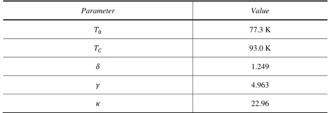
𝑇0 Temperature of liquid nitrogen (77.3 K)
𝑇𝐴𝑔(𝑖) Temperature of inner layer of silver (K)
𝑇𝐴𝑔(𝑜) Temperature of outer layer of silver (K)
𝑇𝐶𝑢(𝑖) Temperature of inner layer of copper (K)
𝑇𝐶𝑢(𝑜) Temperature of outer layer of copper (K)
𝑇𝐷 Measured temperature from silicon diode (K)
List of Symbols
𝑇𝐿𝑁2 Temperature of liquid nitrogen (K)
𝑇𝑌𝐵𝐶𝑂 Temperature of YBCO (K)
𝑇𝑘 Temperature of layer 𝑘 (K)
𝑡 Time (s)
𝑡𝑆𝐶 Instantaneous time after short-circuit (s)
𝑡𝑘 Sample 𝑘 of discrete time (s)
𝑈 Voltage drop (V)
𝑈𝐶 Critical voltage drop (V)
𝑢1 Voltage drop at the primary (V)
𝑢𝐴𝑢𝑥 Voltage drop of auxiliary coil (V)
𝑢𝐹𝐶𝐿 Voltage drop at the terminals of the fault current limiter (V)
𝑢𝐺𝑟𝑖𝑑 Grid voltage (V)
𝑣0 Output voltage (V)
𝑣1 Terminal 1 of input voltage (V)
𝑣2 Terminal 2 of input voltage (V)
𝑣𝐷 Voltage drop at terminals of silicon diode (V)
𝑥𝐸𝑥𝑝 Experimental quantity (A or Wb or K)
𝑥𝑆𝑖𝑚 Simulated quantity (A or Wb or K)
𝛾 Fitting parameter
𝛿 Fitting parameter
𝜅 Fitting parameter
𝜆𝑎 Ascending branch of linked flux (Wb)
𝜆𝑑 Descending branch of linked flux (Wb)
𝜌 Resistivity (Ω∙m)
𝜌0 Additional resistivity (Ω∙m)
𝜌𝐴𝑔(𝑖) Electrical resistivity of inner layer of silver (Ω∙m)
List of Symbols
𝜌𝐶𝑢(𝑖) Electrical resistivity of inner layer of copper (Ω∙m)
𝜌𝐶𝑢(𝑜) Electrical resistivity of outer layer of copper (Ω∙m)
𝜌𝐻𝑎𝑠𝑡 Electrical resistivity of Hastelloy (Ω∙m)
𝜌𝑌𝐵𝐶𝑂 Electrical resistivity of YBCO (Ω∙m)
𝜌𝑌𝐵𝐶𝑂,𝑁 Electrical resistivity of YBCO in normal state (Ω∙m)
𝜌𝑌𝐵𝐶𝑂,𝑆 Electrical resistivity of YBCO in superconducting state (Ω∙m)
𝜌𝑘 Electrical resistivity of layer 𝑘(Ω·m)
𝜏1 Time constant parameter (s)
𝜏2 Time constant parameter (s)
𝜓0 Linked flux with the primary in a magnetic core without secondary (Wb)
𝜓𝐹𝐶𝐿 Primary linked flux of a fault current limiter (Wb)
∇𝑇 Thermal gradient (K·m-1)
∆𝑇 Temperature variation (K)
List of Acronyms
List of Acronyms
Acronym Meaning
(RE)BCO Alloy of rare-earth element with barium-copper-oxide 1G First generation superconducting material
2G Second generation superconducting material
ABB Asea Brown Boveri Company
AC Alternating current
APER Aperture
Bi-2212 Bismuth-strontium-calcium-copper-oxide, Bi2Sr2CaCu2O8+x Bi-2223 Bismuth-strontium-calcium-copper-oxide, (Bi,Pb)2Sr2Ca2Cu3O10-x
BLCO Barium-lanthanum-copper-oxide
BSCCO Bismuth-strontium-calcium-copper-oxide
CLiP Current limiting protector
CNC Computer numeric machine
CRIEPI Central Research Institute of the Electric Power Industry
DC Direct current
DIG Digits
EMTP Electromagnetic Transient Program
FCL Fault current limiter
FEM Finite element modelling
GTO Gate turn-off thyristor
GUI Graphical user interface
HBCCO Mercury-barium-calcium-copper-oxide
HTS High-temperature superconductivity or high-temperature superconducting
IBAD Ion beam assisted deposition
IEEE Institute of Electrical and Electronics Engineers
List of Acronyms
IGBT Insulated-gate bipolar transistor
iSFCL Inductive superconducting fault current limiter from Bruker
LTS Low-temperature superconductivity or low-temperature superconductor MagLev Magnetic levitation
MOCVD Metal organic chemical vapour deposition
MRI Magnetic resonance imaging
NPLC Number of power line cycles
RTD Resistance temperature detector
rms Root-mean-square
S/N Superconducting/normal transition
SEM Scanning electron microscopy
SFCL Superconducting fault current limiter
SFCLT Superconducting fault current limiter-transformer SMES Superconducting magnetic energy storage
TBCCO Thallium-barium-calcium-copper-oxide
TSMG Top-seeded melt growth
Introduction
1
Introduction
The increased penetration of distributed power generation in electrical distribution and transmission power grids generally leads to higher fault current levels. To cope with such fault current levels, besides the topological measures based on splitting into sub-grids or busbars, there are several devices such as high voltage fuses, pyrotechnic breakers, air-core reactors and power electronic circuit breakers. However, these conventional measures and devices present some drawbacks as the case of the permanent increase of the impedance not only at fault operation regime but also at nominal operation regime. For these reasons, fault current limiters (FCLs) based on superconducting materials have been developed, in which superior performance can be achieved in comparison with conventional current limiting devices. Features such as negligible impedance at nominal conditions, fast and effective current limitation, and fast and automatic recovery after a fault can be accomplished by superconducting FCLs [1].
Superconducting materials, especially those based on ceramic oxides, are currently under intense research and development (R&D) and their recent developments show potential viability for practical applications in power systems due to excellent electrical and magnetic properties of such developed materials. On the one hand, the replacement of conventional conductors by superconductors in electrical equipment, such as cables, transformers and machines, provides lower losses in the electrical systems and, on the other hand, emerging devices are appearing without any counterpart in the conventional electrical devices, such as FCLs, which can help to mitigate several faulty operation problems in electrical grids [2].
Inductive FCLs, such as transformer type, are considered as emerging devices that provide technology for electrical grids, helping to mitigate several operational problems that such grids can experience as well as preventing the upgrade of the equipment.
This work addresses the topic of FCLs which is an evolving topic in the field of electrical grids. Before real application of FCLs in distribution electrical grids, several problems need to be investigated whereby this document presents a contribution to the study of these type of FCLs, addressing the design, modelling and experimental assessment of an inductive type FCL prototype.
Introduction
1.1
Background and Motivation
The emergence of distributed generation triggered the connection of new power plants to transmission and distribution networks which consequently leads to an increased risk of steady-state overload and potential of short-circuit occurrences. Strengthening the grid with new parallel routes contributes to mitigating steady-state overload but not for short-circuit faults whereby additional measures should be taken into account [1], [3], [4].
Electrical power protections are designed to maintain power networks highly reliable and fault-safe, contributing to cost savings and operational optimisation of such networks. It is very common the oversizing of such equipment to cope with faults, especially those based on short-circuit occurrences, whose values may highly exceed the nominal ones by a factor of 100 or higher [5]. However, oversizing electrical power protections tends to be expensive.
Besides protective relays and circuit breakers, classical measures to ease fault occurrences in the power system relies on the use of artificial rising resistances and/or inductances, such as air-coil reactors, or high stray impedance of transformers and generators. Topological measures, such as splitting the grid by reducing the number of sources that could feed a fault, constitutes other option but with significant investment costs and loss of interconnectivity. Fuses and pyrotechnic breakers are also considered measures, however, replacement is needed after a fault suppression and current flow is interrupted in the affected path [6].
It is required a more effective way to limit the consequences of fault occurrences and maintain the power system optimised during normal regime operation. Such desired characteristics can be found in FCLs. Ideally, an FCL is a device that does not affect the power system during normal conditions but during a fault imposes very quickly a high resistance and/or inductance that limits surge currents. This device can be installed in almost all locations of the power system.
Due to their electric and magnetic properties, HTS materials may be used in the development of current limiters. Generally, the principle of operation of these devices is based on the superconducting/normal (S/N) transition of HTS materials as well as the magnetic core saturation effect [7]–[9], although wide developed topologies where there is no transition also exist.
The key requirements of an FCL are:
▪ Insignificant resistance and inductance under normal unfaulted operation regime hence negligible influence on a power system.
▪ Detection and response to all short-circuit fault occurrences in a short period of time.
Introduction
▪ Automatic and quick recovery after a fault clearance.
▪ Reliable successive limitation of faults without damage.
▪ Negligible harmonics introduction in the power system during normal operation.
▪ No adverse impact on power system protective devices.
Among all different topologies of FCLs, the resistive and inductive types are the most mature. The resistive limiter is the one that has been most developed [10]–[12]. This topology uses an HTS material in series with the line circuit and uses the transition S/N to limit short-circuit currents. Its design is potentially the most compact, however, the need for current leads results in losses even during normal operation. On the other hand, inductive FCLs require an iron core which makes them relatively heavy but they exempt current leads. Besides, they require less amounts of superconductor and are robust against hot-spot formation [13]. The inductive type limiter is considered in this work.
1.2
Research Problem
The discovery of high-temperature superconducting (HTS) materials, in 1986, allowed the emergence of several power applications impacting, for example, power quality, limitation of faulty operation occurrences and weight and volume of equipment.
The FCL of inductive type is foreseen as an enabling technology for electrical grids, including dispersed, embedded or distributed generation. FCLs present themselves as attractive devices to protect such grids due to their inherent ability to limit short-circuit levels.
The interest in inductive type FCLs has increased due to the development of HTS tapes allowing to overcome design limitations found in FCLs based on HTS bulk materials, such as reduced size and mechanical robustness. HTS tapes are currently under intense R&D in order to develop them with excellent electrical and mechanical properties such as large currents facing high magnetic fields, continuous long length fabrication, tensile strain and stress properties as well as joining and contact techniques.
The development of this work aims answering the following research question:
How can the properties of the constitutive parts of an inductive type FCL be taken into account to model, simulate and design such limiter?
The research question can be addressed considering the following hypothesis:
Introduction
1.3
Objectives
This work pursues the following objectives:
▪ Study and modelling of the properties of superconducting tapes concerning the inherent electromagnetic-thermal phenomena when operating as current limiter.
▪ Development of a fast simulation tool for transient prediction of the behaviour of the FCL operating in electrical grids subjected to short-circuit fault occurrences.
▪ Prototyping of a laboratory-scale FCL and experimental tests in a test electrical grid.
▪ Development of a graphical user interface (GUI) for data collection of experimental data, such as line current, primary linked flux, superconducting current and temperature in superconductor surface.
▪ Comparison between simulation and experimental results in order to validate simulation methodologies.
1.4
Outline of the Thesis
This thesis is structured into six main chapters, one chapter of references and four appendixes, in which its technical vocabulary is, as far as possible, in accordance with the international electrotechnical terminology, published in the International Standard IEC 600501.
A brief description of the topics covered in each main chapter is as follows:
▪ 1 – Introduction: Gives a general overview of the features of inductive type FCLs, addresses the background and motivation as well as the objectives to conduct the research.
▪ 2 – Literature Review: In this chapter, the types of faults and mechanisms to deal with them are summarised, with special focus on inductive type FCLs. Commercial superconducting materials, namely bulks and tapes, are presented and their properties addressed. Joining of superconducting tapes is also discussed. The most common simulation methodologies to predict the behaviour of inductive FCLs in electrical grids are presented and the development status of this type of limiters, in terms of prototypes, are assessed.
▪ 3 – Design and Modelling of the Inductive FCL: The necessary baseline to conduct this work is discussed in this chapter. The design of the constitutive parts of the developed prototype are presented. Modelling of electromagnetic-thermal dependent properties of the superconducting element, such as critical current density, 𝑛-value, resistivity, thermal conductivity, volumetric
Introduction
heat capacity and convective heat coefficient is carried out. The electromagnetic-thermal behaviour of the limiter (composed of all constitutive parts) is also modelled.
▪ 4 – Simulation of the Inductive FCL: The implemented simulation methodology, in Simulink, from Matlab, is described in this chapter. The results provided by this methodology, namely, the line current, primary linked flux, hysteresis loop, superconducting current and temperature in the surface of superconductor are presented for different prospective line current scenarios.
▪ 5 – Experimental Validation of Models: Simulation models are validated with experimental data in this chapter. The experimental details of the test setup (prototype, power equipment and measuring units) are presented and a comparison between simulation and experimental results is made.
▪ 6 – Conclusions: A general summary of the performed activities and corresponding conclusions, as well as the future work, are presented in this chapter.
1.5
Original Contributions
The original contributions of this work are related to design, modelling, simulation, prototyping and experimental testing. The main contributions are:
▪ Design:
o Design of a cryostat and a holder for superconducting rings. This design, focusing an easy assembly for experimental tests, allows to house the secondary (which is supported by the holder, made by Celeron) in an open bath of liquid nitrogen provided by the cryostat. The cryostat, made by extruded polystyrene, is inserted around a limb of the magnetic core of the limiter.
o Design of a holder for soldering and development of superconducting rings. With this holder, made by stainless-steel, both terminals of superconducting tape segments are soldered with a specific curvature, in order to build short-circuited rings that wound the magnetic core of the limiter.
▪ Modelling:
Introduction
▪ Simulation:
o Development of a fast simulation tool for transient prediction of the electromagnetic-thermal behaviour of the limiter operating in electrical grids subjected to fault occurrences. The developed tool, implemented in Simscape Power Systems from Simulink/Matlab, extends a previously developed one that only considered the electromagnetic behaviour of the limiter, by adding a block that predicts the current and temperature in the superconducting secondary of the limiter. With this tool, the fault current limiter is inserted in electrical grids and subjected to fault occurrences where line current, primary linked flux as well as current and temperature in superconducting secondary are predicted. With the developed tool, simulations considering long-term short-circuit faults (e.g., 2 seconds) take less than 5 minutes of computation time.
▪ Prototyping:
o Prototyping of a laboratory-scale fault current limiter. The limiter is composed of a closed two-legged magnetic core, a primary winding made by copper wire and a short-circuited superconducting secondary, made by commercial superconducting tape, housed in a cryostat. Conceptually, the prototype is equivalent to a power transformer with a short-circuited secondary. This prototype is introduced in a test electrical grid subjected to short-circuit faults.
▪ Experimental testing:
o Development of a user interface for data logging from a data acquisition board (NI-6008) over USB interface and a digital multimeter (Keithley-2001) over IEEE-488 interface. This interface allows to start and stop data logging, of both measuring devices, at the same timestamps.
o Prototyping of a Rogowski coil for measuring the induced current in superconducting secondary. This coil is adapted to the reduced dimensions of the superconducting tape and cryostat. It is open ended and flexible, allowing it to be wound around the superconducting tape.
Introduction
1.6
Publications
The publications performed during the development of this work, [9], [14]–[20], are listed following:
▪ N. Vilhena, P. Arsenio, J. Murta-Pina, A. Pronto, and A. Alvarez, ‘A Methodology for Modeling
and Simulation of Saturated Cores Fault Current Limiters’, IEEE Transactions on Applied Superconductivity, vol. 25, no. 3, pp. 1–4, Jun. 2015. DOI: 10.1109/TASC.2014.2374179. ▪ N. Vilhena, P. Arsénio, J. Murta-Pina, A. G. Pronto, and A. Álvarez, ‘Development of a
Simulink Model of a Saturated Cores Superconducting Fault Current Limiter’, vol. 450, L. M.
Camarinha-Matos, T. A. Baldissera, G. Di Orio, and F. Marques, Eds. Cham: Springer International Publishing, 2015, pp. 415–422. DOI: 10.1007/978-3-319-16766-4_44.
▪ J. Murta-Pina, P. Pereira, J. M. Ceballos, A. Alvarez, N. Amaro, A. Pronto, J. Silva, and P.
Arsenio, ‘Validation and Application of Sand Pile Modeling of Multiseeded HTS Bulk
Superconductors’, IEEE Transactions on Applied Superconductivity, vol. 25, no. 3, pp. 1–5, Jun. 2015. DOI: 10.1109/TASC.2014.2366073.
▪ R. Ferreira, J. M. Pina, N. Vilhena, P. Arsénio, A. G. Pronto, and J. Martins, ‘Analysis of the Effects of Asymmetric Faults in Three-Phase Superconducting Inductive Fault Current
Limiters’, Journal of Physics: Conference Series, vol. 507, no. 3, p. 32036, May 2014. DOI: 10.1088/1742-6596/507/3/032036.
▪ P. Arsénio, N. Vilhena, J. Murta-Pina, A. Pronto, and A. Álvarez, ‘Design Aspects and Test of
an Inductive Fault Current Limiter’, Electrical, Control and Communication Engineering, vol. 5, no. 1, pp. 40–45, Jan. 2014. DOI: 10.2478/ecce-2014-0006.
▪ P. Arsénio, N. Vilhena, J. M. Pina, A. Pronto, and A. Álvarez, ‘Design Aspects and Test of a
Magnetic Shielding Inductive Fault Current Limiter’, in 14th International Symposium ‘Topical Problems in the Field of Electrical and Power Engineering’ and ‘Doctoral School of Energy and Geotechnology II’, 2014.
▪ P. Arsenio, T. Silva, N. Vilhena, J. M. Pina, and A. Pronto, ‘Analysis of Characteristic Hysteresis Loops of Magnetic Shielding Inductive Fault Current Limiters’, IEEE Transactions on Applied Superconductivity, vol. 23, no. 3, pp. 5601004–5601004, Jun. 2013. DOI: 10.1109/TASC.2012.2235896.
▪ J. M. Pina, P. Pereira, A. Pronto, P. Arsénio, and T. Silva, ‘Modelling and Simulation of
Literature Review
2
Literature Review
This section introduces a comprehensive analysis of the classic and emerging fault current limiting technologies for electrical grid protection. The several types of faults and measures to mitigate those events are discussed. Following, superconducting materials for applications on current limitation, i.e. bulks and tapes, are presented. The thermal properties of superconducting tapes are presented and joining techniques of those tapes are characterised. Also in this chapter, simulation methodologies of inductive type FCL are discussed. Lastly, the development status of such FCLs are presented.
2.1
Faults and Protection of Electrical Grids
An electrical grid is an extremely complex system composed of several equipment and lines separating producers and consumers. As any complex system, it is subjected to fault occurrences leading to possible abnormal regimes of operation. Due to such occurrences, fault limiting technologies are employed in order to provide higher robustness against faults thus avoiding or mitigating damaging consequences.
2.1.1
Types of Faults
Due to several reasons, electrical failures can occur in the power system equipment which leads to an abnormal regime of operation causing short-circuit currents or interruption of current flow. In a 3-phase electrical grid, faults can occur between phases, between phases and earth, or both. According to [21], a single phase-to-ground fault is the most common fault in power systems, making up about 70% to 80% of fault occurrences. In another reference, single phase-to-ground is pointed to be more than 90% [22].
Fault occurrences in power systems are practically inevitable. The main causes of faults are due to failure of joints on cables, failure of circuit breakers or weather factors, such as lightning strikes, accumulation of snow or ice, heavy rain, strong winds, floods and fires, falling trees or animals [23]. The current generated under these faults can exceed 100 times the rated current of the grid [24].
Power system faults are the result of abnormalities, which involves failure in the power system equipment with respect to the parameters of the system, such as voltage, current, power or frequency. Faults can be shunt, series or combination of faults. Figure 2.1 illustrates the possible faults of a power system. A shunt fault is characterised by the flowing of current between the earth and one or more phases or between phases at the frequency of the power system. A series fault consists of unequal impedance
Literature Review
among phases, commonly caused by the interruption of, at least, one phase. A combination fault is the occurrence of a shunt and a series fault simultaneously [8], [23].
Power System Faults
Combination
Shunt Series Shunt Series
Earth Phase-Phase
3-Phase
2-Phase
3-Phase
2-Phase
1-Phase
High Resistance
3-Phase
2-Phase
1-Phase
Figure 2.1 – Power system faults. Adapted from IEC Electropedia 448-13-02.
2.1.2
Fault Current Protection
Short-circuit currents can be eased by recurring to the well-known topological measures based on splitting the grid into sub-grids, splitting of busbars or even building new substations. These measures solve almost all fault issues and ensure future growth, however, can be costly and time-consuming for utilities. Other possibilities to protect power systems against fault currents are based on devices, such as current limiting fuses, pyrotechnic breakers, air-core reactors and also power electronic based devices. Fuses began to be used many decades ago and are able to limit the current and isolate the faulted section. However, this kind of devices have non-negligible thermal losses in normal operation and after a fault lead to an interruption in the respective network branch and need to be replaced.
Literature Review
pyrotechnic breaker and thus cutting off the network branch since the fuse is also destroyed due to overcurrent flow. Therefore, this device also needs to be replaced by a new one after a fault occurrence. The air-core reactor constitutes another alternative. This device is self-activating and limits the current due to the voltage drop across its terminals. The impedance of the air-core reactor is linearly variable as a function of current but presents considerable impedance in normal operation.
Power electronic circuit breakers are also used for current limiting purposes. Thyristor controlled series compensators, as well as self-commutated solid state devices, like gate turn-off thyristors (GTO) and insulated-gate bipolar transistors (IGBT), are examples of power electronic based devices [6], [25]. Comparing FCLs to the traditional devices, besides the capability to limit higher currents, the normal losses during normal regime are lower and fast activation and recovery time can be achieved with FCLs. Disadvantages are related to the need for medium to large-sized devices and associated costs of development and maintenance. As depicted in Figure 2.2, there are several locations in the electrical grid where FCLs can be introduced. The main benefits of integrating FCL in the grid are [26]:
▪ Generator connection (1): An FCL in the generator connection reduces the short-circuits arising from the generator, lowering the short-circuit levels in the connected network.
▪ Power station auxiliaries (2): Generally, short-circuit levels of power station auxiliaries are high, which can be reduced by FCLs.
▪ Network coupling (3): Security of supply and reduction of disturbances between networks can be ensured by FCLs.
▪ Busbar coupling (4 and 5): By employing an FCL between busbar, higher interconnection is achieved without necessarily increasing the short-circuit levels. The same benefits as network coupling are expected.
▪ Shunting current limiting reactors (6): In normal operation, the FCL shunting current limiting reactor, provides a lower resistive path, improving losses.
▪ Transformer feeder (7 and 8): An FCL can be introduced to protect the transformer and subsequent devices or only subsequent devices. This can be performed in order to avoid upgrading of devices.
▪ Busbar connection (9): When feeding critical loads, the FCL can be introduced to protect such load against short-circuits and avoid changes in the network.
Literature Review
▪ Coupling local generation sources (11): When introducing new distributed generation units in the grid, their contribution to short-circuit levels can be reduced by using FCLs.
▪ Closing ring circuits (12): Using an FCL in ring circuits, lower losses and protection against short-circuit currents are guaranteed.
Figure 2.2 – Possible locations of FCLs in the electrical power grids. Adapted from [26].
The behaviour of the line current as a function of the different regimes of operation with and without an FCL is illustrated in Figure 2.3. A summary and comparison of the traditional current limiting approaches and FCLs in terms of losses during normal operation regime, recovery time after a fault, size and cost is shown in Table 2.1.
FCL FCL FCL FCL FCL FCL FCL FCL FCL FCL FCL FCL Transmission Network Distribution Network Distibution
Literature Review
Figure 2.3 – Line current behaviour subjected to different regimes of operation with and without an FCL.
Table 2.1–Comparison of traditional current limiting approaches with FCLs.
Technology Normal
Losses
Recovery
Time Size Cost
Fuse Low No recovery Small Low but needs
replacement
Pyrotechnic breaker Low No recovery Small High and needs
replacement
Air-core reactor High Moderately
fast Large Moderate
Power electronic breaker Low to
moderate Fast Small Moderate
Circuit breaker Low After
reclosing Small Moderate
Superconducting FCL of
inductive type Very low Fast
Medium to
large High
Superconducting FCL of
resistive type Very low
Moderately
fast Medium High
Cur
rent
Time
With SFCL Without SFCL
Normal operation Fault Recovery
𝑖𝑝
𝑖𝑙
𝑖𝑛
Literature Review
Considering fault current protection of electrical distribution grids, several criteria must be taken into account such as:
▪ Admissible short-circuit current.
▪ Recovery time after a fault.
▪ Time response to successive faults.
▪ Withstand time of the limiter during a long-term fault.
▪ Normal-regime voltage drop across FCL terminals.
In a 3-phase electrical circuit, faults can be symmetrical or asymmetrical, as depicted in Figure 2.4 and Figure 2.5, respectively. In symmetrical faults, which are 3-phase ground faults and 3-phase short-circuit faults, all the phases are affected. Asymmetrical faults include 2-phase ground faults, 2-phase short-circuit fault and single-phase ground fault.
Generation Load
3-phase ground fault
Generation Load
3-phase fault
Figure 2.4 –Types of symmetrical short-circuit faults in 3-phase systems.
Generation Load
2-phase ground fault
Generation Load
2-phase fault
Generation Load
Single-phase ground fault
Literature Review
The occurrence of short-circuit currents create thermal effects on conductors and equipment as well as mechanical effects, particularly excessive electromagnetic forces and mechanical stresses in line conductors, busbars and transformer windings, for instance [23].
2.2
Superconducting Materials for Applications on Current Limitation
The phenomenon of superconductivity was discovered in 1911 by Heike Kamerlingh Onnes when researching the electrical properties of mercury. Onnes had found that when mercury was cooled until 4.2 K, loses abruptly its electrical resistance to less than 10-6Ω, as depicted in Figure 2.6. This state of
matter was called by the discoverer as “(…) the state of superconductivity” [27]. Since then, several metals, alloys and compounds with superconducting properties have been discovered.
Superconducting materials have a set of particular electromagnetic properties. Under a certain critical temperature, their resistivity is negligible and the magnetic flux density is expelled from the material. This perfect diamagnetism is called Meissner effect, i.e. the exclusion of magnetic field from the core of the superconducting material.
<10-6Ω
4.20 Hg
4.30 4.40 4.50
4.10 4.00 0.0000 0.0005 0.0010 0.0015 0.0020 Temperature (K) R es is tan ce ( )
Figure 2.6 – Electrical resistance of mercury as a function of temperature, measured by Onnes. Adapted from the original
measurement of H. K. Onnes.
Literature Review
The development of superconductors operating at high temperatures constitutes an intense field of investigation [30]. For power applications, only HTS materials can be employed since only these are economically viable due to reduced cooling costs [31], [32].
Superconducting materials for applications in current limiters are commercially available under the form of bulks and tapes. Bulks, mostly made of YBCO, are obtained by a process known as top-seeded melt growth (TSMG) which consists in a method to fabricate single or multiple grain superconductors. The seeds, which act as nucleation centres, are placed on the top surface of YBCO compacted pellets and subjected to heat-treatment processes followed by melt texture growth heating cycles in order to meet the bulks. Unfortunately, the TSMG process is confined to small scale and simple material geometries [33]–[35].
In the case of tapes, most adequate for FCLs due to long length tape availability and mechanical robustness, the most common compounds are BSCCO, i.e. first generation (1G) tape, and YBCO, i.e. second generation (2G) tape. The latter are also known as coated conductors and are best suited for working on higher magnetic fields than 1G tapes. Therefore, coated conductors are best suited for inductive FCLs [36].
2.2.1
Bulks
Bulk materials have a wide set of applications, such as motors, generators, magnetic levitation (MagLev), and magnetic resonance imaging (MRI), due to the high magnetic fields that can be trapped. Examples of commercial bulks are shown in Figure 2.7. Despite the wide range of applications, bulks are susceptible to cracking due to irregular thermal expansion of their body and, therefore, long-term operation is compromised [37].
(a) (b)
Literature Review
2.2.2
Tapes
When compared to 1G tapes, 2G tapes take advantage of their improved properties, such as mechanical robustness, operation at higher magnetic field and critical current. For fault current limiting purposes, 2G conductors are also expected to recover after a high current flow more easily than 1G conductors [38]. These 2G coated conductors, as illustrated in Figure 2.8, are manufactured by a continuous process using thin film deposition techniques in order to apply the superconducting material on buffered metal substrates. The manufacturing steps include electroplating, sputtering, electro-polishing, ion beam assisted deposition (IBAD) and metal organic chemical vapour deposition (MOCVD).
The IBAD process consists of a sputtering of a stack of buffer layers that develops a texture for the superconductor material deposition. The MOCVD is the deposition of the superconductor, based on (RE)BCO materials. Further details concerning the manufacturing process can be found in [36], [39], [40].
Figure 2.8 – Configuration of SuperPower SCS4050 HTS coated conductor. From [41].
![Figure 2.2 – Possible locations of FCLs in the electrical power grids. Adapted from [26]](https://thumb-eu.123doks.com/thumbv2/123dok_br/16585072.738726/48.892.120.778.270.720/figure-possible-locations-fcls-electrical-power-grids-adapted.webp)