) 1 ( min
min
, i i
y x
P x y
d
i i
−
=
∏
≠
Performance of Rotated Constellation and Trellis Coded Modulation
with Channel State Information Errors :MIMO Systems
Sameru Sharma, Derick Engles and S.S. Pathak
Abstract--
Increasing need for high data ratetransmission and reliability of communication over fading channels using multiple transmit antennas has drawn attention to high spectral efficiency modulation schemes such as Quadrature Amplitude Modulation (QAM). With the aim of increasing the ‘Diversity Order’ of signal set we consider multidimensional rotated QAM constellation. Increasing diversity order ‘L’ is not the only design parameter, there are some other important parameters like minimum product
distance ‘dpmin’ and the product kissing number ‘τP’
which influence the system performance. In this paper, the suitable rotation has been worked out for Multidimensions using the 16QAM & 64QAM constellations and the corresponding kissing numbers have been checked. The combined architecture for MIMO (multiple- input multiple- ouput) Antenna system involving the concept of rotated constellation and concatenated with trellis coded modulation (TCM) is designed and simulated using the low complexity lattice decoder at the receiver. The performance of rotated and non-rotated constellation with Channel State Information (CSI) error has been evaluated.
Keywords -- CSI, Diversity, Multi Antenna,
QAM, TCM.
I. Introduction
Recently, the field of multi-antenna processing has attracted large interest in the communication community due to the huge capacity of the multi-antenna environment [10]. Generally MIMO techniques / algorithms aim at data rate maximization or diversity maximization, looking for performance enhancement. There are also limits set for the trade off viz. DMG trade off (Diversity – Multiplexing Gain) [1], [9]. The technique used to get closer to these theoretical capacity limits fall under the realm of space time coding (STC) [8]. To mitigate fading many communications systems use a space diversity.
The error probability of a multidimensional signal set is essentially dominated by four factors. To improve performance it is necessary to:
Manuscript received December 30, 2007.
Sameru Sharma is with Electronic & Communication Engineering Department, Govt. College of Engineering, Jammu, India. Tel: +91-191-2462370 (Email:[email protected])
Derick Angles is with Electronics Technology Department GND University, Amritsar, India. (Email:[email protected])
S.S. Pathak is with Electronics & Electrical Communication Department, Indian Institute of Engineering, Kharagpur, India. (Email:[email protected])
i) minimize the average energy per constellation point.
ii) Maximize the diversity L
iii) Maximize the minimum L-product distance.
iv) Minimize the product kissing number ‘τp’ for
the L-product distance i.e. the total number of points at the minimum L-Product distance. Boutros [3] have verified the diversity order ‘L’ & the minimum product distance, ‘dpmin’ and found that as
diversity increases the bit error rate curves approach the one for the Gaussian channel. But doubling of the diversity and dp min are not the only important design parameters to
increase the performance. In this paper, work has been carried for the third design parameter i.e. product kissing number. The product kissing number ‘τp’ is a critical
design parameter to improve performance.
The primary contribution will be evaluation of new algorithm approach for signal set design that achieves high level of diversity. Utilization of error control coding at the signaling stage of the constellation is apparently an alternative to improve the performance[2][4].
Lattices Code are used in digital transmission as high rate signal constellation. They are obtained by carving a finite number of points from an n-dimensional lattice in the eucilidean space. The lattice codes are effective because they present high modulation diversity L i.e. any two code vectors always differ in at least L coordinates[5][6][7]. The effort in this paper is to design a lower complexity lattice decoding algorithm. A new combined architecture for two antennas system involving the concept of rotated constellation and concatenated with Trellis Coded Modulation (TCM) is designed using the low complexity lattice decoder at the receiver and the performance of rotated and non rotated constellations has been evaluated. The essential part of the most of the MIMO Space Time Architecture is the need for the CSI at the receiver, so is the case with the architecture that has been presented in this paper.
II.
Diversity Multiplexing Tradeoff
The key point to increase the modulation diversity is to apply a certain rotation to a classical signal constellation in such a way that any two points achieve the maximum number of distinct components. In this paper, the rotated versions of a multi dimensional QAM constellation has been worked out and is as given below. A. Dimension 2
All two dimensional orthogonal matrices have the following structure:
) 3 (
2 1
1 2
4 ⎟⎟
⎠ ⎞ ⎜⎜ ⎝
⎛ −
= ⎟⎟ ⎟ ⎟ ⎟
⎠ ⎞
⎜⎜ ⎜ ⎜ ⎜
⎝ ⎛
− −
− −
− −
=
M M
M M
a b c d
b a d c
c d a b
d c b a
M
2 2
1
1
λ
+
=
U
a
2 2 2
1
λ
λ
+
=
U
b
U
d
U
c
λ
λ
λ
=
=
2 ⎟⎟ ⎠ ⎞ ⎜⎜ ⎝ ⎛ − =
a b
b a
M2 with the constraint a
2+b2=1
Parametrizing this orthogonal matrix as a function of single variable λ gives
2
1
/
1
+
λ
=
a
and b= λa. (2)By varying the λ value in steps of 0.005 and for each value computing all the product distances and picking the least of it, the dpmin has been plotted as a function of λ (fig.
1). From the graph in fig. 1, we pick the value of λ = 1.71 (maximum case). This leads to the rotation matrix for the 2 dimensional case as
⎟⎟
⎠
⎞
⎜⎜
⎝
⎛
−
=
50
.
0
86
.
0
86
.
0
50
.
0
2M
, the subscript 2 indicatingthat it is the 2 dimensional case. B. Dimension 4
The family of 4- dimensional orthogonal matrices
considered here is
where M2 (submatrix) is fixed as the optimal 2
dimensional matrix and its parameter is used (renamed as λ2). The other 2x2 submatrix M1 is dependent on the
parameter λ. The orthogonality constraint reduces to ad – bc =0. This gives rise to the following equations:
Where
2 2 2 2 2 2 2
λ
λ
λ
λ
λ
+
+
=
U
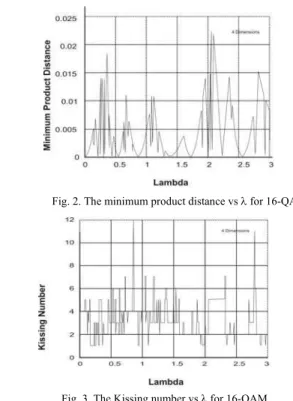
The minimum product distance variation and the kissing number plots are shown in fig. 2 and 3. From the plot, the value λ = 2.05 is the optimum parameter that gives dpmin =
.0222. The four dimensional rotation matrix (M=2 antennas & T=2 symbol periods and MT determines the dimension)
.
Fig. 3. The Kissing number vs λ for 16-QAM
may be constructed in a Hadamard way. The values of the rotation matrix have hence been computed as:- a = 0.2012, b= 0.33, c = 0.49, d = 0.79
Hence the rotation matrix become M4 = 0.2 0.33 - 0.49 - 0.79
-0.33 0.2 0.79 -0.49
0.49 0.79 0.2 0.33 (4)
-0.79 0.49 -0.33 0.2
This work involves the utilization of the 4 dimensional rotated constellation in a 2x2 antenna system.
Results
It has been verified that product kissing number ‘τP’ which
is a critical design parameter is equal to 1 for relevant ‘dpmin’ value. Simulation of multi dimensions were done to
arrive at the optimum rotation to maximize the diversity base on the criteria of maximization of the minimum product distance and minimization of the kissing number. It has been verified that the variation of the minimum product distance are same for higher constellation though the graphs are not included here.
III. Construction of the Rotated Constellation for
2 antenna system
System Model
Consider a system of M transmit N receive antennas. An space time (ST) modulation associates with each q x 1 information symbol vector s = (s1….,sq) from a
q-dimensional input constellation Sq, an M x T modulation
matrix
B
(
s
)
∈
ʗMxT, with ʗ the field of complex numbers, where M modulated symbols bmt
,
for m=1,….,M aretransmitted simultaneously from all transmit antennas at time t for t = 1,….,T.
The modulation B has a
Fig. 1. The minimum product distance vs λ for 16-QAM
)
9
(
W
uM
X
′′
=
H′+
′′
(
s
s
) (
B
s
s
) (
B
s
s
)
A
−
′
Δ
−
′
H−
′
(
)
(6)8 Pr 2 1 rN s N r j j E s s − − = ⎟⎟⎠ ⎞ ⎜⎜ ⎝ ⎛ ⎟⎟ ⎠ ⎞ ⎜⎜ ⎝ ⎛ ≤ ′ ⎯→ ⎯
∏
σ
λ
)
10
(
)
(
~
2 1 , 1 1 11 1 2 i x nT
q
S
z
T
d
=
−
+
−
transmission rate of q/T symbols per channel use (PCU). Let X be the N x T be received signal matrix, H be the N x M channel matrix, and W the N x T noise matrix. The received signal in matrix form, is :
X = HB + W (5)
Under quasi-static fading, assuming perfect CSI at the receiver, the pairwise error probability (PEP) of the ML detection of the information vector s′ knowing that the information vector s ≠ s′ has been transmitted is upper bounded by
Where Es is the average energy per symbol, n is the
minimum rank of the set of matrices B (s-s′) for all pairs of information vectors s ≠ s, and λj, j = 1....r, are the non-zero
eigenvalues of
with the subscript
H
denoting the conjugate transpose. Then minimizing the PEP is equivalent to the following criteria• The Rank Criteria : the minimum rank r of
B
(
s
−
s
′
)
taken over all distinct information vector pairs
( )
s
,
s
′
, is the diversity gain.• The Determinant Criterion : the minimum of geometric mean of the nonzero eigenvalues of
(
s
s
)
A
−
′
,
taken over all distinct pairs( )
s
,
s
′
is the coding gain and should be maximized.IV. Low complexity lattice decoder for rotated
Constellation with 2 Antenna System
Imposing of a lattice structure necessitates, rewriting of the rotated constellation presented in (5). The equivalent uncoded system is given by
h11 h12 0 0
Vec (XT) = 0 0 h11 h12
h21 h22 0 0 . Mp4sT + Vec (WT)
0 0 h21 h22
= HPMp4sT + Vec (WT) (7)
where hij refers to the fading components between the i th
receive and jth transmit antennas, Vec (XT) is the vector representation of the matrix XT (superscript T refers to
transpose) by putting all its columns one after another in one vector column. Mp4 is the rotation matrix M4 with the
third line multiplied by – 1, the received signal could be written as
X' = Vec (XT) = H'sT + W' (8) Where H' = HpMp4 of rank 4, since the rank of Hp is rank
4. Finally the lattice representation of the resulted system is given by
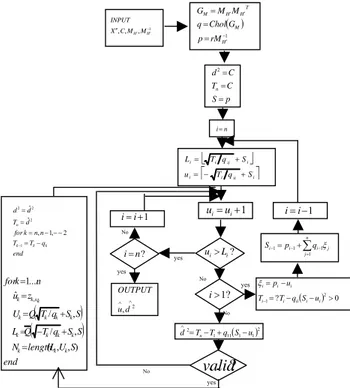
The dimension increase is from M = 2 → 2 x 2 x 2= 8 (2 Time slots and 2 antennas) Fig. 4 presents the flowchart of
low complexity lattice decoder algorithm. The Principle of the algorithm is to search the closest lattice point to the receive signal within a sphere of radius
C
centered at the receive signal. This guarantees that only the lattice points within the square distance C from the receive point are considered. This algorithm begins its search near the centre of the sphere. Each time a valid lattice point is found, the search is restricted further by reducing the radius of the sphere to be equal to the distance of the newly discovered lattice point from the sphere centre.The algorithm uses several specific functions and variable. The function Chol (GM) computes a normalized cholesky
factorization of the Gram matrix of MH (i.e. the Gram
Matrix is GM = MH′MTH′). The decomposition is of the form
GM = RR T
with R an upper triangular matrix with entries rij.
When a vector inside the sphere is found, the square distance between this vector and the receive vector (the centre) is given by :
This value is compared to the minimum square distance d2 (initially d2 =C) found so far in the search. If
2
ˆ
d
is smaller than d2 then we have a new candidate closest point and the search continues until all the vectors inside the sphere are tested. The variable d2 is the current squared radius of the sphere andu
ˆ
is the newly found lattice point. Wherever a valid lattice point x is found within the sphere, in addiction to reducing the current squared radius d2 so that the newly discovered lattice point lies on the surface of the sphere, the algorithm recomputes all the lower and upper bounds according to the new d2 value.
``
Fig. 4. Flow chart of the low complexity lattice decoder
1 , , , − ′ ′
′′CMHMH
X
INPUT ( )
1 − ′ ′ ′ = = = H M T H H M rM p G Chol q M M G ⎣ ⎦
⎡ i ii i⎤
i i ii i i S q T u S q T L + − = + = yes yes yes No yes n i= ∧ ∧ 2 ,d u OUTPUT
( ) 0
? 2
1= − − >
− =
− i ii i i
i i i i u S q T T u p ξ ? 1 > i 1 + =i
i ui=ui+1 i=i−1 ∑ = − − −= + n j j i i
i p q
S 1 1 1 1 ξ ? n
i= ui>Li?
( )2 1 1 11 1 2 u S q T T d=n− + −
( )
~( )
~( ) ( )
( )
( )
(11) 1l l v l c l T
p E l y
N
i
j j i ij s s
j
∑
=
+ + ′
= δ α η
V. Proposed System architecture
The proposed architecture is given in fig. 5. The input is a binary source, which goes through a TCM stage. This output is fed to the constellation mapper in sets of 4 symbols at a time. The constellation mapper (constellation rotation) provides a set of 4 symbols, which are transmitted through the two transmitters in two time slots. The channel is the Rayleigh fading channel and at the receiver there are two antennas which feed the received signals to the sphere decoder. The output of the sphere decoder is sent to the low complexity lattice decoder with trace back length of 3, whose output is the received bits.
VI. Simulation Results and Performance
Analysis
The proposed architecture was simulated in MATLAB environment and the performance was studied. The channel matrix H is assumed to be available at the receiver. The fading components of the matrix are modeled as complex Gaussain noise with variance of 0.5 per dimension; this gives rise to the Rayleigh fading channel. 10,00,000 input bits have been considered as input to the proposed architecture. Complex AWGN noise, i.e. the W matrix is added at the receiver so that the noise variance per dimension is given by 10-SNR/10. The choice of the radius for the sphere decoder, √C was varied as a function of SNR and the values were set by trail and error for the various SNR values. The curves in fig 6 represent the average bit error rate (BER) as a function of the SNR in dB at the receiver.
Fig. 7. Performance of architecture without Rotation with and without TCM stage
The curves in fig 6 represent the average bit error rate as a function of the SNR in dB at the receiver. The two plots in the graph correspond to the performance when only the rotation is used and when the rotation is concatenated with the TCM stage. The corresponding data rates of the two cases are 4 bits PCU and 2 bits PCU (Per Channel Use) respectively (since it is rate half convolutional coder). It may be noted that there is a 1.5 to 2 dB improvement in the performance of the system when the TCM stage is introduced. Lowering of BER suitably compensates the loss in capacity.
What has also been considered as a need for comparative study is to look at the performance of a similar architecture if no rotation is given. That is to have the rest of the architecture same and just replace the M4 matix
unrotated. This can be done by the choice as 1 0 0 0 0 1 0 0
M4 = 0 0 1 0
0 0 0 1
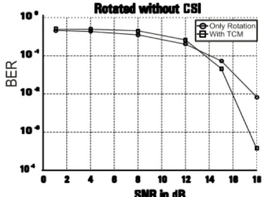
With this choice, the system shown in fig. 5 becomes an unrotated system. The performance of this system was also carried out on the similar lines and is shown in fig. 7. It is interesting to note that the performance of the unrotated constellation is poorer as compared to the rotated constellation architecture.
VII. Performance of the architecture with CSI
errors
There are estimation techniques [11] available to estimate the channel state at the receiver. However, it is always possible that the CSI estimates do have errors inherently and, this necessitates the study of any MIMO architecture under errors in CSI. In this paper the proposed system architecture is evaluated with errors in the estimated CSI. A Estimation Techniques
Consider N transmit, M receive antenna set up. We can write the received signal samples for the
l
th symbol within the burst at the optimum sampling instant asFig. 5. The proposed system architecture
Fig. 6 . Performance of architecture with Rotation TCM stage
Binary Source
TCM Constellation
Mapper
Fading Channel
Recei ved Bits
Lattice
decoder Sphere Decoder
AWGN
T
ransm
it
Div
ers
it
y
Recei
v
e D
iv
er
sit
y
[
P
1P
2...
P
]
~
( )
n
z
( )
n
(
13
)
A
s N j+
j=
α
( )
,
1
,
2
,...,
(
14
)
.
)
(
ˆ~
2 *
N
i
P
A
n
Y
P
l
i s
j i
ij
=
=
α
( )
~
(
)
(
)
(
15
)
ˆ~
n
n
e
n
ij ij ij
=
α
+
α
( )
( )
,
1
,
2
,...,
(
16
)
.
2*
N
i
P
A
l
z
P
n
e
i s
j i
ij
=
=
( )
(
17
)
.
2 2 2 2i s
o v e
P
A
N
n
=
σ
+
σ
)
18
(
99
.
0
1
1
1
⎟⎟
⎠
⎞
⎜⎜
⎝
⎛
=
H
where
( )
δ
T
s′
is the timing error after timing synchronization,η
j( )
l
is the AWGN with zero mean and variance2
o
N
per dimension, and
v
j( )
l
is the ISI due to the timing error which is modeled as uncorrelated Gaussian noise with zero mean and varianceσ
v2.α
~
ij( )
l
are the fading components to be estimated.
~
p
( )
l
is the pulse used for shaping andc
i( )
l
are the transmitted symbols. This scheme works on pilot symbols being transmitted from the transmitter.Consider output samples corresponding to thenth pilot
sequence within the burst
(
(n 1)Ls 1) (
,yj (n 1)Ls 2)
,...,yj(
(n 1)Ls Lp)
.y − + − + − + The
Channel is assumed to be constant over the duration of the pilot sequence and is equal to the value of the channel is the middle of the pilot sequence. Defining the overall noise term as:
( )
n
( )
n
v
( )
n
(
12
)
z
j=
η
j+
jWe define Yj (n) as
( )
[
( ) ( )(
)
]
Tp s j s j s j
jn y n L y n L y n L L
Y = ( −1) +1 ( −1) +2... ( −1) +
where
A
s=
E
sp
~
( )
δ
T
s′
. Using the fact that the pilot pulses P1, P2, …, PN are orthogonal, and each oflength LP, we can immediately see that the minimum mean
square error (MMSE) estimate of
α
~
ij( )
l
is given by:Where
.
denotes matrix norm. Hence, the estimation of the various fading components is done. It can also be noted thatwhere eij
(
n
)
is the estimation error due to the noiseand ISI given by
Since zj
(
n
)
is assumed to be zero mean Gaussianrandom vector we have that eij (n) is also Gaussian with
zero mean and variance
B Performance of the system with no CSI
Fig. 8. Performance of proposed architecture with no CSI at receiver
When the CSI is not known at the receiver the channel
matrix becomes
⎟⎟
⎠
⎞
⎜⎜
⎝
⎛
=
1
1
1
1
H
at the receiver. Though, the fading does take place, since the receiver is not aware of the fading component it is safe to assume as above. However, the problem faced with such a choice of H at the receiver is that this choice is not an orthogonal choice, because of which the Cholesky factorization of the corresponding Gram matrix cannot be performed. The lattice decoding algorithm requires that a Cholesky factorization be performed on the Gram matrix. A matrix has to be positive definite in order that a Cholesky factorization be done on it. In order to make this possible, we force a value other than 1 (but close to it) in one of the components of the H matrix. With this we have the matrix at the receiver as :This ensures that the corresponding Gram matrix is positive definite and hence Cholesky factorisable. The performance of such a system has been simulated and studied. The performance plot is shown in fig. 8. The performance plot of the nonrotated constellation without CSI is not attached because of its very poor performance. This performance can be compared with the case with perfect CSI to see the degradation in performance; however the TCM stage does come to the rescue of this case and keeps the BER under check at reasonably high SNR atleast. C. CSI with errors
When looking at the proposed system with CSI errors, we can model the errors in various ways, either as the errors dependent on the SNR or independent of the SNR. We have adopted the way of introducing errors in CSI independent of SNR. The errors in the 2x2 channel CSI,
⎟⎟
⎠
⎞
⎜⎜
⎝
⎛
∈
∈
∈
∈
22 21
12 11
are modeled here as zero mean complex Gaussian variables with variance of 0.01. Hence the overall CSI available at the receiver is
⎟⎟
⎠
⎞
⎜⎜
⎝
⎛
∈
+
∈
+
∈
+
∈
+
22 12 21 11
12 12 11 11
h
h
h
h
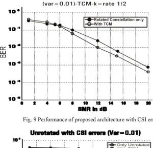
Fig. 9 Performance of proposed architecture with CSI errors
incorporated in all the 4 channels. Incorporating this error model in the receiver part of the system and carrying out the rest of the simulation as before, the performance plots were obtained. This was done for both the cases of rotated constellation as well as unrotated constellation. The results are in fig. 9 and fig. 10 respectively
VII. CONCLUSION
A new combined architecture for two antenna system involving the concept of rotated constellation and concatenated with TCM using the low complexity lattice decoder at the receiver has shown an improvement of 1 to 1.5 dB in the performance of the rotated constellation as compared to the unrotated constellation. The simulation studies have revealed that this architecture does provide a good performance improvement and better Bandwidth efficiency (2 symbol PCU) as well. Also suitable changes have been incorporated in the existing sphere decoder algorithm by way of adding a feedback mechanism in such a way that provides a huge decrease in complexity and gives rise to systems with high spectral efficiency. To realize the advantage of the proposed system, it was intuitively felt that the system should be evaluated under CSI estimation errors. The architecture was studied under CSI errors as well as the case when no CSI is available at
the receiver, which could happen in case of sudden burst errors wherein the receiver could make a decision that it will assume lack of CSI. This study has shown results wherein the new architecture provides much better performance to that of the nonrotated architecture. The TCM stage comes to show its usefulness in the case of absence of CSI at the receiver. This has justified the use of rotated constellation as well as the use of TCM stage adequately. Intuitively, one can suggest that the TCM stage will find its use in a much more pronounced manner in case of higher (denser) QAM constellation with more number of antennas.
REFERENCES
[1] A. Medles and D.T.M. Slock, “Achieving the optimal
Diversity – Versus – Multiplexing Trade off for MIMO Flat Channels with QAM Space – Time spreading and
DFE Equalization”, IEEE Trans. On Inform. Theory,
Vol. 52, No. 12 December 2006.
[2] V. Tarokh, N. Seshadri and A. Calderbank, “Space-time
codes for high data rate wireless communications:
Performance criterion and code construction,” IEEE
Trans. Inform. Theory, vol. 44, Mar. 1998, pp. 744-765.
[3] J. Boutros, E. Viterbo, “Signal space diversity: A power
and bandwidth efficient diversity technique for the
Rayleigh fading channel,” IEEE Trans. Inform. Theory,
vol. 44, July 1998, pp. 1453-1467.
[4] P. Garg, R.K. Malik and H.M. Gupta, “Performance
analysis of Space-time coding with imperfect channel estimation, “IEEE Trans. Wireless commun., Vol. 4, PP 257-265, Jan. 2005.
[5] M.O. Damen, A. Chkeif “Lattice Code Decoder for
Space – Time Codes”, IEEE Commun. Letters, Vol. 4,
No. 5, May 2000 pp 161-163.
[6] E. Viterbo and J. Boutros, “A Universal Lattice Code
Decoder for Fading Channels”, IEEE Trans. on Inform.
Theory, Vol. 45, No.5, July, 1999 pp 1639-1642.
[7] X. Zhu and R.D. Murch, “Performance analysis of
maximum likelihood detection in a MIMO antenna
system,” IEEE Trans. Commun., vol. 50, pp. 187-191,
Feb 2002.
[8] M.O. Damen, K. Abed-Meraim, and J.-C. Belfiore,
“Diagonal algebraic space-time block codes,” IEEE
Trans. Inform. Theory, vol. 48, pp. 628-636, Mar. 2002.
[9] G.J. Foschini and M.J. Gans, “On limits of wireless
communication in a fading environment when using
multiple antennas”, Wireless Personal Commun., vol. 6,
no. 3, pp. 311-335, 1998.
[10] A. Goldsmith, S.A. Jafar, N. Jindal and S. Vishwanath,
“Capacity Limits of MIMO Channel”, IEEE Journal on
Selected Areas in Commun., Vol. 21 No. 5 pp 684-702, June 2003.
[11] T. Kurt and H. Delic, “Space Time Coding and Signal Space Diversity in the presence of Channel Estimation
Errors”, Canadian Conference on Electrical and
Computer Engineering, 2004. Volume 1, 2-5 May 2004 Page(s): 273-276.