D. Ujwala et al Int. Journal of Engineering Research and Applications www.ijera.com
ISSN : 2248-9622, Vol. 4, Issue 3( Version 1), March 2014, pp.102-105
www.ijera.com 102 |P a g e
Wideband Coaxial Fed Rotated Stacked Patch Antenna for
Wireless Applications
D. Ujwala
1, A. Gnandeep Reddy
2, J. Kowsik Sasthre
2, K. Gopivasanth Kumar
2,
K. Sai Chandra
21
Assistant Professor, Department of ECE, K L University, Guntur Dt., A.P, India
2
Students, B. Tech, Department of ECE, K L University, Guntur Dt., A.P, India
Abstract
A novel circularly polarized coaxial fed rotated stacked patch antenna is proposed and its performance characteristics are presented in the current work. The antenna consisting of four parasitic patch, each one being
rotated by 300 relative to its adjacent patches. The proposed antenna is giving return loss less than -10 dB with
VSWR<2 and bandwidth 700 MHz (5.8 to 6.5 GHz) with axial ratio less than 3dB. The analysis of the antenna is explained through parametric study and HFSS simulation results are presented in the current work.
Keywords
: Coaxial Feeding Rotated Stacked Patch, Performance Characteristics.I.
Introduction
Miniaturization of microstrip patch antennas (MPAS) is a very challenging field to investigate due to the increasing interest in integrating such antennas in MMIC circuits. The conventional dimensions of MPAS are around a half waveguide wavelength. Several miniaturization techniques are appearing to reduce such dimensions. These techniques can be classified in: 1) Use of high permittivity substrates; 2) Use of magnetic substrates; 3) Increase electrical length; 4) Short-circuits; 5) Superstrates and 6) Combinations of them [1]. Using high permittivity substrates, the antenna size can be considerably reduced. One of the main problems is the wave mode excitation causing a reduction of surface-wave radiation efficiency. Moreover, as the substrate has finite dimensions, the diffracted field due to the surface-wave mode, degrades the radiation pattern increasing the side-lobe level and increasing also the cross polar field. In arrays, the mutual coupling caused by surface wave modes limits beam-steering [2].
One of the methods of generating circular polarization with broad AR bandwidths is the application of stacked multilayered patch structures.
In [3]–[5], various configurations of stacked patch
antenna structures have achieved dB relative bandwidths of 13.5%, 9.6%, and 13.5%, respectively. In [6], a microstrip antenna composed of an L-shaped feed network, a wide slot, and a parasitic patch has
obtained a bandwidth of 45% with a gain of 4 dBic. However, the antenna radiates in a bidirectional radiation pattern. Among microstrip antennas,
aperture stacked patch (ASP) antennas [7]–[10] are
appealing due to their wide-VSWR bandwidth. In this paper, a novel method is presented for the generation of circular polarization by a modification of an ASP antenna composed of four patches, each one being oriented at an angle of 30 with respect to its adjacent lower and upper patches. The advantages of the proposed antenna are its high gain, wide CP bandwidth, simple design, ease of fabrication, and appropriate geometry to be used in an array configuration.
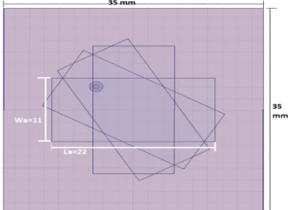
Fig 1 Coaxial Fed Rotated Stacked Patch Antenna
D. Ujwala et al Int. Journal of Engineering Research and Applications www.ijera.com
ISSN : 2248-9622, Vol. 4, Issue 3( Version 1), March 2014, pp.102-105
www.ijera.com 103 |P a g e
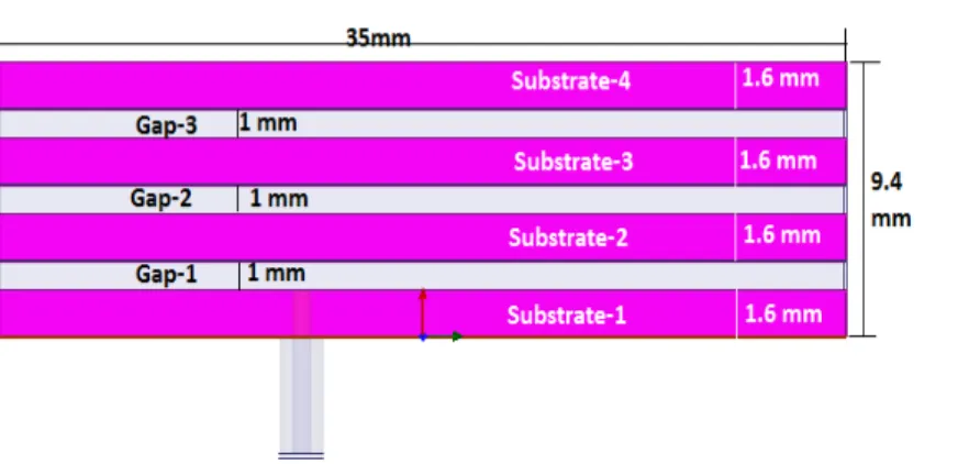
Fig 2 Side View of the Model
II.
Antenna Specifications
Fig 1 and 2 shows the proposed antenna model with rotated stacked patches and side view of the antenna.
The stacked patches are taken on FR4 substrate materials with separation of 1.6 mm thickness of each substrate. Table 1 shows the antenna specifications.
S. No Specification
1 4-Layers
2 All are FR-4 Substrates
3 3 air gaps
4 Patches are rotated 30 degrees consecutively
5 Feed location: (-5mm, 4mm)
6 Dimensions: 35mm x 35mm x 1.6mm
7 Patch dimensions: 22mm x11mm
III.
Results and Discussion
5.00 6.00 7.00 8.00
Freq [GHz] -40.00
-30.00 -20.00 -10.00 0.00
d
B(S
t(1
,1
))
stacked patch antenna
Return Loss ANSOFT
m1 m2
m3
m4 Curve Info dB(St(1,1)) Setup1 : Sw eep1 feedX='-5mm' feedY='4mm'
Name X Y
m1 5.8859 -10.3111
m2 7.5772 -10.1583
m3 6.1879 -35.0783
m4 7.2550 -17.5821
Fig 3 Return loss Vs Frequency and Smith Chart
5.00 5.50 6.00 6.50 7.00 7.50 8.00
Freq [GHz] 0.00
1.00 2.00 3.00 4.00 5.00
VS
W
R
t(co
a
x_
p
in
_
T
1
)
stacked patch antenna
VSWR ANSOFT
m1
m2
Curve Info VSWRt(coax_pin_T1) Setup1 : Sw eep1
Name X Y
m1 6.1879 1.0359
m2 7.2550 1.3044
Fig 4 VSWR and 3D gain of the Antenna
The input impedance smith chart for the proposed antenna and return loss simulated at
selected frequencies is shown in the figure (2). The
D. Ujwala et al Int. Journal of Engineering Research and Applications www.ijera.com
ISSN : 2248-9622, Vol. 4, Issue 3( Version 1), March 2014, pp.102-105
www.ijera.com 104 |P a g e
antenna-namely gain, VSWR and AR—versus
frequency are shown in Fig 5 and 7. Circular polarization is achieved if two perpendicular components are simultaneously excited with equal
amplitude and ± 900out of phase. By rotating each
patch, both components of a linear polarization, i.e.,
ax and y, are excited and the distances between
patches lead to a phase difference between adjacent patches.
-200.00 -150.00 -100.00 -50.00 0.00 50.00 100.00 150.00 200.00
Theta [deg] -15.00
-12.50 -10.00 -7.50 -5.00 -2.50 0.00 2.50 5.00 7.50
d
B(G
a
in
T
o
ta
l)
stacked patch antenna
2D Gain ANSOFT
m1 Curve Info
dB(GainTotal) Setup1 : Sweep1 Freq='5GHz' Phi='0deg'
Name X Y
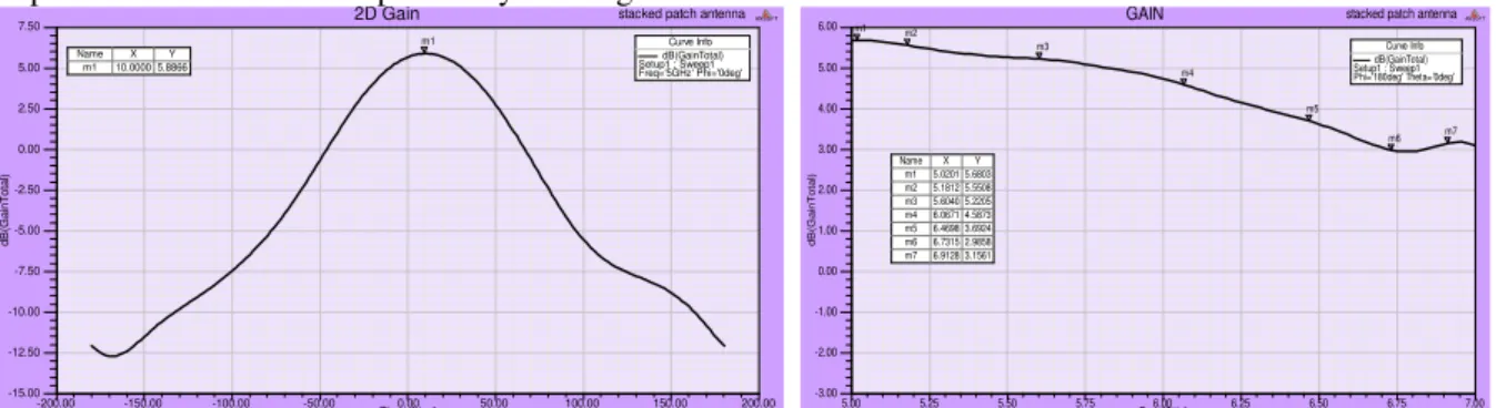
m1 10.0000 5.8866
5.00 5.25 5.50 5.75 6.00 6.25 6.50 6.75 7.00
Freq [GHz] -3.00
-2.00 -1.00 0.00 1.00 2.00 3.00 4.00 5.00 6.00
d
B(G
a
in
T
o
ta
l)
stacked patch antenna
GAIN ANSOFT
m1 m2
m3
m4
m5
m6 m7
Curve Info dB(GainTotal) Setup1 : Sweep1 Phi='180deg' Theta='0deg'
Name X Y
m1 5.0201 5.6803
m2 5.1812 5.5508
m3 5.6040 5.2205
m4 6.0671 4.5873
m5 6.4698 3.6924
m6 6.7315 2.9858
m7 6.9128 3.1561
Fig 5 2D gain curve and Frequency Vs Gain Curve
Antenna radiation pattern is the display of the radiation properties of the antenna as a function
of spherical coordinates (, ). In most cases the
radiation pattern is determined in the far field region for constant radial distance and frequency. For a
linearly polarized antenna, the E and H planes are defined as the planes containing the direction of maximum radiation and the electric and magnetic field vectors respectively. Figure 6 shows the radiation pattern of the antenna in E and H plane.
Fig 6 Radiation Pattern in E and H Fields
Observe that the antenna with a single patch can also generate a circularly polarized radiation
pattern. In this case, the patch should be oriented at the angle of 45 relative to the feed slot.
-200.00 -150.00 -100.00 -50.00 0.00 50.00 100.00 150.00 200.00
Theta [deg] 0.00
10.00 20.00 30.00 40.00 50.00 60.00
d
B(A
xi
a
lR
a
tio
Va
lu
e
)
stacked patch antenna
Axial Ratio ANSOFT
Curve Info dB(AxialRatioValue) Setup2 : LastAdaptive Freq='6.1879GHz' Phi='0deg'
dB(AxialRatioValue) Setup2 : LastAdaptive Freq='6.1879GHz' Phi='90deg'
D. Ujwala et al Int. Journal of Engineering Research and Applications www.ijera.com
ISSN : 2248-9622, Vol. 4, Issue 3( Version 1), March 2014, pp.102-105
www.ijera.com 105 |P a g e
Fig 8 Current Distribution of antenna at 6.1 GHz
IV.
Conclusion
Circularly polarised microstrip stacked patch antenna with rotated patches is presented in this
work. The current design is operating with good
performance characteristics and stable gain
throughout the desired frequency band. All the antenna parameters are simulated using HFSS and their analytical presentation is given in this paper. Axial ratio less than 3dB and VSWR less than 2 are the reasonable things for applicability of this antenna in the real time environment.
V.
Acknowledgments
References
[1] M. C. Pan and K. L.Wong, ―Broadband
circularly polarized microstrip antenna with
a dual-perpendicular feed,‖ Microw. Opt.
Technol. Lett., vol. 24, no. 6, pp. 420–422,
Mar. 2000.
[2] J. Y. Sze, C. I. G. Hsu, Z. Chen, and C. C.
Chang, ―Broadband CPW-Fed circularly
polarized square slot antenna with
lightening-shaped feed line and inverted-L
grounded strips,‖ IEEE Trans. Antennas
Propag., vol. 58, no. 3, pp. 973–977, Mar.
2010.
[3] S. L. S. Yang, A. A. Kishk, and K. F. Lee,
―Wideband circularly polarized antenna with L-shaped slot,‖ IEEE Trans. Antennas
Propag., vol. 56, no. 6, pp. 1780–1783, Jun.
2008.
[4] B.T.P. Madhav, D. Ujwala, Habibulla Khan,
Atluri Lakshmi Tejaswani, Sriram
Guntupalli and Atluri Bala, ―Substrate
Permittivity Effects on the Performance of
Slotted Aperture Stacked Patch Antenna‖,
International Journal of Applied Engineering Research, ISSN 0973-4562, Volume 8, Number 8 (Aug-2013), pp. 909-916.
[5] K. Sarat Kumar, B.T.P.Madhav, T. S. R.
Prasad, G. Sai Rajesh, V. Ratna Bhargavi, J.
V. Suresh, ― Characterization of Substrate Material Effects on Circularly Polarized Triangular Microstrip Antenna with Spur
Lines‖, International Journal of Advances in
Engineering, Science and Technology
(IJAEST), ISSN : 2249-913X , Vol. 2, No. 2, May-July 2012 , pp 326-330.
[6] B. Jyothi, B.T.P.Madhav, V.V.S. Murthy, P.
Syam Sundar, VGKM Pisipati,
―Comparative Analysis of Microstrip
Coaxial Fed, Inset Fed and Edge Fed
Antenna Operating at Fixed Frequency‖,
International Journal of Scientific and Research Publications, ISSN 2250-3153, Volume 2, Issue 2, pp 1-6, February 2012.
[7] B.T.P.Madhav, VGKM Pisipati, R. Sneha,
S. Siva Kumar, V. Priyanka, ― Simulational
Investigation on performance
characterization of Different Microstrip
Coaxial Fed Bowtie Antennas‖,
International Journal of Emerging
Technology and Advanced Engineering, www.ijetae.com, ISSN 2250-2459, Volume 1, Issue 2, December 2011.
[8] T. Nakamura and T. Fukusako, ―Broadband
design of circularly polarized microstrip patch antenna using artificial ground
structure with rectangular unit cells,‖ IEEE Trans. Antennas Propag., vol. 59, no. 6, pp.
2103–2110, Jun. 2011.
[9] Nasimuddin, K. P. Esselle, and A. K.
Verma, ―Wideband circularly polarized stacked microstrip antennas,‖ IEEE Antennas Wireless Propag. Lett., vol. 6, pp.
21–24, 2007.
[10] S. Gao, Y. Qin, and A. Sambei, ―Low-cost
broadband circularly polarized printed
antennas and array,‖ IEEE Antennas Propag.