www.geosci-instrum-method-data-syst.net/2/329/2013/ doi:10.5194/gi-2-329-2013
© Author(s) 2013. CC Attribution 3.0 License.
Instrumentation
Methods and
Data Systems
Drilling cores on the sea floor with the remote-controlled sea floor
drilling rig MeBo
T. Freudenthal and G. Wefer
MARUM Center for Marine Environmental Sciences, University of Bremen, Bremen, Germany
Correspondence to:T. Freudenthal ([email protected])
Received: 11 June 2013 – Published in Geosci. Instrum. Method. Data Syst. Discuss.: 1 July 2013 Revised: 9 December 2013 – Accepted: 9 December 2013 – Published: 20 December 2013
Abstract. The sea floor drill rig MeBo (acronym for
Meeresboden-Bohrgerät, German for sea floor drill rig) is a robotic drill rig that is deployed on the sea floor and oper-ated remotely from the research vessel to drill up to 80 m into the sea floor. It was developed at the MARUM Re-search Center for Marine Environmental Sciences at Bremen University. The complete system – comprising the drill rig, winch, control station, and the launch and recovery system – is transported in six containers and can be deployed world-wide from German and international research ships. It was the first remote-controlled deep sea drill rig to use a wireline coring technique. Compared to drilling vessels this technol-ogy has the advantage of operating from a stable platform at the sea bed, which allows for optimal control over the drilling process. Especially for shallow drillings in the range of tens to hundreds of metres, sea bed drill rigs are time-efficient since no drill string has to be assembled from the ship to the sea floor before the first core can be taken. The MeBo has been successfully operated, retrieving high-quality cores at the sea bed for a variety of research fields, including slope stability studies and palaeoclimate reconstructions. Based on experience with the MeBo, a rig is now being built that will be able to drill to a depth of 200 m.
1 Introduction
Conventional methods of sampling the sea floor from re-search ships include the use of vibracores, gravity cores and piston cores. With these robust and reliable instruments, cores with lengths of 5–15 m (up to 50 m in rare cases) can be retrieved in areas of unconsolidated sediments on the sea
floor (Hebbeln, 2003). Dredging is used to collect blocks of hard rock lying on the sea floor.
Drilling ships are usually employed when longer sediment cores are necessary or if cores from hard-rock provinces are targeted (Hebbeln, 2003). These ships can drill cores down to several hundred metres, or even kilometres deep. How-ever, the use of drilling ships is expensive and not efficient for shallow drilling needs (McGinnis, 2009). Before the ac-tual drilling process can begin, a drill string has to be assem-bled that extends from the ship to the sea floor. Vibrations in the drill string and movements of the ship prevent opti-mal control of the drill-head pressure, which considerably compromises the core quality, especially in the upper tens of metres.
Fig. 1.Typical operational setup for a remote-controlled drill rig that is lowered to the sea floor. As an example, the sea floor drill rig MeBo and the research vesselMaria S. Merianis shown.
2 Examples and advantages of robotic drilling systems
Robotic drilling rigs that are lowered onto the sea floor from multi-purpose research vessels and that retrieve cores from the sub-bottom by remote control from the ship (Fig. 1) can help to fill the gap between relatively inexpensive conven-tional methods – like vibracoring, gravity coring or piston coring – and the use of drill ships. For deployment on the sea floor, several drill rigs have been developed that use a single core barrel and can drill to a depth of up to 5 m, as well as other rigs that have a drill-pipe magazine (multi-barrel). For the latter, extension pipes can be attached to the drill string and thus significantly greater coring depths can be achieved. To our knowledge, the first example of a remotely oper-ated sea floor drill rig was the MARICOR, developed in 1973 by Atlas Copco. This rig was configured for deployment on continental shelves down to 200 m water depth and a drilling depth of 60 m using a diamond rotary drilling method.
The British Geological Survey (BGS) operates two single-barrel drill rigs (Wilson, 2006). The 5 m rock drill (RD1) was developed in 1982. A smaller 1 m drill can retrieve an oriented core for palaeomagnetic studies (MacLeod et al., 2002). In 2006 the BGS developed a multi-barrel rig that could drill to a depth of 15 m (Wilson, 2006) and has now been upgraded for a drilling depth of 50 m.
In 1989/1990 the American company Williamson and As-sociates built a 3 m drill rig (Johnson, 1991), and in 1996, 2005 and 2008 they produced the Benthic Multicoring Sys-tems BMS-1, BMS-2 and BMS 3, respectively. The BMS drills are operated on the research ship Hakurei No. 2 by the Metal Mining Agency of Japan and can drill to a depth of 20 m (Ishibashi et al., 2007) in unconsolidated sediments or in hard rocks. In 2008 Williamson and Associates devel-oped a sea bed drill rig called an Autonomous Coring System
with energy from the ship through a special steel-armoured cable. These drilling tools present new possibilities for sam-pling from conventional research ships. The multi-barrel rigs are especially well suited for filling the growing need by both marine research and offshore industry for cores of 30–100 m length on the continental shelf areas as well as in the deep sea. These remote-controlled drills have significant advan-tages over drill ships.
– Ship and drill-string motion due to wind, currents and waves do not affect the quality of the drilling process because the work is done from a stable platform on the sea floor.
– Robotic drill rigs can be launched from various avail-able multi-purpose research ships. This can reduce the mobilization costs for worldwide deployment. – As a rule, drilling ships are expensive and heavily
booked. By avoiding the time-consuming assembly of a drill string from the drilling ship to the sea floor, the use of drill rigs placed on the sea floor can be substan-tially more time- and cost-effective.
A similar concept to the remote-controlled drilling on the sea floor is implemented by drills mounted on submarine robots (remotely operated vehicle, ROV). The ROV is connected to the vessel by an umbilical and is used for navigation, data transfer, and supply of hydraulic energy for the drill rig. The MBARI ROV-mounted rig can drill horizontal cores with a maximum length of 1 m (Stakes et al., 1997). The Rovdrill®, which was developed by Perry Slingsby, drills vertically and can attain depths of up to 20 m. The third generation of this development, called Rovdrill 3, is designed for a maximum coring depth of more than 80 m (Spencer et al., 2011).
3 The sea floor drill rig MeBo
Fig. 2.The sea floor drill rig MeBo during the deployment start from the research vessel RVPourquoi Pas?in November 2011 (photo: T. Klein, Marum).
2007). MeBo is the acronym for Meeresboden-Bohrgerät, German for sea floor drill rig. This is the first drill rig de-veloped and operated by a scientific institute that can drill cores up to 80 m deep in unconsolidated sediments and in hard rocks. It is the first robotic deep sea drilling rig in the world that can drill cores using both conventional and the advanced wireline methods.
As far as is possible, the MeBo uses proven technology that has been time-tested in onshore drilling systems or on commercial ROVs. Special requirements for its construction included the following:
– convenience of transportation on land and sea, – 10 t maximum weight,
– drilling capability in both unconsolidated sediments and hard rocks,
– drilling depth of at least 50 m, – core diameter of 50–80 mm,
– deployment depth up to 2000 m (with the option to 4000 m)
It was developed in close cooperation with the companies Prakla Bohrtechnik GmbH and Schilling Robotics. The Ger-man company Prakla Bohrtechnik GmbH in Peine was pri-marily responsible for the mechanical and hydraulic devel-opment. The California-based company Schilling Robotics developed the core-barrel magazine with the loading arm and also provided the telemetry system for data transfer and operating energy. MARUM was responsible for the system design, energy supply and deployment concept and also de-veloped the control system (hardware and software) for the MeBo.
Fig. 3.View toward the stern on the working deck of the research
vesselMeteorduring deployment of the MeBo. At the front of the picture are the workshop and control containers, behind them the drill-pipe storage and winch, and behind those the launch and re-covery system for the MeBo (photo: V. Diekamp, Marum).
The system comprises the drill rig, the winch with 2500 m of armoured special cable (umbilical), a launch and recovery system (MeBo-LARS), the control unit, a workshop with re-placement parts, and storage for the drill pipe (Fig. 1). The control unit, workshop and drill-pipe storage are each accom-modated in a 20 ft (6.058 m) shipping container. The winch is in a transport frame the same size as a 20 ft shipping con-tainer. The drill rig and the MeBo-LARS are each stowed in a 20 ft open-top shipping container, with the LARS having to be disassembled for storage and transport. The containerized transport concept allows for quick and efficient worldwide transportation of the system as well as the rapid assembly and breakdown on the research vessel being used (Fig. 3).
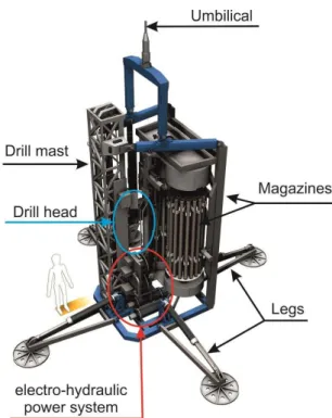
Fig. 4.Schematic overview of the major components of the MeBo (drawing: dibi Multimedia).
The MeBo is hydraulically powered. Four hydraulic pumps powered by two electric motors provide a working pressure of up to 207 bar greater than the ambient pressure. The motors run at a voltage of 3000 V and have a power of 65 kW each. We use the high voltage in order to minimize the loss of power during transmission within the 2500 m-long umbilical. Several underwater cameras and sensors are used to monitor the drilling process.
The central element of the MeBo is the feed system with the drill head (Fig. 4). It includes the mast as a guide for the carriage, which is cable-driven by the hydraulic feed cylin-der. The feed system supplies the necessary thrust for drilling and pushing the drill string into the hole, as well as for disas-sembling the drill string later. The drill head provides rotation and the necessary torque for screwing the drill pipe together and for the rotary drilling. It has a hollow spindle to allow the flushing water into the drill string with the help of the flush-ing water pump. We flush with sea water to cool the drill bit and to wash the loose drill cuttings out of the hole.
The necessary core barrels and drill pipe are stored in two rotating magazines. Depending on the geology of the sub-surface, these magazines can be loaded with different kinds of core barrels. A loading arm is used to grab the required pipe as well as for putting it back into the magazines for stor-age. This is used in combination with a stationary foot clamp to hold the drill string, and a rotating clamp on the drill head to assemble and break down the drill string. In conventional
drilling techniques a second stationary clamp is necessary for casing pipe, which is needed to stabilize the hole.
4 Wireline drilling technique
To our knowledge, MeBo is the first remote-controlled deep sea drill rig that uses the wireline drilling technique. With this method, after penetration of one core length (2.35 m is used for the MeBo) the core barrel holding the cored sam-ple is pulled up through the drill string. For this, a steel cable with an “overshot” (grabbing device) is dropped into the drill string after the drill head is released from the string (Fig. 5). When the core barrel is pulled out of the drill string the over-shot is released and the core barrel with the core sample is placed into the magazine. The loading arm takes a new empty core barrel from the magazine and inserts it into the drill string. The inner core barrel is dropped through the drill string, its fall moderated by the water in the string, and at the bottom it is stopped by a shoulder ring in the drill pipe. After lengthening the drill string by an additional joint of pipe (drill rod) from the magazine, and screwing it into the bottom-hole assembly, the next core can be drilled.
Wireline drilling is often used in drilling systems on land. This method is considerably faster than conventional drilling, which requires breaking down the complete drill string after each penetration of a single core length to retrieve the core (McGinnis, 2009). In wireline drilling there is no need for an additional casing pipe to stabilize the hole because the drill string remains in the hole for the duration of the drilling pro-cess. This is especially important in soft formations to avoid the risk of hole collapse while the core is being retrieved.
View of the lower fixed foot clamp of the MeBo. The “overshot” is lowered into the
Fig. 5.View of the lower fixed foot clamp of the MeBo. The “over-shot” is lowered into the drill string on a steel cable (photo: Marum).
pulled up to the deck of the research vessel immediately af-ter it was drilled. The MARICOR project, however, was can-celled after its first trials (A. Oden, personal communication, 2003). All subsequent remote-controlled drill rigs that were developed up to 2007 for use on the sea floor (BMS, PROD, Rovdrill) use the conventional drilling procedure. Because wireline drilling involves a much higher complexity of oper-ational steps, we at MARUM also initially decided to config-ure the MeBo for conventional coring. After four successful research expeditions with the MeBo through 2007 (Freuden-thal and Wefer, 2007), we undertook the further developmen-tal decision to upgrade the MeBo for use with the wireline technique.
In contrast to land-based drilling systems, remote-controlled operation of wireline drilling cannot be manually supported. During the upgrade of the MeBo for use with wireline drilling, special attention was therefore given to the processes that are normally supported by the drill foreman on the rig. These include guiding the overshot into the drill string with an additional manipulator, checking the landing of the inner core barrel on the shoulder ring, secure wind-ing of the winch for the cable, releaswind-ing the overshot from the core barrel after retrieval from the drill string (Freuden-thal et al., 2012) and preparation of the overshot for the next application.
Due to the space saved in magazine storage for the addi-tional pipe needed for convenaddi-tional drilling, the maximum drilling depth is increased from 50 m to over 80 m with the wireline method (Table 2). The advantages of the wireline method have been demonstrated on 10 expeditions with the MeBo since 2008. Average core recovery rates were close to 80 % in different types of geologies including hemipelagic muds, gas-hydrate-bearing sediments, sands, glacial till and carbonate rock. Since wireline coring tools were initially de-veloped for hard rock drilling, we dede-veloped special
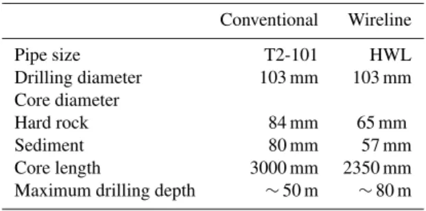
adap-Table 2.Comparison of drill-pipe sizes used by the MeBo for
con-ventional and wireline drilling.
Conventional Wireline
Pipe size T2-101 HWL Drilling diameter 103 mm 103 mm Core diameter
Hard rock 84 mm 65 mm Sediment 80 mm 57 mm Core length 3000 mm 2350 mm Maximum drilling depth ∼50 m ∼80 m
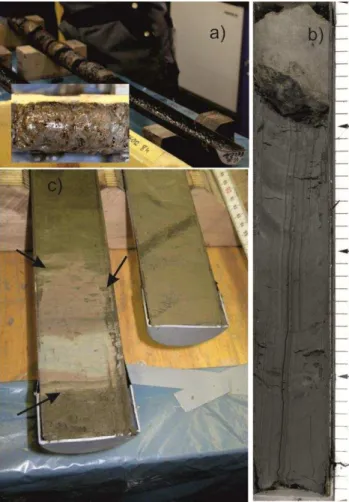
tions for improving the core recovery for soft sediments. Ex-amples of cores collected in different types of sediments are shown in Fig. 6.
5 Auxiliary equipment
An autonomous probe for obtaining bore-hole measurements has also been developed for use with the MeBo. In a proce-dure called logging while tripping, the probe, equipped with its own energy source and data storage, is lowered into the drill string after the last core barrel has been retrieved. After the probe has landed on the shoulder ring at the bottom of the hole, the drill string is pulled out and disassembled. The probe, while being raised with the drill string, continuously measures the geophysical properties of the borehole and the in situ sediments and rocks. Major advantages of the logging-while-tripping method are a minimum time requirement for the borehole logging since the drill string has to be tripped out anyway as well as the capability of logging unstable for-mations since the drill string stabilizes the drilled hole during the logging.
Figure 7 shows the results of core drilling and borehole logging at station GeoB 16602 drilled during the RVSonne
Fig. 6.High-quality cores drilled with the MeBo from massive gas hydrate layers(a), and hemipelagic muds containing authigenic car-bonate precipitates(b) and ash layers(c). Arrows point to sharp contact at the base of the ash layer and bioturbation structures at the top, which are indicators of minimum disturbance of the sediments during drilling. (photos: Marum).
gamma ray signal is expressed in the internationally accepted gAPI unit (Ellis and Singer, 2007). A close correlation of the logging profiles is observed between the independently ac-quired profiles at this site. Natural gamma ray signal (NGR) ranges from 44 to 90 gAPI. The variations in NGR are mainly attributed to changes in concentrations of potassium (0.5– 1.6 %) and thorium (4.1–13.0 ppm), whereas uranium con-centrations are fairly low (1.2–3.1 ppm).
Clays are the main host minerals for thorium and potas-sium in marine sediments. The variability in NGR can there-fore be interpreted as an indicator of changes in terrestrial sediment input into the South China Sea at the two sites. Since the monsoon system is a key factor controlling weath-ering and terrigenous material transport by rivers, the bore-hole logging results will help in reconstructing past climate changes in that area.
Fig. 7. Core recovery with a gravity core (GeoB16602-4) and
three separate MeBo deployments (GeoB16602-5, GeoB16602-7, GeoB16602-8) and borehole logging results of MeBo deployments GeoB16602-5 and GeoB16602-7 at the continental slope of the South China Sea at 950 m water depth.
Borehole instrumentation and the hydraulic sealing of the borehole against the overlying ocean body with a CORK (circulation obviation retrofit kit) is required for long-term monitoring of borehole pressure changes related, for ex-ample, to earthquakes and fluid migration within the sedi-ments (Becker and Davies, 2005; Kopf et al., 2011). An au-tonomous MeBo-CORK instrument was developed that can be deployed with the MeBo after core drilling is completed (Kopf et al., 2013). It was installed in a custom-built MeBo drill string termination and deployed for the first time in June 2012 during an expedition of the research vesselSonne
(Fig. 8). It contained pressure and temperature transducers in the borehole as well as outside the borehole for sea floor ref-erence. This instrument also includes a data logger, a battery unit and an acoustic modem for data transfer. Unlike other CORK systems the MeBo approach does not require instal-lation assistance by ROVs (Becker and Davies, 2005) and is therefore versatile to install.
6 MeBo operations
Table 3.Vessels used so far for the operation of the MeBo.
Research Length Gross A-Frame SWL Expeditions
Vessel [m] tonnage [kN] [Name (year), chief scientist, area]
Celtic Explorer 65.5 2425 250 CE0511 (2005), Freudenthal, Baltic Sea CE0619 (2006), Murray, off Ireland CE0810 (2008), Wheeler, off Ireland Maria S. Merian 94.8 5573 200 MSM04/4 (2007), Freudenthal, off Morocco
MSM15/3 (2010), Huhn, off Sicily MSM30 (2013), Hanebuth, W. Barents Sea Meteor 97.5 4280 200 M65/3 (2005), Wefer, off Morocco
M76/1 (2008), Zabel, off Namibia M78/3 (2009), Wefer, off Argentine M84/2 (2011), Bohrmann, Black Sea Sonne 97.6 3557 100 SO211 (2010), Hebbeln, off Chile
SO221 (2012), Mohtadi, South China Sea SO222 (2012), Kopf, off Japan
Pourquoi Pas? 107.6 7854 220 GUINECOMeBo (2011), Sultan, off Nigeria
Fig. 8.Picture of a MeBo-CORK installed in June 2012 with the
MeBo. The picture was taken a few days after installation with a towed camera sled, the Ocean Floor Observation System (OFOS) of the research vesselSonne. Note the imprint of the base frame and of the legs of the MeBo on the sea floor. The distance weight on a 2 m rope in the lower right of the picture belongs to the camera sled and assists the winch driver in assessing distance to sea floor (photo: Marum).
A length of free deck space of approximately 16–20 m is required in front of the A-frame for installation of the launch and recovery system of the MeBo and the 30 t lift umbilical winch. Additional deck space is needed for storing the work-shop container, the drill tool container and the control con-tainer. The workshop container hosts spare parts and tools for maintenance and repair of the system. Core barrels and rods, as well as drill bits and core catchers, for different types of geology are stored in the drill tool container. The opera-tor console includes a video wall for displaying the images
of eight sub-sea cameras mounted on the drill rig as well as three deck cameras and belongs to the fixed installations within the control container. Together with the launch and re-covery system, the winch, the drill rig and the containers, the payload of the MeBo system sums up to approximately 90 t. The MeBo is operated by a total of ten technicians. Three shifts of two operators each alternate in running the drill rig 24 h per day. Four technicians assist the launch and recov-ery, prepare the drill tools, change the loading of the mag-azines and conduct the maintenance and repair (if required) when the MeBo is on deck. The turnover time between two deployments typically takes 12 h, while a drilling operation down to 80 m below sea floor in soft sediments requires 30 to 36 h operation time.
Approximately 2000 m of drilling has been done so far during 101 deployments (conventional and wireline drilling) at water depths between 10 and 2050 m. The average core recovery was 73 % in different types of geologies includ-ing sedimentary and crystalline rocks, glacial tills, sands and hemiplegic muds. Recovery rates of more than 90 % were achieved especially in hard rock formations and cohesive sediments, while sands and gravels are difficult to sample with the wireline rotary drilling method.
Based on the experience of the successful MeBo develop-ment and deploydevelop-ments, we are presently developing, with funding from the Federal Government of Germany (Min-istery of Education and Research, BMBF), the second-generation MeBo: MeBo200. This drill rig will be able to conduct core drilling down to 200 m below sea floor. Its de-velopment is within a cooperation of the company BAUER Maschinen GmbH – responsible for the drill mechanics and hydraulics – and MARUM. By optimizing the interplay be-tween loading arm, chucks and the feeding system, we were able to increase the stroke length from 2.35 to 3.5 m. The MeBo200 is mounted in a 20 ft transport frame, allowing for standard container shipping. As a result of this it was pos-sible also to increase the loading capacity of the magazines, which together with the increased stroke length results in a substantial increase of the drilling depth capabilities.
8 Summary and conclusions
The sea floor drill rig MeBo is a robotic drill rig that is de-ployed on the sea bed and remotely controlled from the re-search vessel. H-size drill tools for wireline core drilling are stored in two magazines on the drill rig and allow for drilling down to 80 m below sea floor for coring soft sediments as well as hard rocks. A 2500 m-long umbilical is used for lift-ing the 10 t device as well as for energy supply and data transfer. The MeBo system comprises the drill rig, the lift umbilical winch, the control station and the launch and re-covery system, and is transported in six containers. It is de-ployed worldwide from German and international research ships and proved its capability during 14 scientific expedi-tions between 2005 and 2012. Average core recovery rates of 73 % were achieved in different types of geologies in-cluding hemipelagic muds, gas-hydrate-bearing sediments, sands, glacial till and carbonate rock. Besides core drilling, the MeBo is used for borehole logging in the logging-while-tripping mode as well as for the instrumentation of bore-holes for long-term monitoring of pressure and temperature changes within the sediments. Experience with the MeBo is now being used for developing a second-generation drill rig
Pourquoi Pas? and Celtic Explorer for their support during the research expeditions with the MeBo.
Edited by: A.-M. Harri
References
Ai, F., Kuhlmann, J., Huhn, K., Strasser, M., and Kopf, A.: Subma-rine slope stability assessment of the central Mediterranean con-tinental margin: the Gela Basin, in: Submarine Mass Movements and Their Consequences, edited by: Krastel, S., Behrmann, J.-H., Völker, D., Stipp, M., Berndt, C., Urgeles, R., Chaytor, J., Huhn, K., Strasser, M., and Harbitz, C. B., Springer, 225–238, 2013. Becker, K. and Davis, E. E.: A review of CORK designs and
op-erations during the Ocean Drilling Program, Proc. IODP, 301, doi:10.2204/iodp.proc.301.104.2005, 2005.
Ellis, D. V. and Singer, J. M.: Well logging for earth scientists, 2nd Edn., Springer, Dordrecht, 692 pp., 2007.
Freudenthal, T. and Wefer, G.: Scientific drilling with the sea floor drill rig MeBo, Ocean Drilling, 5, 63–66, 2007.
Freudenthal, T., Mühlenbrock, S., and Cwiekala, T.: Hakenfänger, Patent No. DE102008002835 B4 2012.09.06, 2012.
Hebbeln, D.: State of the art and future prospects of scientific cor-ing and drillcor-ing of marine sediments, in: Ocean Margin systems, edited by: Wefer, G., Billet, D., Hebbeln, D., Jørgensen, B. B., and van Weering, T. C. E., Springer, 57–66, 2003.
Ishibashi, J.-I., Marumo, K., Maruyama, A., and Urabe, T: Direct access to the sub-vent biosphere by shallow drilling, Oceanogra-phy, 20, 24–25, 2007.
Johnson, H. P.: Next generation of sea floor samplers, EOS, 82, 65– 66, 1991.
Kopf, A., Hammerschmidt, S., Saffer, D. M., Lauer, R., Davis, E. E., LaBonte, A., Meldrum, R., Heesemann, M., Macdonald, R., Toczko, S., Wheat, C. G., Jannasch, H., Edwards, K., Haddad, A., Orcutt, B., Villinger, H., Araki, E., Kitada, K., Kimura, T., and Kido, Y.: The SmartPlug and GeniusPlug: Simple retrievable ob-servatory systems for NanTroSEIZE borehole monitoring, Proc. IODP, 332, doi:10.2204/iodp.proc.332.105.2011, 2011
Reuter, C., Reuter, M., Rosiak, U. D., Schmidt, W., Seiter, C., Spiesecke, U., Stachowski, A., Steiner, A., Takanori, O., Tryon, M., Vahlenkamp, M., Wei, J., Wintersteller, P., and Zarrouk, M. K.: Report and preliminary results of RV Sonne CRUISE SO222: MEMO – MeBo drilling and in situ Long-term Monitoring in the Nankai Trough accretionary complex, Japan, Berichte aus dem Fachbereich Geowissenschaften der Univ. Bremen, 297, 121 pp., 2013.
Krastel, S., Wefer, G., Hanebuth, T. J. J., Antobreh, A. A., Freuden-thal, T., Preu, B., Schwenk, T., Strasser, M., Violante, R., Winkel-mann, D., and M78/3 Shipboard Scientific Party: Sediment Dy-namics and Geohazards off Uruguay and the de la Plata River region (Northern-Argentina, Uruguay), Geo-Mar. Lett., 31, 271– 283, 2011.
MacLeod, C. J., Escartín, J., Banerji, D., Banks, G. J., Gleeson, M., Irving, D. H. B., Lilly, R. M., McCaig, A. M., Niu, Y., Allerton, S., and Smith, D. K.: Direct geological evidence for oceanic de-tachment faulting: The Mid-Atlantic Ridge, 15◦45′N, Geology, 30, 879–882, 2002.
Martínez-Méndez, G., Hebbeln, D., Mohtadi, M., Lamy, F., De Pol-Holz, R., Reyes-Macaya, D., and Freudenthal, T.: Changes in the advection of Antarctic Intermediate Water to the northern Chilean coast during the last 970 kyr, Paleoceanography, 28, 1– 12, doi:10.1002/palo.20047, 2013.
McGinnis, T.: Seafloor Drilling, in: Drilling in extreme environ-ments, edited by: Bar-Cohen, Y. and Zacny, K., Wiley, 309–345, 2009.
Pallanich, J.: Prod probes Statoil’s seabed soils, Offsh. Engin., February 2010, 42–44, 2010.
Sager, W., Dick, H., Fryer, P., and Johnson, H. P.: Requirements for robotic underwater drills in U.S. marine geological research. Report from a workshop, 3–4 November 2000, http://usssp-iodp. org/workshop/robotic-underwater-drills/ (last access: 19 Decem-ber 2013), 2003.
Spencer, A., Remmes, B., and Rowson, I.: A fully integrated solu-tion for the geotechnical drilling and sampling of seafloor mas-sive sulfide deposits, Proceedings Offshore Technology Confer-ence OTC 21439, 2011.
Stakes, D. S., Holloway, G. L., Tucker, P., Dawe, T. C., Burton, R., McFarlane, J. A. R., and Etchemendy, S.: Diamond rotary coring from an ROV or submersible for hardrock sample recovery and instrument deployment: The MBARI multiple-barrel rock coring system, Mar. Technol. Soc. J., 31, 11–20, 1997.
Stuart, S.: The remote robot alternative, International Ocean Sys-tems , 8, 23–25, 2004.
Wilson, M.: Drilling at sea, Earthwise, 23, 32–33, 2006.