62
SIMULATION STUDY OF CUTTING TOOL SYSTEM USING INTELLIGENT ACTIVE FORCE CONTROL
M.M. Hatifi1, M.F. Hassan1 and A.R.Yusoff2
1
Noise and Vibration Control Research Group
Faculty of Mechanical Engineering, Universiti Malaysia Pahang, 26600 UMP, Pekan, Pahang, Malaysia;
Phone: +6013-9867376, Fax: +609-4242202 Email: hatifi@ump.edu.my
2
Faculty of Manufacturing Engineering, Universiti Malaysia Pahang, 26600 UMP, Pekan, Pahang, Malaysia
ABSTRACT
This paper presents a study of vibration control through an active force control (AFC) scheme. AFCs are used widely in dynamic system control and are highly robust control schemes, although under unknown disturbances and operation conditions. In this study, the AFC was incorporated with a conventional proportional-integral-derivative (PID) controller to control an active vibration isolation system. A cutting tool of a turning machine with two degrees of freedom is used in this study. A harmonic force due to an unbalanced rotating mass and a sinusoidal response that represented an internal disturbance were applied to both axes (X and Y) of the models, respectively. Generally, the estimated mass (EM) is the most significant parameter in an AFC scheme; thus, the interest in this study was to obtain the EM via a conventional crude approximation method and an intelligent fuzzy logic method. A new AFC scheme with fuzzy logic control (FLC) was proposed (AFCFLC), which is an AFC combined with a PID and FLC. The main purpose of this scheme was to obtain the optimum EM value via the intelligent method and to suppress vibration. Finally, a demonstration of a comparison study between each control scheme was carried out, which revealed clearly that the proposed AFCFLC scheme was the most superior control method for vibration isolation in both axes of the cutting tool models.
Keywords: Simulation; active force control; fuzzy logic; chatter.
INTRODUCTION
63
transmitted, or action taken at the receiver to reduce its response to unwanted vibration (Harris & Piersol, 2002)
Instead of controlling vibration at the source and receiver, modification of the transmission path has a significant role in vibration control (Ogata, 2002). Vibration along the transmission path is magnified by resonance and reduced by damping. In vibration control, it is crucial to avoid resonance and to incorporate as much damping as possible. A vibration absorber and a vibration isolator are two important devices for reducing vibration along a transmission path. A vibration absorber is a secondary mass spring system that is tuned to absorb energy from the primary system to which it is attached. The secondary mass is usually small in comparison with the primary mass. The motion of the secondary mass is in opposite phase to that of the primary mass and therefore, it imparts a reaction that opposes the motion of the primary system. Petterson, Hancasson, Cansson & Olsson (2001) found and used active vibration control as a mechanism for reducing vibration on a machine and cutting tools. Following their study, many other researchers made improvements and introduced new control systems.
Currently, the intelligent active force control (IAFC) scheme has become another popular control scheme, which is used widely in robot control (Mailah & Rahman, 2000). Generally, the IAFC scheme is a combination of an IAFC loop and a conventional proportional-integral-derivative (PID) controller in one control scheme. The most important parameters in this scheme are the assumption of the estimated mass in the IAFC loop and the tuning of the PID gain in the PID controller. The application of an intelligent method in an IAFC scheme for a robot arm control has been presented by Mailah and Rahman (1999). These methods have also been applied in suspension systems (Mohamad, 2004). Priyandoko, Mailah and Jamaluddin (2009) used adaptive neuro AFC on a vehicle suspension system. All researchers used intelligent methods, such as iterative learning and fuzzy logic control (FLC) to obtain the estimated mass.
In a lathe machine, the cutting tool is usually flexible and slim. If the workpiece is hard, then significant chatter may occur during the machining process. To suppress the chatter or vibration, AFC is essential. In order to control the chatter effectively, in this paper, we show a simulation and comparative study of a cutting tool by using several controls, such as PID, AFC, and artificial intelligence in cooperation with AFC.
DYNAMIC MODEL LATHE CUTTING TOOL
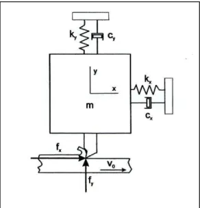
For lathe or turning machines, the position of the cutting tool is static and the workpiece is moved to produce shape of the product. For this study, we use a passive two degrees of freedom (TDOF) cutting tool system, as shown in Figure 1. There will be vibration of the cutting tool in the x and y directions, but movement in one direction (V0) only for
the workpiece.
The dynamic analysis for a passive TDOF cutting tool system will be done separately for both axes. By using Newton’s second law ∑ , the mathematical modeling can be shown as in Eq. (1.
(1)
where is force and is the initial velocity acting in the direction of the x-axis. is the spring force and is the damping force, which can simplified as shown below.
64
= (3) = (4)
All the above can be substituted in Eq. (1) to produce Eq. (5).
(5)
Figure 1. Two degrees of freedom cutting tool model.
The unit of initial velocity is m s-2 and therefore, to balance the equation into the same units, we use Eq. (6).
(6)
[ ] (7)
| | (8)
Substitute Eqs. (7) and (8) into Eq. (6) and we obtain Eq. (9).
[ | |] [ | |] (9)
Then, Eq. (9) can be substituted in Eq. (5) to produce Eq. (10).
[ | |] [ | |]
(10)
65
(11)
where is the force that acts in direction of the y-axis. is the spring force and is the damping force, which can be simplified as shown below.
= (12)
= (13) = (14)
Then, we substitute all the equations above into Eq. (10) and obtain Eq. (15):
(15)
The piezo actuator stiffness is an important parameter for calculating the force generation, resonant frequency, full-system behavior, etc., compared with its mass and damping parameter. By taking account of piezo actuator stiffness only, it becomes linear and it can be represented as follows:
Fa kTx (16)
A piezo actuator and sensor embedded in the cutting tool holder, which is controlled by the active controller system, transforms the system to an active system and the equation becomes:
(17)
(18)
To complete the mathematical analysis for the dynamic model of the cutting tool, the derived parameters of the equations need to be substituted. The mathematical model consists of two axes with nine parameters that need consideration. All parameters were obtained from a previous study on a lathe machining process. There are disturbances that will be introduced into the system, such as vibration forces that occur from the machine body during the machining process. These forces can be classified as internal or external disturbance forces. In the active system model (cutting tool), a harmonic force due to the internal vibration or external vibration is applied, which represents a force disturbance. This force vibration can be collected by using modal testing.
PROPORTIONAL-INTEGRAL-DERIVATIVE (PID) CONTROLLER
A PID controller is the most widely used control method. It is a simple and effective feedback control. It also provides fast response and good system stability, especially for slow speed operation or during very small disturbances. However, the performance of PID controller is reduced when the system is operating at high speed and in the presence of larger disturbances. The input signal for the PID controller is the error signal between the reference input and the output response. The output signal from a PID controller is then used to control the actuator in order to change the response of the dynamic system (Nice, 2008). The basic Eq. (19) governing the controller is expressed as follows:
∫ (19)
66
(20)
where and , i.e., is the integral time constant and is the derivative
time constant. Meanwhile, the relation between the integral time constant and derivative time constant can be expressed as , where α is a constant value.
(21)
ACTIVE FORCE CONTROL
AFC was first proposed by Hewit (1998) who applied this strategy to control a dynamic system in the early 1980s. It showed that a system controlled by AFC remains stable and robust, even in the presence of known and unknown disturbances. An intelligent method had been applied to the control scheme to make it robust.
Figure 2. Basic AFC scheme for cutting tool system.
Mailah and Rahman (1999, 2000) applied IAFC to robot arm control with an FLC and neural network. The results indicate that AFC is superior compared with conventional methods in controlling a robot arm. Figure 2 shows a schematic diagram of the IAFC strategy applied to a dynamic system. It presents a block diagram of the AFC with PID applied to the cutting tool system in this study The IAFC scheme serves as a disturbance rejection scheme in which the disturbance force Fd* can be compensated in the feedback loop if the EM is estimated well. Hence, the essence of the AFC strategy is to obtain the estimated disturbance force Fd* via measurements of mass acceleration a, the actuator force Fa*, and an appropriate estimation of the mass EM*, as described in Eq. (22):
(22)
67
methods and FLC or other iterative learning methods have been used to estimate the mass (Rakiman, 2003).
APPLICATION OF FLC IN AFC
A fuzzy system is a knowledge-based or rule-based system. The system’s knowledge base is constructed in the form of fuzzy IF-THEN rules based on human control behavior. The ability of the fuzzy system to provide a systematic procedure to transform the knowledge base into a nonlinear mapping amplifies the engineering application of the fuzzy system (Ross, 2004).
The fuzzy concept was first introduced by Zadeh (1965) in his seminar paper entitled “Fuzzy Set”. Following further research, Zadeh (1973) published another seminar paper entitled “Outline of a new approach to the analysis of complex systems and decision processes”. The concept of linguistic variables and the application of fuzzy IF-THEN rules to formulate human knowledge are proposed in that paper. Consequently, Zadeh had established the foundation for fuzzy control. To improve the AFC scheme, classical and new intelligent methods have been suggested for inclusion in this scheme. A combination of AFC and an iterative learning method, fuzzy logic has been proposed before for different kinds of dynamic systems and it has proved effective in determining the estimated mass of the system. Therefore, for this project, FLC will be applied as the intelligent aspect of the AFC scheme for the estimation of the mass.
The primary step in the fuzzy logic (FL) controller design is the selection of the input and output variables for the FL controller. According to Priyandoko et al. (2009), the reference output of the system and error are suitable as input variables for most FL controllers. Thus, the input variables used in this study are the reference output and the error, which in this study is defined as the error between the step input and the measured mass displacement output.
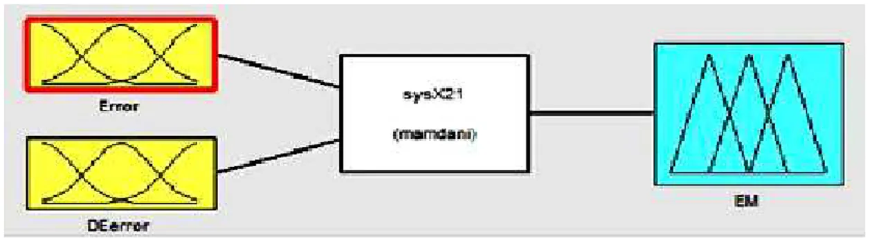
Figure 3. FIS editor for active cutting tool dynamic system for both axes.
68
Figure 4. Triangle-shaped membership function of the output.
The first step of an FL controller is the fuzzification of the controller inputs, based on the membership function design for the input. According to the active cutting tool dynamic system, mass displacement was selected as the input of the FL controller, which was fuzzified by using a triangle-shaped membership function, as shown in Figure 4. The membership function was defined by five linguistic variables: very small, small, medium, large, and very large. Those five rules will be explained in the next paragraph. The range of error input is limited between -0.05 to 0.05. The fuzzification of the controller output was also fuzzified using the triangle-shaped membership function and defined by five linguistic variables: very small, small, medium, large, and very large. The range of the EM is limited between 0.1 and 550 kg. This range had been obtained from the AFCCA stage, which means that the value from the crude approximation method in estimating the EM will be used as the limitation range to obtain a more precise result. The final step in the Mamdani-type FL controller design is the aggregation and defuzzification using the centroid method. Basically, these two steps are executed automatically by MATLAB/Fuzzy Logic Toolbox® in order to produce the crisp EM output value. There are five types of rules that need to be considered for the active cutting tool dynamic system, which are summarized in Table 1.
Table 1. Set of training rules for FLC (25 IF-THEN Rules).
69
consists of the cutting tool dynamic system, the PID controller, the actuator, and the AFC scheme.
SIMULATION OF THE PROPOSED AFCFLC SCHEME
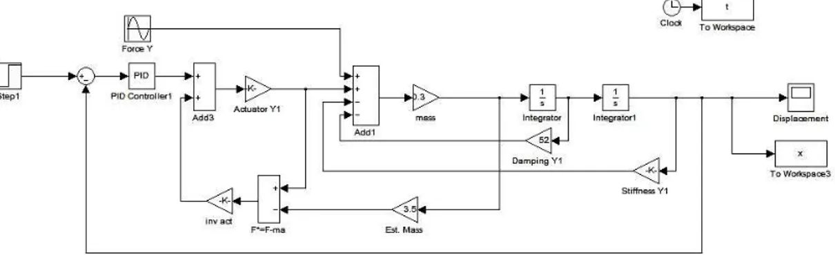
Simulation work was performed using MATLAB/Simulink software. In addition, the Fuzzy Logic Toolbox was also used with MATLAB/Simulink. Before applying FLC, a conventional crude approximation method is applied in the AFC control scheme in order to obtain the best EM. The Simulink diagrams of the AFCCA scheme for ACTD model for both axes are shown in Figure 5.
Figure 5. Simulink diagram of the AFCCA scheme.
Figure 6. Simulink representation of the AFCFLC scheme.
70
Figure 7 shows that the sub-system of FL control has two inputs and one output. Error and derivative of error are the two inputs that have been used to produce EM as an output. Normally, the suitable numerical range for input and output variables used in the FL controller is obtained based on experience. Therefore, the selection of a suitable numerical range is a very important step in this scheme. Other than that, the same PID gain used in the AFCCA scheme is applied in this control scheme.
Figure 7. Sub-system of fuzzy logic Simulink diagram.
SIMULATIONRESULTSANDDISCCUSSION
When the machining occurred, the tuning process of the controller gains was an important task that needed to be done to ensure the control action gave desirable results. The results need to be focused on the suppression of vibration with or without external disturbance. The tuning was done by a heuristic method and an artificial intelligence technique by using step input signals as a reference input signal, because the results obtained are easy to evaluate from a step response graph and to discuss in terms of overshoot, steady state error, rise and settling time, etc. The tuning process for controllers such as the PID can be performed by using heuristic methods for controller proportional, integration, and derivatives. For this experiment, by using another technique such as Ziegler Nichols method to tune PID (Dwyer, 2006), the best values for the controller were KP = 1000, KD = 9, and KI = 89, as shown in Figure 8.
Figure 8. PID tuning for cutting tool model.
0 0.001 0.002 0.003 0.004 0.005 0.006 0.007 0.008 0.009 0.01 0 0.2 0.4 0.6 0.8 1 1.2 1.4 1.6 1.8
2x 10
-3 Time (s) D is p la c m e n t (m )
DISPLACEMENT RESPONSES VS. TIME (X-Axis)
71
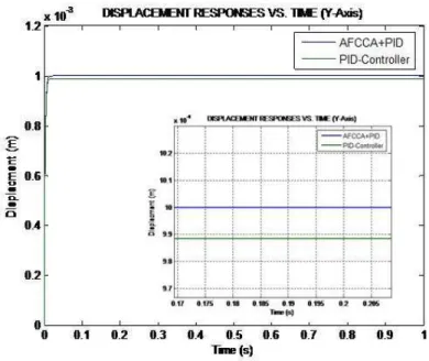
For AFC, a crude approximation technique was used to estimate the appropriate estimated/virtual mass (M*) and it is a constant value. The best EM is found to be 100 kg where overshoot is very small, rise and settling time is fast, and where steady state error is almost zero compared with the other values of M*, as shown in Figure 9. Figure 10 shows the comparative response between the PID and AFCCA schemes. For the AFCCA scheme, the steady state error and the rise and settling time is better than with the PID control scheme. AFCCA gives a smooth response with hardly any vibration. Referring to the close-up view in Figure 10, the PID scheme did not reveal an overshoot compared with AFCCA, but obviously, the vibration or small wave that occurred could not be eliminated.
Figure 9. Plot of mass displacement with different estimated mass (EM).
Figure 10. Plot of mass displacement AFCCA and PID.
0 0.05 0.1 0.15 0.2 0.25 0.3 0.35 0.4 0.45 0.5 -2
0 2 4 6 8 10x 10
-4
Time (s)
E
rr
o
r
(m
)
ERROR (m) VS. TIME (s)
72
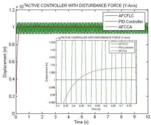
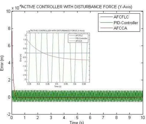
When machining occurs, external disturbances will affect the cutting tool system. These external disturbances introduced into the system affect the AFCCA and PID controller, but only the AFC still gives the same response, as shown in Figure 10. The AFC efficiently and robustly compensates the external disturbance, but not the PID control scheme. External vibration that occurs when the cutting tool of the turning system operates is suppressed effectively by applying the AFC strategy. From the simulation study, the AFCCA gives the best response compared with the conventional PID control scheme, by providing a much more robust performance. The crude approximation method, in computing the EM, is found to be sufficient in producing the desired performance when the external disturbance is constant. During the machining process, several external disturbances are introduced and the crude approximation method is not fully effective because the AFC needs to adapt to the new external disturbance with several range wave signals. To overcome this situation, an artificial intelligence method is introduced into the system as a technique of tuning the EM. The artificial intelligence method, like the FLC, is introduced into the AFC to tune the EM. A comparative study between the PID, AFCCA and the AFCFLC for several disturbance waves is shown in Figures 11 and 12. The PID cannot suppress the vibration unlike AFCCA and AFCFLC. Both AFCs with crude approximation and FLC suppress the vibration or external disturbance successfully, but AFCCA needs to be adjusted if different external disturbances are introduced.
73
Figure 12. Plot of error versus time for step input signals.
CONCLUSION
74
REFERENCES
Altintas, Y. (2000). Manufacturing automation: metal cutting mechanics. Machine Tool Vibration and CNC Design. United Kingdom: Cambridge University Press.
Dwyer, A. O. (2006). Handbook of PI and PID Controller Tuning Rules. London: Imperial College Press.
Harris, C. M., & Piersol, A. G. (2002). Harris’ Shock and Vibration Handbook. 5th Edition. New York: McGraw-Hill.
Hewit J. R. (1998). Advances in Teleoperations. Lecture Note on Control Aspect. CISM.
Mailah, M., & Rahman, N. I. A. (2000). Intelligent Active Force Control of a robot arm using fuzzy logic. Procs. of IEEE International Conference on Intelligent System and Technologies, TENCON 2000, Kuala Lumpur, 2, 291-297.
Mailah, M., & Rahman, N. I. A. (1999). Intelligent AFC of Robot Arm Using Fuzzy Logic. UTM. Jurnal Mekanikal Jilid II.
Mohamad, M. (2004). Vibration Control of Mechanical Suspension System Using AFC. UTM. Master Thesis.
Nice, N. S. (2008).Control System Engineering. 5th Edition. New Jersey. NJ John Wiley & Sons.
Ogata, K. (2002). Modern Control Engineering 4th Edition International. New Jersey. NJ Prentice Hall.Inc.
Petterson, L., Hancasson, L., Cansson, I., & Olsson, S. (2001). Active Control of Machine: Tool Vibration in Cutting Operation in General Lathe. Sweden. Blekinge Institute of Tech.
Priyandoko, G., Mailah, M., & Jamaluddin, H. (2009). Vehicle active suspension system using skyhook adaptive neuro active force control. Mechanical System and Signal Processing, 23(3), 855-868.
Rakiman, K. A. (2003). The application of intelligent AFC of robot manipulator is surface finishing process. UTM, Skudai. Master Thesis.
Ross, T. J. (2004). Fuzzy Logic with Engineering Application. 2nd Edition, New Jersey. NJ John Wiley & Sons.
Zadeh, L. A. (1965). Fuzzy sets. Information and Control, 8(3), 338-353.