System Level Component Modeling of Aircraft
Electrical System Using VHDL-AMS
Xiao Li, Sameer Kher, Shimeng Huang, Vel Ambalavanar and Yang Hu
Abstract—The electric powered aircraft’s secondary system has advantages of cost and efficiency when compared to the conventional aircraft power system. However, the advantages come at the cost of increased design and analysis complexity. This paper presents a VHDL-AMS based, system-level and behavioral aircraft electrical library developed in ANSYS Simplorer. The library is intended to provide a convenient way for designers to prototype and analyze the electric power distribution systems. The library components are developed as generic components, which can easily be reused and have the ability to be modified (with experimental data) to fit specific applications. Various subsystems of the aircraft electrical system are discussed in combination with the multi-level components provided by the library. Finally, a simplified aircraft electric power generation and distribution system with multiple control loops is discussed to demonstrate the usage of the library.
Index Terms—more electric aircraft, component modeling, system simulation, VHDL-AMS.
I. INTRODUCTION
T
HE concept of a more-electric aircraft (MEA) gets increasing attention recently [1]–[7]. Electric systems become increasingly preferable over traditional hydraulic and mechanical systems due to economic and environmental considerations [3]. The safety and reliability issues are also a greater concern for the hydraulic and pneumatic systems in the aircraft, which are hard to detect and fix due to the com-plex structure [2]. Therefore the adoption of more-electric aircraft, where the goal is to progressively substitute the hydraulic, pneumatic and mechanical power in the aircraft non-propulsive secondary system with electric power, can bring significant benefits to system efficiency, operation and maintenance costs, system complexity, weight and reliability [8].However, this trend has led to dramatic increase in size, complexity and power rating of the aircraft electrical system as it retains and extends its functionality throughout the aircraft [3]. A much more complicated electrical generation and distribution system with multiple distributed loads of different demands is expected. The interaction between the wide ranges of multi-purpose components would be rather
Manuscript received June 29th, 2015 revised July 2nd, 2015
X. Li is a Research and Development engineer with System Business Unit, ANSYS. Inc, Pittsburgh, PA, 15317, USA e-mail: ([email protected]).
S. Kher is a senior manager, Research and Development with Sys-tem Business Unit, ANSYS. Inc, Pittsburgh, PA, 15317, USA e-mail: ([email protected]).
S. Huang is a Research and Development engineer with System Business Unit, ANSYS. Inc, Pittsburgh, PA, 15317, USA e-mail: ([email protected]).
V. Ambalavanar is a Research and Development engineer with Sys-tem Business Unit, ANSYS. Inc, Pittsburgh, PA, 15317, USA e-mail: ([email protected]).
Y. Hu is a Research and Development engineer with Electronic Business Unit, ANSYS. Inc, Pittsburgh, PA, 15317, USA e-mail: ([email protected]).
complex and managed by power electronics based electrical converters. The design and control of aircraft electric system face more and more challenges as the system grows [9].
More Open Electrical Technologies (MOET) project (2006-2009) under European Commission spent a lot of effort to investigate the concept, benefit and implementation of MEA [10], [11]. Computer based modeling and simula-tion techniques as well as model based system engineering (MBSE) methodology are used widely considered in the system level design of the MEA [12]–[15]. Although system level models may not provide accurate results for low-level details in each component, they are designed to capture the major effects of the energy flow and some desired dynamics. In the context of MEA, system level modeling and simulation provide a suitable approach to perform energy management and analysis, as well as developing more fault tolerant control scheme.
VHDL-AMS (IEEE 1076.1-1999) is an industry standard multi-domain behavioral description language for modeling and simulation, with the ability to model analog and mixed signal systems [16]. Different levels of abstraction of the components and subsystems can be developed using VHDL-AMS through available behavioral and structural modeling techniques. VHDL-AMS also provides the possibility of acausal modeling, where it is not necessary to pre-define the input-output computational flow of the component. Well-defined components can be easily reused and it is easier for the designer to build complex hierarchical systems [17]–[20]. In this paper, we present a new aircraft electrical library developed using VHDL-AMS for ANSYS Simplorer. The library structure, multi-level model description and several subsystems are discussed in Section II. In Section III, a simplified system level application is demonstrated and the results are shown. The paper is concluded in Section IV.
II. LIBRARYSTRUCTURE ANDCOMPONENTS
In MEA concept, the electric power system could extend to nearly all secondary, non-propulsion systems in the aircraft. Several core areas have been considered to be essential for further investigation [21]. Internal electric power generation, integrated auxiliary power unit, power distribution manage-ment and motor drive control loop are important for power energy flow analysis in MEA [3], [22]. The proposed aircraft electric library provides a convenient way to create these subsystem applications or even combine these subsystems together to create a multi-level aircraft electrical system, including power generation, distribution, transmission and consumption.
general electrical system prototyping and analysis instead of on building specific components for a specific application. However, due to the benefit of the implicit equation system of VHDL-AMS, the user can easily modify and extend the generic behavior to a specific application and experimental data.
VHDL-AMS provides a convenient way to combine ba-sic components into a single component through structural modeling [16]. This allows for better reuse and enables the designer to develop very complex models by combining simpler primitives. This multi-level structural approach will be discussed with more detail in the following subsections.
The elements in the library can be classified into five main categories: basic, distribution, engine, generator and load, as shown in Fig. 1. Each category is discussed in the following subsections.
A. Basic Components
The basic components contain generic components used frequently in electrical applications and some sub-level com-ponents which are required for structural component model-ing. The Basic Elements VHDL-AMS library in Simplorer already covers several of the more basic generic components used in electrical applications and only a few additional models are provided here. abc to dq0 and dq0 to abc transformation are provided for motor control, PWM signal generators, filters, amplifiers, thyristors, PID controller with output limit and anti-windup are also provided.
B. Gas Turbine Engine
The gas turbine engine is the main source to power the electrical power network in aircraft [23]. The library provides the basic structure and essential components of the gas turbine engine including inlet, compressor, combustor, fuel tank, turbine, nozzle and shaft. The behavior modeling of inlet, compressor and nozzle is discussed here, more details can be found in the library or in the references [23]–[26].
The behavior of the inlet is described as piece-wise func-tions based on altitude and mach number [24], the ambient temperature and pressure can be calculated by :
Tamb =
Tamb,0−(a1·alt), alt≤11000
Tamb,c, otherwise (1)
Pamb=
a3·exp(a4−a5·alt), alt≤11000 Pamb0·
Tamb
Tamb,0
a2
, otherwise (2)
whereTamb,0andPamb,0are the ambient air temperature and
pressure at sea level, respectively.altis the altitude,Tamb,c is the ambient temperature when altitude between 11000 m and 25000 m. a1, a2, a3, a4 and a5 are coefficients used
And the temperature and pressure at the outlet can be calculated by
Tinlet=Tamb·
1 +
γinlet
−1 2
·mach2
(4)
Pinlet=ηinlet·Pamb·
1 +
γinlet
−1 2
·mach2
γinletγinlet−1
(5) whereγinlet is the ratio of specific heats in the inlet.
The compressor process is considered as isentropic. The temperature and pressure at the outlet of the compressor can be represented by [24], [25]
Tcomp=Tcomp,in·
1 + 1
ηcomp·
prγcomp− 1
γcomp −1
(6)
Pcomp=pr·Pcomp,in (7) whereTcomp,in andPcomp,in are the temperature and pres-sure at the inlet of the compressor, respectively. ηcomp and γcomp are the isentropic efficiency and specific heats ratio in the compressor, respectively. pr is the demand pressure ratio.
In the nozzle model, the performance of the nozzle is based on the nozzle back pressurePback and the exit critical pressurePcr, the two pressures can be calculated from [23], [24]
Pback=Pinlet,in (8)
Pcr=Pnoz,in· 2
γnoz−1
γnoz γnoz−1
!
(9)
whereγnoz is the specific heats ratio in nozzle. WhenPback is greater thanPcr, the flow is subsonic and the behavior of the nozzle can be represented by [24]
Pe=Pback (10)
˙
mnoz= pPnoz,in
RTnoz,inAnoz
Pe Pnoz,in
γnoz1
·
v u u t 2γnoz
γnoz−1
"
1−
Pe Pnoz,in
γnozγnoz−1#
(11)
T h= ˙mnoz
v u u
t2cpTnoz,in "
1−
Pe Pnoz,in
γnozγnoz−1#
(12)
Ve=
v u u t 2γnoz
γnoz−1RTnoz,in
"
1−
Pe Pnoz,in
γnozγnoz−1#
Fig. 2. Schematic of Gas Turbine Engine.
Fig. 3. Schematic of Integrated Drive Generator.
where R is the universal gas constant, Anoz is the nozzle area,T his the nozzle thrust,cpis the specific heat at constant pressure,Veis the air velocity at nozzle exit. WhenPback≤
Pcr, the flow is sonic, the exit pressure is given by
Pe=Pcr (14)
The air velocity can be calculated through the same equation as (13), the mass flow rate and thrust can be calculated using
˙
mnoz=pPnoz,in
RTnoz,inAnoz
s
γnoz
2
γnoz+ 1
γnozγnoz+1−1 (15)
T h= ˙mnoz
v u u
t2cpTnoz,in "
1−
Pcr
Pnoz,in
γnozγnoz−1#
+Anoz(Pcr−Pe)
(16)
The schematic of the gas turbine engine is shown in Fig. 2. This design is also used in the demonstrative example shown in III
C. Electrical Generator
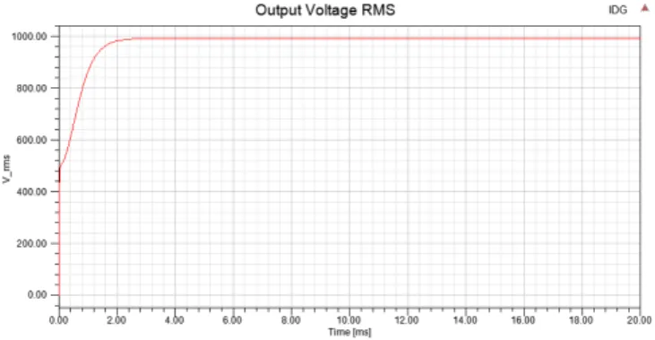
The electrical generator converts the mechanical energy into electrical energy and powers the electric system in the aircraft. Several essential components to build the integrated drive generator (IDG) are provided in the library, like con-stant speed drive (CSD), generator control unit (GCU) and generator with electrical excitation (EESG) and others [14]. The schematic of integrated drive generator example is shown in Fig. 3, the IDG output voltage RMS is shown in Fig. 4, which is regulated to the reference input of 1000 V. The output voltages of IDG are shown in Fig. 5.
D. Power Distribution
The generated electric power is distributed through the air-craft secondary system with power conversion devices. With specific demand from different loads, the electric energy need
Fig. 4. IDG Output Voltage RMS.
Fig. 5. IDG Output Voltages.
to be converted from AC to DC, DC to AC with different voltage level. The proposed library provides a convenient way to simulate the electric power distribution system with library components including boost, buck converters, DC/AC inverter and single phase, three phase rectifiers. Converters are based on system level devices with two modes, equiv andbehav. Inequivmode, the current through the switching device (IGBT/MOSFET) is determined by
Isw=
Vsw−Vf,sw
Rb,sw , Vsw > Vf,sw andctrl >0
Vsw
Rr,sw, otherwise
(17)
whereVswis the voltage across the device,Vf,swis the build-in forward voltage,Rb,swis the bulk resistance,Rr,sw is the reverse resistance. In behav mode, the current through the switching device is determined by
Isw =
Isat
Vsw Vt −50
exp(50), Vsw >0,Vsw Vt >50 andctrl >0
Isat
exp
Vsw Vt
−1
, Vsw >0,Vsw Vt ≤50 andctrl >0
Vsw
Rr,sw, otherwise
(18) where Isat is the saturation current, Vt is the threshold voltage.
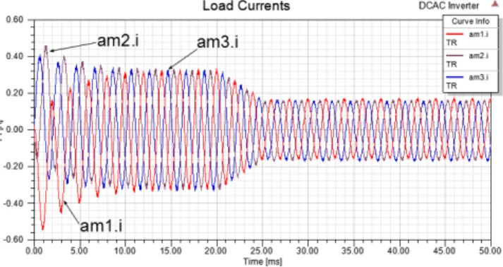
Fig. 6. Schematic of DC-AC Inverter with Ramp Change Duty Ratio.
Fig. 7. Load Currents of DC-AC Inverter with Ramp Change Duty Ratio.
connected through generic map and port map. A simple code example is shown in Listing 1.
... begin
c_front : entity basic_vhdlams.c(behav)
generic map (use_v0=>use_v0_front, v0=>v0_front )
port map (m=>m_in, p=>p_in, c=>c_front);
igbt1 : entity basic_vhdlams.igbt(equiv) generic map (rb=>igbt_rb, vf=>igbt_vf, rr=> igbt_rr, vt=>igbt_vt, isat=>igbt_isat) port map (e=>a_out, c=>p_in, ctrl=>igbt1); ...
Listing 1. VHDL-AMS Structral Modeling
A schematic to demonstrate the usage of three phase DC-AC inverter with embedded PWM controller is shown in Fig. 6. A ramp change of the duty ratio is applied to the PWM signal generator, the ramp changes from 1 to 0.5 starting at 0.02 sec within 0.005 sec. The frequency is set as 500 Hz and the front capacitor value is given as 1e-7 F. The output currents are shown in Fig. 7.
E. Load
Loads are the energy storage/consumption equipment to consume the distributed electric power. The proposed library provides couple of behavior level components for different scenario, including different type of batteries, constant power load, fan, motor and motor controllers, lamp, heater and so on. The dynamic behavior of battery discharging and charg-ing is modeled based on [27], [28]. Fig. 8 shows a simple circuit to test the dynamic charging and discharging behavior of a 12 V, 7.2Ah lead-acid battery model. A ramp change of the voltage source from 13V to 11V is applied starting at 20 sec within 2 sec, and the initial soc for the battery is set as 0.2. The charging and discharging performance is shown in Fig. 9. The permanent magnet synchronous
Fig. 8. Test Circuit for 12V, 7.2Ah Lead-Acid Battery Model.
Fig. 9. Charging and Discharging Behavior of 12V, 7.2Ah Lead-Acid Battery Model.
machine (PMSM) is modeled following [29]. Based on Park’s Transformation, abc to dq0 can be represented by
Va =Vdcos(φe)−Vqsin(φe) +V0 (19) Vb=Vdcos
φe−2
3π
−Vqsin
φe−2
3π
+V0 (20) Vc =Vdcos
φe+2 3π
−Vqsin
φe+2 3π
+V0 (21)
where φe is the electric angle, and it is p/2 times the mechanical angle φm, with pis the number of pole of the machine. The dynamic relations between the currents and voltages can be given by
LddId
dt =Vd−RsId+LqIqωe (22) LqdIq
dt =Vq−RsIq−(LdId+λpm)ωe (23) L0
dI0
dt =V0−RsI0 (24)
whereRs is the stator resistance,Ld andLq are the induc-tance of stator at d and q axis, respectively,λpmis the mutual flux linkage. The electric torque is calculated by
τ =3
4p[λpmIq+ (Ld−Lq)IdIq] (25)
and the rotor dynamics is given by
Imedωm
dt =τ (26)
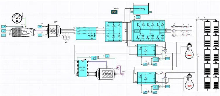
Fig. 10. Aircraft Electrical System Application Schematic.
III. APPLICATIONEXAMPLE ANDSIMULATION
The aircraft electrical library can be used to effectively build relatively large electrical power system. By combin-ing the components and subsystems described above, it is possible to simulate and analyze the mixed effects from the combination of high frequency switching power electronics devices and relatively slow environmental load control. The aircraft electrical system application schematic is shown in Figure 10. It contains the gas turbine subsystem and the integrated drive generator subsystem described in Section II-B and Section II-C, as well as components for power distribution, conversion and consumption.
There are five control loops in the system distribution and load side.
• The ramp change of the PWM duty ratio input of the
DC-AC inverter. At 0.1 sec, the duty ratio decreases from 1 to 0.5 within 0.02 sec.
• The PI control to maintain the output voltage of buck
converter A, which is the source of lamp A and buck converter B. The output voltage is kept at 220 V.
• The PI control to maintain the output voltage of buck
converter B, which is the source of lamp B and the battery pack. The output voltage is kept at 65 V. The battery pack is charging until the switch is turned off.
• The on/off control on the switch at the output of buck
converter 2. The switch is turn off at 0.2 sec, and after the switch turn off, the battery pack becomes the source of lamp B and start to discharge.
• The motor speed control through the DC-AC 3 phase
motor controller. The speed reference is changed from 1 rad/sec to 2 rad/sec at 0.15 sec within 0.01 sec. The output currents from the integrated drive generator subsystem are shown in Fig. 11. The amplitude of the currents changes due to the load side control changes.
The output currents from the DC-AC inverter are shown in Fig. 12. The currents decrease due to the ramp change of the PWM duty ratio start from 0.1 sec to 0.12 sec.
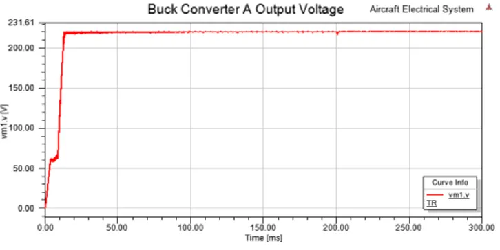
The buck converter A’s output voltage is shown in Fig. 13. The inner loop PI control regulates the voltage level for
Fig. 11. Integrated Drive Generator Output Currents.
Fig. 12. DC-AC Inverter Output Currents.
the loads of buck converter A, it keeps the same voltage as the switch on the buck converter B turns on/off. The buck converter B’s output voltage is shown in Fig. 14. The inner loop PI control keeps the voltage level for the loads of buck converter B until the switch turned off at 0.2 sec. After 0.2 sec, the voltage is mostly depends on the battery pack voltage, which will decrease as the battery discharges.
Fig. 13. Buck Converter A Output Voltage.
Fig. 14. Buck Converter B Output Voltage.
IV. CONCLUSION
The proposed aircraft electrical library provides the abil-ity to quickly prototype complex electrical generation and distribution system with multi-level, generic components. The reusability and the extensibility of VHDL-AMS make it relatively easy to modify and improve the system with more realistic components from experimental results. A demonstrative example using library components is discussed and the simulation results are presented.
REFERENCES
[1] M. Elbuluk and M. Kankam, “Potential start/generator technologies for future aerospace applications,” IEEE Aerospace and Electronic Systems Magazine, vol. 12, no. 5, pp. 24–31, 1997.
[2] J. Rosero, J. Ortega, E. Aldabas, and L. Romeral, “Moving towards a more electric aircraft,” IEEE Aerospace and Electronic Systems Magazine, vol. 22, no. 3, pp. 3–9, March 2007.
[3] R. Naayagi, “A review of more electric aircraft technology,” in
2013 International Conference on Energy Efficient Technologies for Sustainability (ICEETS), Nagercoil, April 2013, pp. 750–753. [4] A. Emadi and M. Ehsani, “Aircraft power systems: Technology, state
of the art, and future trends,”IEEE Aerospace and Electronic Systems Magazine, vol. 15, no. 1, pp. 28–32, January 2000.
Fig. 15. PMSM Speed.
Brighton, UK, September 2007, pp. 1007–1012.
[8] A. AbdElhafez and A. Forsyth, “A review of more-electric aircraft,” in13th International Conference on Aerospace Sciences & Aviation Technology, May 2009.
[9] K. Areerak, “Modeling and stability analysis of aircraft power sys-tems,” PhD Thesis, University of Nottingham, October 2009. [10] T. Jomier, “Moet technical report,” Airbus, Tech. Rep.
MOET-FP6-030861, December 2009.
[11] M. Sinnett, “787 no-bleed systems: saving fuel and enhancing opera-tional efficiencies,”Aero Quarterly, pp. 6–11, 2007.
[12] G. Gong, U. Drofenik, and J. Kolar, “12-pulse rectifier for more electric aircraft applications,” in Industrial Technology, 2003 IEEE International Conference on, vol. 2. IEEE, 2003, pp. 1096–1101. [13] A. Tantawy, X. Koutsoukos, and G. Biswas, “Aircraft power
genera-tors: hybrid modeling and simulation for fault detection,”Aerospace and Electronic Systems, IEEE Transactions on, vol. 48, no. 1, pp. 552–571, 2012.
[14] ——, “Aircraft ac generators: Hybrid system modeling and simu-lation,” inPrognostics and Health Management, 2008. PHM 2008. International Conference on. IEEE, 2008, pp. 1–11.
[15] Y. Ji and M. Kuhn, “Modeling and simulation of large scale power systems in more electric aircraft,” inControl and Modeling for Power Electronics (COMPEL), 2013 IEEE 14th Workshop on. IEEE, 2013, pp. 1–6.
[16] P. Ashenden, G. Peterson, and D. Teegarden,The System Designers Guide to VHDL-AMS. Morgan Kaufmann Publishers, 2003. [17] P. Voigt, G. Schrag, and G. Wachutka, “Microfluidic system modeling
using vhdl-ams and circuit simulation,” Microelectronics Journal, vol. 29, no. 11, pp. 791–797, 1998.
[18] K. Tsuji, Y. Kido, and T. Abe, “The application of vhdl-ams multi-domain hv simulation to the power performance and the fuel economy during warming up process,” SAE Technical Paper, Tech. Rep., 2011. [19] X. Li, S. Kher, and S. Lin, “Multi-domain system level behavioral hev library using vhdl-ams,” inElectric Vehicle Conference (IEVC), 2013 IEEE International. IEEE, 2013, pp. 1–5.
[20] A. Endemano, J. Fourniols, H. Camon, A. Marchese, S. Muratet, F. Bony, M. Dunnigan, M. Desmulliez, and G. Overton, “Vhdl– ams modelling and simulation of a planar electrostatic micromotor,”
Journal of Micromechanics and Microengineering, vol. 13, no. 5, p. 580, 2003.
[21] R. E. Quigley, “More electric aircraft,” inProceeding of 8th Annual Applied Power Electronics Conference and Exposition, March 1993, pp. 906–911.
[22] L. Faleiro, “Beyond the more electric aircraft,”Aerospace America, vol. 43, no. 9, pp. 35–40, 2005.
[23] A. F. El-Sayed,Aircraft propulsion and gas turbine engines. CRC Press, 2008.
[24] S. Yarlagadda, “Performance analysis of j85 turbojet engine matching thrust with reduced inlet pressure to the compressor,” Ph.D. disserta-tion, University of Toledo, 2010.
[25] G. Kopasakis, J. W. Connolly, D. E. Paxson, and P. Ma, “Volume dy-namics propulsion system modeling for supersonics vehicle research,”
Journal of Turbomachinery, vol. 132, no. 4, p. 041003, 2010. [26] G. Jian-hua and H. Ying-yun, “Modeling and simulation of an aero
turbojet engine with gasturb,” inIntelligence Science and Information Engineering (ISIE), 2011 International Conference on. IEEE, 2011, pp. 295–298.
[27] O. Tremblay and L.-A. Dessaint, “Experimental validation of a battery dynamic model for ev applications,”World Electric Vehicle Journal, vol. 3, no. 1, pp. 1–10, 2009.
[28] O. Tremblay, L.-A. Dessaint, and A.-I. Dekkiche, “A generic battery model for the dynamic simulation of hybrid electric vehicles,” in
Vehicle power and propulsion conference, 2007. VPPC 2007. IEEE. IEEE, 2007, pp. 284–289.