Abstract—In the coming days, most of the structures will be made with composite materials,. But the call of the day is optimum use of material to its fullest capability in terms of strength and life. In this sense, the support structure of any engineering products needs to satisfy the optimum use of material. One of the method is to carry out is through finite element analysis. In this particular study, the delamination effect on composite structures is analyzed with two models. Initially a composite plate subjected to uniformly distributed uniaxial load and later extended to intersecting cylindrical members. In the first model delamination is created by missing layer. The problem is analyzed for quarter domain due to symmetry. Later, discontinuity between the composite layers is created. The results are presented for both the problems. In both the cases increase in stresses is observed due to delamination which will create major problems during practical applications. This paper gives small insight of the problems created by delamination in the composites structures.
Index Terms- Composite Materials,FEM, Delamination, ANSYS
I. INTRODUCTION A. Composite materials
Composite materials are among the oldest and newest of structural materials. The older concept of composites is simply the mixing of two or more materials to rectify some short comings of a particular useful component. For example, early cannons, which had barrels made of wood, were bound with brass because a hallow cylinder of wood easily bursts under internal pressure. In ancient times, bricks were made up of clay and straw following this principle. Combination of straw and mud to make huts is still in use today in villages in our country. Similarly, ordinary steel covered with paint to protect it from rusting can be regarded as a composite. If this is regarded true, then almost all engineering materials are composites of some kind
Manuscript sent on Feb. 05, 2011; revised March 14, 2011.
Mohamed Haneef is with the Ghousia college of engineering,Ramanagaram, Karnataka State, India (phone: 9845142953; fax: 27273474; e-mail: [email protected]).
Shabbir Ahmed R M is with the Ghousia college of engineering,Ramanagaram, Karnataka State, India (phone: 9980114120; fax: 27273474; e-mail: [email protected]).
Mohammed Mohsin Ali is with the Ghousia college of engineering,Ramanagaram, Karnataka State, India (phone: 9880922905; fax: 27273474; e-mail: [email protected]).
B. Justification of definition
In order to justify the definition of advanced composite materials one can consider a more familiar example of fiberglass, which consists of glass fibers in resin matrix. Plastics are light, durable and easy to mould and show excellent corrosion resistance. They can easily be moulded into any complex shape with any desired color, finish and texture. However, plastics do not prove themselves to be sufficiently strong, stiff and dimensionally stable for their use in high performance load bearing applications. On the other hand, glass fibers possess very high strength, sufficient stiffness and durability, but lack in ductility and have a fibrous structure so that they cannot be used as such for any sort of load bearing application. By combining these two materials in the right way, glass fiber reinforced plastics (GRP) with all the good properties of both the components can be created. By proper composition and orientation of continuous fibers, it is possible to design a GRP of desired mechanical properties and functional characteristics. Such GRPs can be several times stronger than steel, almost as aluminum with a specific gravity of only one quarter that of steel.
C. Layered composites
Layered composites are composed of two or more different layers (called lamina) or sheets bonded together. The layers can differ in material (as in clad metals and bimetallic materials), form (as in sandwich materials such as honeycombs in which the core and facing material may or may not differ in form), and orientation (as in plywood in which the layers are the same but have different orientation of fibres).
By proper combination of constituting layers one can achieve a balance of such properties as light weight, high strength, high stiffness, wear resistance, corrosion resistance, unusual thermal expansion characteristics, appearance, etc. Properties of layered composites tend to be anisotropic and may vary from one side of the composite to other. Each layer may perform separate and distinct function. In addition, layered composites can incorporate the advantages of other composites. For example, the properties that can be achieved from the combination of fibres or particulates with metal, ceramic or polymer matrix can be utilized in combination with other materials used in the construction of layered composites. The individual layer itself can be a reinforced composite which is bonded by another resin. Some properties of the layered composites along the lamellae are estimated from the rule of mixture with negligible error. These properties include density, elastic modulus, electrical and thermal conductivity.
Studies on Delaminating Effects on Stress
Development in Composite Structures
Layered composites are broadly grouped into two categories:
(i) Laminated or laminar (ii) Sandwich composites
Laminar composite materials also include very thin coatings, thicker protective surfaces, claddings, bimetallics and many others. Laminates are generally produced by joining sheets or layers through an adhesive. Some important laminate composites include plywood, safety glass, and capacitor in which alternate conductor and insulator layers are bonded together.
Sandwich composites generally consist of a thick low-density core (such as a honeycomb or a foamed material) between thin facing layers of comparatively higher density. The primary aim of producing sandwich composite is to improve structural performance by improving strength to-weight ratio. In most of the instances neither of the components is strong or rigid and yet the resulting composite possesses these properties. A simple example of such composites is the corrugated cardboard which consists of a core of corrugated paper bonded on either side by flat thick paper. Neither of these is rigid but the combination displays this property.
II.LITERATURE SURVEY
Composites are mainly used to reduce the weight of the structure, as they give advantage of better strength to weight ration. Generally they find use with Helicopters, light air craft, commuter planes and sailplanes due to its advantage in low weight, high static and fatigue strength. In the coming days, most of the structures will be made with composite materials,. But there are certain problems with composites. Delamination is a common defect with composite structures. Delamination or separation of two adjacent plies in a composite laminate is one of the most common mode of damage. The presence of delamination may reduce the overall stiffness of the structure and resulting into failure. A clear understanding of the influence of delamination on the performance of the laminates is very essential to use them efficiently in structural design applications.
Delamination can occur during the preparation and production of composite parts or during machining, processing and assembly of the composite parts. . Delamination may occur from interlaminar stresses arising from geometric or material discontinuities from design features, such as an edge, a hole, a dropped ply.
Delamination can also occur due to the impact damage. The type of damage resulting from impact depends on the energy level involved in the impact. High energy impact such as ballistic damage results in through penetration with perhaps some minor local delamination. Low energy, medium or high velocity impact is likely to be caused by runway debris or hailstones. This doesn’t produce penetration. This may result in some local damage on the surface together with delamination within the structure and fiber fracture on the back face. The presence of delamination is of major concern in compressively loaded components where the delamination may grow under fatigue loading by out of plane distortion.
Delamination also lower the buckling factor of the composite panels. Primary air craft components like wing, shear wall panels and skin area of the aircraft that are supported by ribs are designed for high buckling loads. The threat of delamination arising from in service loading has been one of the factors in limiting the adoption of laminated composite material in greater volume for primary structure. While other damage modes such as matrix cracks may occur first, delamination result in larger stiffness drops and reduction in load bearing capabilities
Ronald Krueger[1] et al, developed a shell/3D modeling technique was developed for which a local solid finite element model is used only in the immediate vicinity of the delamination front. The goal was to combine the accuracy of the full three dimensional solution with the computational efficiency of a shell finite element model. Multipoint constraints provided a kinematically compatible interface between the local 3D model and the global structural model which has been meshed with shell finite elements.
D.M. Kim et al,[2] investigated the influence of inter-laminar shear stress on mode II free – edge Delamination at the free edge in composite laminate is studied experimentally and analytically. Delamination tests are conducted under uni-axial compressive load to eliminate transverse cracking test laminates are designed to have compressive inter-laminar normal stress and various ratios of inter-laminar shear stresses at the interfaces of interest
H.V. Lakshminarayana et al[3] presented numerical simulation of static indentation. Also impact tests of laminated composite plates, using a commercial finite element system are presented. Extensive results from a parametric study are also provided to supplement the experimental result.
S.P. Joshi et al [4] has investigated the experimental data of the three dimensional problem of impact of a flat strip by a spherical impact are presented and interpreted qualitatively by comparison with a plane strain numerical analysis of an infinitely wide plate impacted by a cylindrical member. The role of transverse shear stresses in proximal and middle layer crack initiation is established.
III.PROBLEM DEFINITION & SCOPE OF PRESENT INVESTIGATION
Definition: The objective is to study the change of stress in composites by delamination process. This delamination is created by missing fly or discontinuous layer formation.
Scope of the present work:
Modeling of the general composite structures
Meshing of the problem using Linear layer shell element Solving the problem with and with out delamination of layer composites and analyzing the results.
Methodology
Two models are considered for studying the delamination effects. The first model is built with 4 layers of composite
uni axial loads.Delamination is given to some layers and problem is solved.
The results are compared.
In the second case composite cylinders of intersection is considered. Both the cylinders are analysed with and without delamination.Also problem is extended for crack development due to delamination.
Assumptions
The materials considered are Orthotropic materials
Delamination is created by missing layers and disconnected layers. All FEM approximations are applied
for the problem.
IV. RESULTS AND DISCUSSION
The delamination effects are analysed for stress development in the composite structures due missing ply and discontinuous layer. The study has been done for the following cases:
Composite members subjected to uniaxial loads.
Intersecting composite cylinders subjected to vertical loads Disconnected composite cylinders due to delamination Two Orthotropic materials are considered for analysis. The material properties are as follows.
Table 1: Material properties Description Material 1
(Mpa)
Material 2 (Mpa)
E11 50000 190000
E22 12000 7700
E33 12000 7700
12 .3 .3
23 .3 .3
13 .3 .3
G12 5600 4200
G23 5600 4200
G13 5600 4200
MODEL 1: (Composite plate subjected uniaxial load) A Composite plate subjected to uniaxial load is considered to study the effect of delamination (Here delamination is created by missing layer). A pressure load of 1 N/mm2 is applied at the end of the plate. The results are as
follows.
Fig 3.1: Boundary conditions of the problem
The fig 3.1 represents applied boundary conditions for the problem. Map meshing is used for mesh. Linear layer
shell99 is used for meshing. Totally 4 layers of thickness equal to 0.5mm is considered.
Fig 3.2: Layer orientation of the problem
The fig 3.2 shows layer form of composite. Left shows angular orientation and right side materials. Here two materials in sequence are used to form the composite. Vertical lines shows angular 900 orientation of layer and horizontal lines show orientation in 0 0.
Fig 3.3 Displacement pattern of the problem The figure 3.3 shows displacement in the structure.
Maximum displacement is around 0.002702 mm.The colors show varied displacement patter in the system for uniaxial loads.
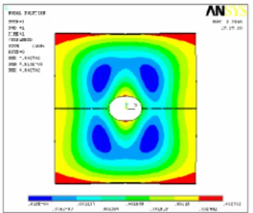
Fig 3.4 Vonmises stress in the member Figure 3.4 shows vonmises stress in the structure. Maximum stresses are located by color red. The color Pattern shows varied stress across the section
Figure 3.5 shows Stress concentration in the problem. Maximum stress of 6.261 can be observed at the left end in the 2nd layer.
Fig 3.6 Delaminated layer representation
Delamination is introduced in the maximum stress concentration region. The delamination layer structure is as shown below. Fig 3.6 shows delamination in the structure. Third layer is made dummy or missing in the composite structure. The effect of this on stress results are given below.
Fig 3.7 Delamination region
Fig 3.7 shows delamination of the composite layer. Here one layer is dropped from the formation.
Fig 3.8 Vonmises Stress distribution in the structure. Fig 3.8 shows vonmises stress in the structure. Due to delamination stress is increased to 7.858 N/mm2
Fig 3.9 Stress concentration in the problem
Fig 3.9 shows change of stress value and location of stress. The maximum stress region is delaminated , so the region concentration is changed along with increase in stress
Fig 3.10: Maximum displacement in the structure Fig 3.10 shows displacement pattern in the structure. The displacement values are increased compared to undelaminated structure.
MODEL 2: Intersecting cylinders
Two intersecting composite cylinders of 50 mm length and 20mm diameter are considered to study delamination effect. The geometry is as shown below.
Fig 3.11: Model dimensions
Fig 3.11 shows intersecting composite cylinders with dimensions. This has been considered due to the importance of junctions in many structural parts. Generally these regions are more subjected to stress concentration. Any stress increase in these regions lead to reduction of the life of members.
Figure below shows meshed plot of the problem. Here a linear layer Shell99 is considered for analysis. This shell element can take up to 250 layers of composite with 6 degrees of freedom.
Fig 3.13 Boundary Conditions of the problem
The above picture shows composite cylinders boundary conditions. The cylinders are fixed at the bottom and a vertical load of 400 N is applied which is distributed to the structure along nodal boundary.
Fig 3.14 Layer orientation of the problem
Figure 3.14 shows layered configuration of the problem. Again same materials applied for previous problem are considered with the same orientation.
Fig 3.15 Vonmises Stress in the Structure
Figure 3.15 shows vonmises stress in the structure. Maximum stress pattern is shown by color red which represents maximum value of 10.427 N/mm2. Maximum displacement in the structure is around 0.003876 mm With delamination
Fig 3.16 Delamination region
Figure 3.16 shows delamination region where third layer is missing. The effect of this is analysed as follows.
Fig 3.17: Stress Increase in the problem
Fig 3.17 shows stress variation due to delamination of composite. The above picture shows stress increase compared to undelaminated structure. Maximum stress is raised to 11.245 N/mm2 from 10.427 N/mm2
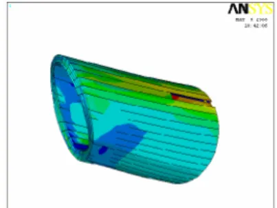
Fig 3.18: Three Dimensional representation of the Problem
The above picture shows in 3 dimensional view, the delaminated region and stress region in color red. Only right side cylinder is shown in the picture.
MODEL 3: Delamination by discontinuous Layer formation Here the discontinuous layer formation is considered on the top. Due to the discontinuity in the problem, crack will be generated in the problem.
Fig 3.19: Deformation in the structure due to discontinuity in the layer .
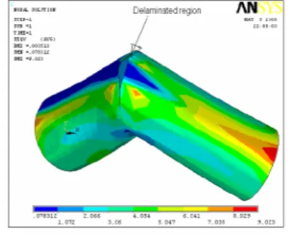
Fig 3.20 Crack formation in the structure
Figure 3.20 shows crack formation in the composite cylinders due to discontinuity in the layer formation. Maximum stresses are around 9.023 N/mm2. Here stress
regions are scattered.
For the same boundary conditions, the vonmises for undelaminated structure is as follows
Fig 3.21 vonmises Stress for undelaminated structure Figure 3.21 shows undelaminated structure with continuity of the layer structure. Here stress regions are continuous unlike delaminated structure.
V. CONCLUSION
The delamination effect on composite structures is analyzed with two models. Initially a composite plate subjected to uniformly distributed uniaxial load. Later study has been extended to composite structures. The results and its conclusions are as follows.
A square composite plate of 100mmX100 mm is considered for uni-axial load case. 4 layers made of two different material and orientation are considered for the analysis. Due to symmetry of load and geometry, only quarter plate is modified and meshed with 8 noded linear layer Shell99 elements.
The results for undelaminated structure presented for vonmises and deformation
Delamination is introduced in the high stress concentration region, and the effects are studied.
1. The results shows increase in stress and change of location of maximum stress
2. Again intersecting composite cylinders with the same material properties, orientation are considered for analysis.
3. Initially undelaminated composite cylinders are analyzed 400 N vertical loads and the results are presented. 4. Delamination is introduced in the member again at higher stress region. The results are presented for delaminated 5. Structure. Concentrated stress regions are represented. 6. Finally in the same intersecting composite cylinders, delamination is created by discontinuity across the layers. The results shows opening of the structure under the given loading conditions.
7. All the results are presented with necessary pictures. REFERENCES
[1] Ronald Krueger and T. Kevin O’Brien, “A Shell/3D Modeling Technique for the Analysis of Delaminated Composite Laminates” NASA/TM-2000-210287ARL- TR-2207.
[2] D.M. Kim and C.S. Hong, “Mode II Free Edge Delamination in Laminated Composites under uniaxial Compression”
[3] H.V. Lakshminarayana, R. Boukhili & R. Gauvin, “Finite Element simulation of Impact tests of laminated Composite plates “Department of Mechanical Engineering. Ecole Poly techniques de montreal, Canada.
[4] S.P. Joshi and C.t. Sun, “ Impact induced Fracture in a Laminated Composite” , Journal of Composite Materials, Vol 19 pp 51-65 January 1985.
[5] K.L. Sing , B. Dattaguru, T.S. Ramamurthy and P.D. Mangalagiri “Delamination tolerancestudies in laminated composite panels” Sadhana A, Vol 25, Part4, August 2000, pp.409-422
[6] Shigley, Joseph E., Mechanical Engineering Design, McGraw-Hill, edition, 2001.
[7] Finite Element Procedures – Klaus-Jurgen Bathe, Prentice Hall of India Pvt. Ltd.- Sixth Edition 2002. [8] Introduction to the Finite Element Method, Desai/Abel
– CBS publishers 2002.
[9] Concepts and Application of Finite Element Analysis Robert D. Cook, David S. John Wiely & Sons Pvt. Ltd. Fourth Edition 2003.
[10] ” A review of meshless methods for laminated and functionally graded plates and shells” K.M. Liew, Xin Zhao a and Antonio J.M. Ferreira.
www.elsevier.com/locate/compstruct
[11] “Thermoplastic and duromere fiber reinforced composite components and hybrid structures” http://www.st.dlr.de/BK
[12] “Depending upon the type of failure the model may be Used to model composite laminates”.