A R C H I V E S
o f
F O U N D R Y E N G I N E E R I N G
Published quarterly as the organ of the Foundry Commission of the Polish Academy of Sciences
ISSN (1897-3310)
Volume 10
Issue Special1/2010
451−454
89/1
The friction influence on stress
in micro extrusion
J. Piwnik, K. Mogielnicki*
The Department of Production Engineering, Bialystok Technical University – Wiejska street 45 C 15-351 Bialystok, Poland
*correspondence address: e-mail: [email protected]
Received: 26.02.2010; accepted in revised form: 30.03.2010
Abstract
Manufacturing of metallic parts by forming methods is industrially widespread due to high production rate, high accuracy, dimension’s and shape’s repeatability and good surface quality. The application of metal extrusion methods for the production of micro parts is possible, but there are some technological problems caused by small dimensions. Size effect is appearing. One of size effect symptom in micro extrusion, is a significant influence of rough contact between workpiece and tool while processing. In the case of rough contact without friction, material flows in the vicinity of the die surface. In order to explain more accurately a friction distribution in this area, the plastic wave friction model is proposed. This paper analyses specifications of a metal extrusion in micro scale. Using the friction model, a substitute friction shear factor mz and its influence on extrusion loading curves is determined in relationship to size of asperities.
Key words: Mechanical property; Micro extrusion; Rough friction, FEM simulation;
1. Introduction
Micro extrusion is a new production method for metallic small items with two dimensions less than 1mm [1] by forming technology. Reducing sizes of manufactured objects to micro scale, some of process parameters, such as for example grain size or surface roughness remain unchanged, that cause appearing so-called size effect [2]. Top layer texture depends on sort of surface treatment which has been subjected to adaptability or obtain the intended structure. It should be also keep in mind, that its quality is related to material grain size [3]. Because of the fact, that the surface roughness is part size independent and does not decreases with miniaturization [4], numerical simulations processes should be adapted to the requirements of level micro. During the forming of small details by extruding, fundamental issue is to precise friction conditions between the material and the tool. Size effect should be considered.
Qualitative friction distribution and its quantitative parameters directly affects on size effect. Compared to macro, micro extrusion is characterized by different stresses distribution in
adhesive layers of the interface. This article presents the interface workpiece – tool structure geometry numerical modeling methodology with use triangular wave. The model is intended to allow getting more realistic simulation results of the plastic treatment processes in micro scale, using not too much complicated procedure.
2. Summary of the theory
In metal forming processes, two laws describing the impact of stresses and deformations on friction conditions are commonly used:
• Coulomb Law – describing the friction in elastic range:
(1)
where: τf – frictional stress, N - normal force, Ff - frictional force,
A - contact area, µ - friction coefficient;
• Constant Shear Stress Law – for plastic friction:
(2)
where: τf – frictional stress, m – friction shear factor 0≤m≤1,
f – friction factor, k – shear yield strength, –stress effective; Friction model for rough contact of plastic material with rigid tool has been presented in [5]. It is based on a simplified top layer geometry of the tool, which represents actual profile. Its length AR and height R, are the average parameters obtained from roughness profile (fig. 1).
Fig. 1. Triangular asperity [5]
In considerations, perfectly plastic material, deformed under impact of roughness, were used – plastic wave friction model. Distribution of friction on the workpiece – tool interface looks like a mix of the Coulomb and Tresca laws with a friction coefficient sensitive to the angle α of the tool asperity.
3. Numerical experiment procedure
3.1. Factual and theoretical roughness
Holes in micro extrusion tool’s containers are finished by polishing. Obtained in this way roughness Rz may vary 20 – 10µm
while initial polishing and 6,3 – 1,6µm while finish. Growth of roughness importance in micro scale, causes changes in friction conditions at the interface workpiece – tool while plastic treatment compared to traditional macro forming, where roughness influence on the process is relatively small.
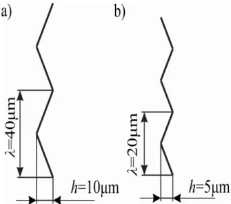
To determine the distribution of friction in micro scale and its impact on the extrusion forces, roughness numerical model surfaces of container 1mm in diameter and right-angled die with diameter reduction 1/2, for rod forward extrusion has been created (fig. 2). This model is the triangular wave in two variants. In the first case its height h = 10µm and lengthλ = 40µm represents the average height of roughness achieved during initial polishing. In the second, height h = 5µm and length λ = 20µm simulates the surface layer after the finish polishing (fig. 3).
Fig. 2. a) Layout for metal rod forward extruding, b) model of container and die roughness with taking in to account size effect
Fig. 3. Investigated parameters of triangular asperity; a) average roughness obtained while initial polishing, b) average roughness obtained while finish polishing
3.2. Numerical model assumptions
Axisymmetric geometry of the investigated processes, allows considering one half of the billet, reducing calculation time this way. To carry out the simulation processes, DEFORM software was used. The billet material was considered as a plastic with the strain hardening defined on fig. 4. The mesh of the billet was fine enough to take into account all the asperities of the interface. As well as die, container and punch were treated as a rigid.
Fig. 4.Stress-strain curve of the workpiece material
At the interface, a rough layer of a tool – workpiece, a zero friction shear factor m has been given. This assumption gave a possibility to observe a flow of a extruded material along triangle roughness wave without conventional friction disturbance. In that case, resistance of the rigid asperity to billet movement was treated as a friction. To determine the distribution of friction along the wall of the container, substitute friction shear factor mz
has been calculated. A measure of its concentration is the ratio of frictional stress to shear yield strength – Constant Shear Stress Law, located on an agreed level of wavelength, while extension flow of the material.
where:
In this work, the measurement line x has been placed on the peaks of asperities (fig. 5). Such points distribution, in the number of 1000, allowed to specify stress values in the most sensitive area of the contact layers.
Fig. 5. Location and direction of the measurement line
3.3. Study results
During the simulation of rod forward micro extruding characterized by wave h = 10µm and λ = 40µm, at the interface billet – container, following distributions of effective (fig. 6) and friction τf (fig. 7) stressdistributions has been obtained.
Fig. 6. Effective stress at the contact with triangular wave h=10µm, λ=40µm; left: solid contour, right: distribution at x length
Fig. 7. Friction stress τf at the contact with triangular wave
h=10µm, λ=40µm; left: solid contour, right: distribution at x length
As well as effective, friction stress are characterized by specific distribution in triangular wave vicinity. Value of increases with increasing container height x. Parameter τf varies
by obtaining a partially negative values, which is a friction stresses direction changes signal.
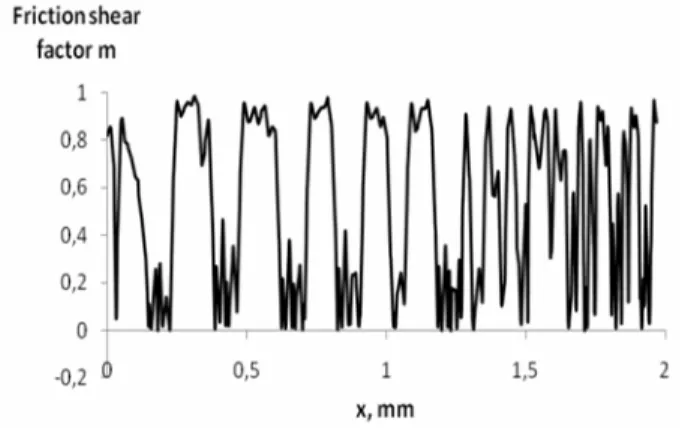
Using the equation (3) the substitute friction factor mz has
been obtained. Distribution of this parameter at the height of the container wall x shows fig. 8. Similarly to τf, friction factor mz
oscillates along x length. Its value is contained between 0 and 1.
Fig. 8. Distribution of the substitute friction shear factor mz at the
height of the container wall x, characterized by triangle wave h=10µm, λ=40µm
Analogously as in previous case, rod forward micro extrusion using the tool characterized by wave h=5µm and
λ=20µm, were conducted. While simulation, contact distributions of effective and friction stress has been obtained, and the substitute friction factor mz at the x length has been calculated –
fig. 9.
Fig. 9. Distribution of the substitute friction shear factor mz at the
height of the container wall x, characterized by triangle wave h=5µm, λ=20µm
Reducing wave parameters, decreases induced by it impact of effective stress at the cross-section of extruded material. Substitute factor mz reviled greater frequency of maximum
deflection than in the previous case.
Dependence of extrusion forces from size of asperities presents fig. 10. For comparison, loading curve obtained during extruding the same billet in the flat container with a constant friction factor m = 0.12 (without wave model) is located. Distribution of obtained extrusion loading curves clearly indicates growth of forces with increasing wave parameters.
Fig. 10. Effect of triangle wave of the container asperities on extrusion loading curves
4. Conclusions
Characteristic distribution of effective and friction stresses at the interface with rigid wave, causes changes of friction conditions during micro extruding. Substitute friction shear factor mz gives a possibility to illustrate the frictional forces distribution
value on a rigid rough tool – workpiece interface. The smaller the height of roughness, the greater the factor mz frequency
fluctuations. This phenomenon is dictated by increasing variability values of the contact friction stress τf with increasing
the frequency of the wave.
The wave model reveals increase of friction shear factor m values at the interface in micro scale. Its presence affects the level of extrusion forces. The higher wave height while the same process, requires the higher extrusion forces. Increased demand for forces may also be explained by hardening of deformed material under roughness impact. This phenomenon does not occur at traditional macro extrusion and may be treated as size effect.
References
[1]U. Engel, R. Eckstein, Microforming – from basic research to its realization, Journal of Materials Processing Technology 2002.
[2]J. Piwnik, K. Mogielnicki, K. Garbala, Problems related to micro – extrusion process, Aparatura Badawcza i Dydaktyczna, 2010 (in Polish).
[3] N. Krishnan, J. Cao, K. Dohda, Microforming: Study of friction conditions and the impact of low friction/high strength die coatings on the extrusion of micropins, ASME Journal of Manufacturing Science and Engineering, 129, 2007.
[4] E. Vidal-Sallé, S. Boutabba, Y. Cui, J.C. Boyer, An improved plastic wave friction model for rough contact in axisymmetric modeling of bulk forming processes, International Journal of Material Forming, 2008.
[5]J.M. Challen, and P.L.B. Oxley, An explanation of the different regimes of friction and wear using asperity deformation models, Wear 53 , 1979.