358
REAL IMPACT OF THE THERMAL INERTIA ON THE INTERNAL
AMBIENT TEMPERATURE OF THE BUILDING IN THE HOT HUMID
CLIMATE: SIMULATION AND EXPERIMENTAL STUDY IN THE CITY
OF DOUALA IN CAMEROON
Alexis Kemajou1* & Léopold Mba2
1,2 Laboratory of Refrigeration and Air Conditioning;Advanced Teachers Training College for Technical Education
- University of Douala, P.O. Box. 1872 Douala Cameroon. *Corresponding author: Tel: (+237) 77 76 74 80/96 88 68 13
E-mail: [email protected]; [email protected]
ABSTRACT
Many studies, have demonstrated that the use of thermal inertia can usefully modify the thermophysical signature of buildings. However, their influences under hot-humid climate with local building materials in Africa have not been investigated in details. This work is based on the experimental and simulation of the thermal inertia of traditional buildings with wooden walls and modern buildings with hallow concrete block walls in hot humid climate. Before simulation, a finite difference method is applied to the equation of heat transfer and a thermal network of the building was realized. A calculation code developed with the matlab software was used for the simulation and a data acquisition apparatus is used for acquisition, stocking and treatment of data. Experimental study carried out during the month of may 2011 permitted us to validate a numerical model. Analyzing the experimental study shows: a zero time lag and temperature depreciation of 0.5°C between the external and the internal walls of the wooden buildings; a time lag of 04h15min and temperature depreciation of 1.5°C between the external and the internal walls of hallow concrete block buildings. The study reveals that traditional buildings with low thermal inertia like wooden assure better thermal comfort for non air-conditioned buildings in hot humid climate region.
Keywords: thermal inertia, building materials, hot humid zone, matlab software, simulation, experimentation
1. INTRODUCTION
Energy auditing of certain modern buildings and others similar studies [1-7] are carry out. The results show that modern buildings are sources of excessive energy consumption, and they provide also the thermal discomfort. In 2001, a survey conducted in Cameroon, by the National Institute of Statistics (INS) [8] shows that because of poverty in this country, three out of four households live in buildings with the walls made up of materials such as the wooden, bricks of earth, and others. The survey carry out also shows that in the city of Douala in Cameroon, where the climate is hot and humid, 52.6% of buildings have a wall made up of wooden, 34.4% of building have a wall made up of hollow concrete blocks, and 13% in various materials like stones, brick of earth. These building materials are particularly characterized by their resistance and thermal inertia. Some works [9-13] show that the thermal inertia of building materials plays an important role in the thermal comfort of the buildings. These studies suggest a design strategy of buildings below in the hot climate: for the equatorial climate which is very nice, to research the internal ambient conditions similar to those outside by choosing a solar protection, a slight thermal inertia and permanent ventilation; for the tropical climate where peak temperatures make outside conditions uncomfortable, to decouple the internal conditions of those outside by choosing a solar protection thrust, high thermal mass and night air ventilation. Fezzioui et al. [14] have studied the influence of the characteristics of the
building envelope on thermal comfort. The walls consist of double-wall built with hallow concrete block with plaster coating to the internal wall surface and coated cement mortar on the outside wall surface. They have introduced elements to improve thermal comfort, such as to increase: thermal inertia; insulation of exterior wall surfaces, roof; and window surface. Medjelekh et al. [15] have evaluated the impact of the thermal inertia on the
359
is also, a great absorber of energy. According to Givoni [17], thermal inertia is a necessary recommendation for the construction in warm climates with a large diurnal variation of temperature. Goulart [18] states that the thermal inertia may also be useful in the hot humid climate. Kemajou et al. [19] have studied the impact of the choice of
building materials on the thermal comfort in the hot climates. They highlight the local building materials suitable for different climatic regions in Cameroon. Many studies, have demonstrated that the use of thermal inertia can usefully modify the thermophysical signature of buildings. However, their influences under hot-humid climate with local building materials in Africa have not been investigated in details.
The purpose of this study is to examine the real impact of the thermal inertia on the internal ambient temperature of traditional and modern buildings in hot humid climate, through modeling, simulation and experimentation.
2. MATERIAL AND METHOD 2.1. Material
2.1.1. Climatic Conditions of Study Area
Cameroon stretches the length of the 2nd to the 13th degree of north latitude, and extends horizontally from the 9th to the 16th degree of longitude. It covers an area of 475,442 km2 and has various types of climate, with its varied soils, summarizes the major biogeographic units of the African continent [20, 21].
The work is carried out in the town of Douala, Cameroon's economic capital, located on the Gulf of Guinea and the
estuary of the Wouri Sea. Its longitude is 09°44‟ East and latitude 04°01 North. The city altitude is 5 meters. The
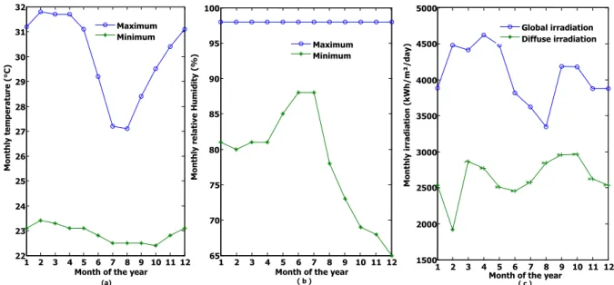
prevailing wind direction is south-west and its speed average varies between 1.8 m/s and 3.0 m/s [20-23]. Monthly averages of temperature, relative humidity and irradiation are shown in Figure 1 below. In this figure, the mean monthly maximum temperature varies between 27.1°C and 31.8°C, while the minimum monthly average ranged from 22.4°C and 23.4°C. The relative humidity remains almost constant throughout the year in the range of 68% and 98%. Precipitation amounts to 4500 mm per year.
Figure 1. Climate data from the city of Douala. (a) Temperature, (b) Relative humidity, (c) Irradiation
2.1.2. Experimental Buildings
According to the results of a survey conducted in Cameroon in 2001, by the National Statistics Institute (INS) [8], 52.6% of buildings hhave a wall made up of wooden and 34.4% of building have a wall made up of hollow concrete blocks. For this reason, buildings with hollow concrete blocks envelopes and those made up of wooden were selected for the study. These buildings have in common, the aluminum sheet for roofing painted red, the floor made up of cement, a false ceiling non-ventilated, made up of plywood, and face the same external climatic conditions. The windows are operable but usually remain closed. The room height is 3 m. One bedroom of 15 m² is used to the experimentation.
The comparison criterion chosen is the type of building material for walls. These materials are wooden and hollow concrete block coated with cement mortar. Buildings undergo physical phenomena that can be represented by mathematical equations.
1 2 3 4 5 6 7 8 9 101112 22
23 24 25 26 27 28 29 30 31 32
Month of the year
M
o
nt
hly
te
m
p
e
rat
u
re
(
°C
)
(°C
)
1 2 3 4 5 6 7 8 9 10 11 12 65
70 75 80 85 90 95 100
Month of the year
M
o
nt
hly
re
lat
ive
H
um
id
it
y
(
%
)
1 2 3 4 5 6 7 8 9 10 11 12 1500
2000 2500 3000 3500 4000 4500 5000
Month of the year
M
o
nt
hly
ir
rad
ia
tion
(k
W
h/
m
²/
d
ay
)
(k
W
h/
m
²/
d
ay
)
Global irradiation Diffuse irradiation Maximum
Minimum Maximum
Minimum
360 2.1.3. Equipments Used
Instrumentation (figure 5) was used to record the air temperatures in the experimentation area and the outside air
temperature. The measurement apparatus was made up of the following: a laptop computer equipped with the “DAQ Factory software for the “LABJACK” parameters; a data acquisition apparatus “LABJACK U3”; temperature
sensors.
.
Figure 2: diagram for data acquisition chain
The characteristics of the temperature sensors are given in table 1.
Table 1. Characteristics of temperature sensors
Type Temperature range Response time Uncertainly Cable length
EI-1034 -17 to 150°C 20s ±0.4°F 1m90
Six temperature sensors are installed at the experimentation area. Temperatures are captured hourly, then processed and stored in the computer with the data acquisition system. Concerning the database, the series of experimental values of two characteristic quantities were obtained, i.e. the outdoor air and the indoor air temperatures.
2.2. Method
2.2.1. Thermal Model of the Wall of the Building
Thermal modeling consists of putting into equation the phenomenon of heat transfer through the walls of a building and the indoor climate.
For a typical room in the building, the following assumptions were made: one directional heat flow ; thermal properties of the building materials are homogeneous; the properties of the airstream flowing over the surface of the building structures are homogeneous; during the operating period, the heat capacity of the space air is small compared with other heat gains, therefore it can be ignored; the temperature of the concrete floor is equal to the internal temperature while neglecting the heat exchange between them.
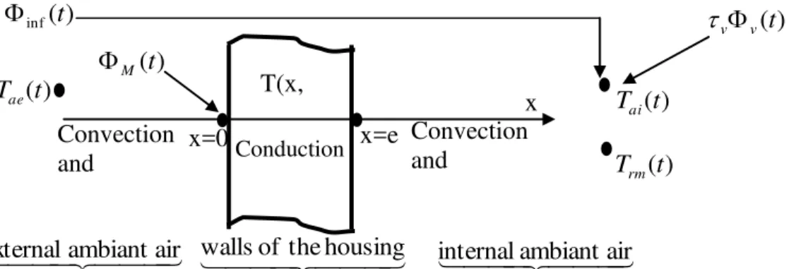
The wall is represented by the figure below.
Figure 3. Thermal model of the wall of the building
Ambient to be study Temperature sensor « Universal temperature probe MODEL EI-1034 »
Transmitters « LABJACK U3 module »
Stocking and treatment of data
T(x,
t)
x=0
x=e
x
Convection
and
radiation
Convection
and
radiation
Conduction
)
(
inft
)
(
t
T
ae)
(
t
M
)
(
t
v
v
)
(
t
T
ai)
(
t
T
rm
ambiant
air
internal
of
the
housing
walls
ambiant
air
361
In this figure, Tae (t) and Tai (t) represents respectively, the temperature of the external and internal ambient air of the building. T(x,t) is the temperature through the wall, x and e represent the thickness of the wall, t is the time.
ΦM(t) is the heat receive by the external wall of the building. ΦV(t) is the heat due to solar flux. Φinf (t) is the sensible heat gain from infiltration of air in the building. τV represent the transmission coefficient of glass.
)]
(
)
(
[
inf
q
v asc
asT
ait
T
aet
(1) Where
q
vis the volume flow rate,
asis the density of external air andc
as the thermalcapacity of infiltrated air. The governing equation of heat transfer through the walls of building [25-27] is given by
)]
(
)
,
(
[
)]
(
)
,
(
[
)]
(
)
,
0
(
)[
(
)
(
0
1
0 2 2t
T
t
e
T
hri
t
T
t
e
T
hci
x
T
t
T
t
T
hre
hce
t
x
T
t
T
a
x
T
rm ai e x ae M x
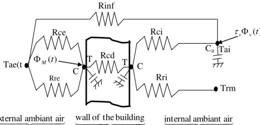
(2)Where hce, hci, hre, hri are respectively, the coefficients of external convection, internal convection, external radiation and internal radiation. Trm (t) is the mean radiant temperature of a room. To solve this equation (2) with boundary conditions, a finite difference model is developed. The principle here is that of the finite difference method (FDM) as seen in some models of thermal simulation of walls like MINERVE [28] and CoDyBa [29-31]). Each domain of the wall is discretised into a number of nodes on which temperatures and thermal capacitances are associated. On each node, an instant heat balance is done. According to its position, the node exchanges conductive, radiative or convective heat flux with neighboring nodes or its environment. The node network obtained is assimilated to an electrical circuit where each node is linked to one or many nodes by electrical resistances R or conductances K (where K=1/R), with a capacitance C. By using FDM, the figure 3 becomes the thermal network of the wall as shown in the figure 4 below.
Figure 4. Thermal network of a wall of the building
In this figure, Rce, Rre, Rci, Rri, Rinf, Rcd are the thermal resistances due respectively to the external
convection, external radiation, internal convection, internal radiation, infiltration of external air and conduction through the wall. CE, CI, Cai are respectively, the thermal capacitances of the external surface node, internal surface
node and internal air of room. TE and TI are the temperatures of external and internal surface node of wall.
For one dimensional heat flow, the energy balance at external surface node (E) and internal surface node (I) of the partition walls respectively.
At external surface node E
)
(
t
v v
C
C
Tai
(t)
Tae(t
)
Rci
Rcd
Trm
(t)
Rce
Rre
Rri
Ca
T
T
Rinf
)
(
t
M
ambiant
air
internal
of
the
building
wall
ambiant
air
362
)
(
)
(
)
1
(
)
(
)
1
(
)
(
)
1
(
)
(
)
1
1
1
(
t
t
T
R
t
T
R
t
T
R
t
T
R
R
R
dt
dT
C
M I cd ae ce ae re E cd ce re E E
(3)
At internal surface node I
)
(
)
1
(
)
(
)
1
(
)
(
)
1
(
)
(
)
1
1
1
(
T
t
R
t
T
R
t
T
R
t
T
R
R
R
dt
dT
C
E cd ai ci rm ri I cd ci ri II
(4)
For ambient air, we have
)
(
)
(
1
)
(
R
1
)
(
1
1
)
(
inf n 1 i ci inf 1t
t
T
R
t
T
t
T
R
R
dt
t
dT
C
v v ae i I ai n i i ci ai ai
(5)
in1ri
1
R
(
)
1
)
(
1
0
i I rm n i i cit
T
t
T
R
(6) Where n is the number of walls of the building.
The equations (3), (4), (5) and (6) are applied to the walls, the ceiling, the windows, the roof of the building, and indoor ambient air.
From each node of the building a first order differential equation is obtained. The system of equations due to all nodes of the building is written in a matrix form as:
)
(
B
)
(
)
(
t
t
T
K
dt
t
dT
C
(7)
T (t): column vector of temperatures at the different nodes with “t” being the time parameter. C: column vector of capacitances at the different nodes
K: square matrix constituting of thermal conductances B: matrix of coefficient on the different nodes
Ф(t): Column vector of excitation (external temperature, internal heat load, solar flux) The different coefficients C and K are calculated from the values given in Tables 2 and 3.
Table 2. Convection and radiation heat transfer coefficients [23]
Thermal coefficient of heat transfer (w/m²k) External wall Glass wall
Walls Ceiling
External convective and radiative coefficient (hrce) 20 20 16.7
Internal radiation (hri) 5 6.1 5
External convection (hci) 3 2 4.05
This table gives the data used to calculate the thermal conductance due to convection and radiative heat transfer.
Table 3. Thermodynamic properties of building materials [32, 33]
Material Thermal conductivity (w/m k) Density
(kg/m3) Heat capacity (kJ/kg k)
Plywood 0.14 600 2.720
Cement coating 1.15 1800-2100 0.800
Cement block 0.67 1250 0.880
Aluminum roofing sheet 70 7800 0.800
Wood 0.121 300-750 2.510
Glass 1.15 840 1.602
363
Solving the system of equations (7) below is done after time discretisation. In this model, the equations of heat transfer in the building is modeled with a finite difference scheme and solved with an explicit method. The new system of equations obtained is:
(
)
(
t
t)
2
1
)
(
t)
(
1
1
B
t
B
t
T
t
T
(8)With
K
t
C
2
1
,K
t
C
2
1
and
t
is the time step which is one hour.After this step, a calculation code with matlab [34] is used for solving of these equations by varying the thermophysical properties of building materials.
2.2.2. Thermal inertia model of the wall of the building
During the propagation of the heat wave through the walls of the building, its amplitude will decrease depending on the thermophysical properties of wall materials. When this wave reaches to the inner surface, it will have an amplitude, which is smaller than the value it had at the outer surface. The time it takes for heat wave to propagate from external wall surface to the inner surface is named as "time lag" or phase lag and the decreasing ratio of its amplitude during this process is named as "decrement factor" or attenuation factor”. By using thermophysical properties of building materials, the decrement factor and the time lag of heat wave through a wall thickness x are calculated with the following equations [35]:
The decrement factor (µ) is:
exp
(
)
)
(
x
Pe
c
x
(9)And the time lag φ is
x
Pe
c
Pe
x
2
)
(
(10) Where Pe, represents a period of 24-hour cycle.3. RESULTS OF SIMULATION AND DISCUSSION
The real impact of the thermal inertia on the internal ambient temperature of traditional and modern buildings in hot and humid climate was examined through the modeling, simulation and experimentation on site. Indeed, two buildings of different materials were studied: one with a wall made up of hollow concrete block, coated with cement, and the other with wall built with wooden.
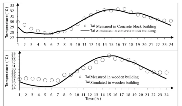
3.1.Comparison between Simulated and Measured Values of Internal Air Temperature
Many methods exist for the validation of a model: Validation with respect to a reference model like MINERVE [28] or experimental validation. We have preferred to validate our results by comparing them with experimental. So many measurements were carried out in the two types of building commonly found in the town of Douala in Cameroon.
364
Figure 5. Comparing the simulated and measured temperatures of the internal air ambience
3.2. Comparison between Wall Temperatures of Wooden and Hallow Concrete Block
The results of the simulation of the thermal behavior of the two types of buildings are presented on the figure 6.
Figure 6. Simulation of the thermal behavior of the building
On this figure, TE, TI and Trs represent respectively the evolution of temperature during a day at the level of the
external wall surface, the internal wall surface and finally the resultant dry bulb temperature in the wooden and hallow concrete block building.
- On the building constructed with hallow concrete block, the maximum temperature of the external wall is 33°C at 3 p.m and that of the internal wall is 31.4°C at 6.30 p.m. This allows a temperature depreciation of 1.6 °C with 3.5 hours as time delays between the two wall surfaces. The temperature of the internal wall surface of this building is lower than that of the external wall surface between 9.30 a.m, and 6 p.m during the day. The reverse occurs the rest of the time. The dry resultant temperature of the room varies between 27.5°C and 32°C.
Simulated in concrete block building Measured in Concrete block building
Simulated in wooden building Measured in wooden building
Concrete block building
Wooden building
T
rsT
ET
IT
rsT
ET
I365
- At the level of the wooden building, the maximum temperature of the external wall surface is 34°C at 1.30 p.m and that of the internal is also 34°C, but at 2.30 p.m. In this case, the temperature depreciation is zero and a time delay is one hour between the two wall surfaces. The temperature of the internal wall surface of the building is slightly lower than external between 07:00 a.m and 2.00 p.m, the reverse happens the rest of time. The dry resultant temperature is slightly higher than the temperatures of the wall surfaces, and varies between 24.5°C and 34.5°C. These results show that temperature depreciation and time delay obtained are different from one building to another. In the case of our study, the times delay and temperatures depreciation of the building with the walls made up of hallow concrete block are higher than the wooden building.
3.3. Model of the Thermal Inertia of the Wall
The calculation of the decrement factor and the time lag of heat wave with equations (9) and (10) for both construction materials hallow concrete block wall and wooden is summarized in the table below.
Table 4. Heat wave decrement factor and time lag through a wall for a period of 24 hours
Wall construction materials Thickness (cm) Decrement factor (%) Time lag (hour)
Wooden 3 55 1.6
Hallow concrete block 20 22 5.5
This table shows that the attenuation factor of temperature amplitude is 55%, and the time lag is 1h36min for a period of 24 hours on wooden walls. Whereas with hallow concrete block walls, the decrement factor is 22% with a time lag of 5h30min. This table shows the same trends with respect to decrement factor and the time lag, but with values higher than those in Figure 6. The values provided by wooden walls are always lower than those provided by hallow concrete block walls.
3.4. In Situ Measurements
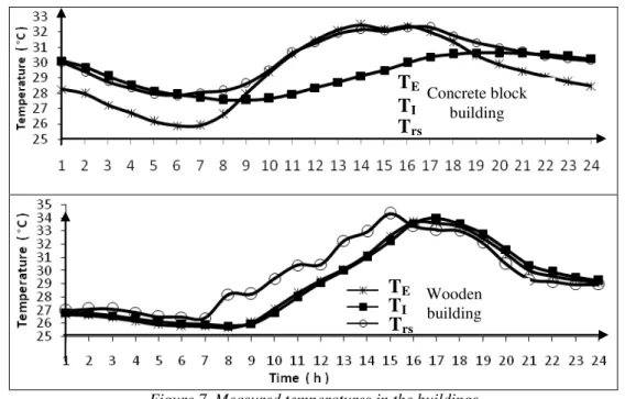
Three temperatures were measured and Figure 7 shows the results of the averages in each building over a period of 24 hours.
Figure 7. Measured temperatures in the buildings
Figure 7 above shows the evolution of the temperatures of the external wall surface TE, the internal wall surface TI
and the dry resultant temperature of internal ambience of the building TRS.
The wall built with hallow concrete block presents the its maximum temperature of 32.5°C at 2.00 p.m, while the internal wall surface temperature is 31°C at 6.15 p.m. The temperature depreciation is 1.5°C and the time lag is 4h15min between the two walls. The temperature of the internal wall surface of building is lower than that of the external wall between 08.45 a.m and 6.30 p.m during the day, and it is the reverse the rest of the period. The dry resultant temperature of the building varies between 27.8°C and 32°C.
Concrete block building
Wooden building
T
ET
rsT
IT
IT
rs366
In the wooden building, the maximum temperature of the external wall surface is 33.5°C at 4.00 p.m that of the internal wall is 34°C at 5.00 p.m. The temperature depreciation of 0.5°C and the time lag of 1hour between the two walls are recorded. The curves of temperature changes of internal and external walls are nearly identical over the entire day. These temperatures range from 25.5°C and 34°C. The dry resultant temperature of the building is higher than that of the walls between 07.00 a.m and 5.00 p.m, and reached a peak of 34.5°C at 3.00 p.m.
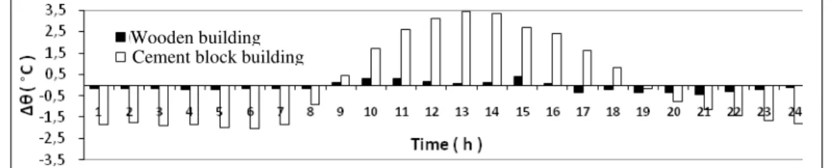
These results shows that the values of amplitude absorption and time lag between the external and internal wall surfaces of a wooden building are lower than those of a hallow concrete block building. The differences in temperature between the external and internal wall surfaces over a period of 24 hours are presented in Figure 8 below.
Figure 8. Temperature difference between the external (TE) and internal (TI) walls surface
In this figure, the smallest temperature differences between external and internal walls are recorded in the wooden building. These values varies between -0.4°C and 0.4°C. This shows that wooden building reproduces almost the external ambient temperature to the internal wall surface. The temperature difference between -2°C and 3.5°C is observed between the external and internal wall surfaces of hallow concrete block building. The difference observed has a negative or positive impact on the internal ambient air according to the outdoor ambient temperature for a wooden building particularly.
The results presented in sections 3.2, 3.3, and 3.4 show that the thermal inertia of the wall of building has an effect on the temperature of its internal wall. This parameter is related to the thermophysical properties of building materials.
It appears from this work that traditional building constructed of material as light as the wooden is best suited for households in hot and humid with a low thermal inertia, this type of building provides greater thermal comfort for hours of maximum occupancy. This moment is situated between 6.00 p.m and 6.00 a.m; otherwise, modern buildings made up of hallow concrete block store heat during the day and reject it in the building during periods of maximum occupancy, due to its high thermal inertia. Building made up of high thermal inertia materials like hallow concrete blocks, would be more useful in the construction of offices whose used is limited for the day from 6.00 a.m to 6.00 p.m. these results obtained are similar to those presented by others authors [14-19, 36]
4. CONCLUSION
The study reveals that the thermal inertia of building materials has a real impact on the temperature of the internal wall surface of building. It shows that the building constructed of material as light as the wooden is best suited for households in hot and humid climate, because with a low thermal inertia, this type of building provides greater thermal comfort for hours of maximum occupancy from 6.00 p.m to 6.00 a.m ; otherwise those with high thermal inertia such as hallow concrete block store heat during the day to be discharged into the night in the building during periods of maximum occupancy, and thus create thermal discomfort. This could be explained by the misuse of air conditioning in these types of building in order to correct the thermal discomfort. Building materials with high thermal inertia like hallow concrete blocks would be more useful in the construction of offices whose exploitation will be limited during the day in hot-humid climate.
5. REFERENCES
[1]. KEMAJOU A. Confort thermique en situation réelle et mesures d‟économie d‟énergie dans les bâtiments tertiaires
au Cameroun., thèse de doctorat, Ecole Nationale Supérieure Polytechnique de l‟Université de Douala -Cameroun, 1995, 217p
[2]. PETTANT C., Pour un nouveau modèle de production de l‟habitat en République du Cameroun. Thèse de Doctorat en Sciences de l‟Ingénieur, Génie Urbain. Ecole Nationale Supérieure Polytechnique de l‟Université de Douala-Cameroun, 1993, 250 p.
[3]. VANTROYS M., Manuel sur l‟habitat économique. Contribution au problème de la construction au Cameroun. Etude CRETP. 1973.
[4]. DREYFUS J., Le confort dans l‟habitat en pays tropical, Paris, Eyrolles, 350 p., 1960.
[5]. GIVONI B., L‟homme, l‟architecte et le climat. Paris, Editions du moniteur, 1978, 460 p. Wooden building
367
[6]. REXCOOP., Conception climatique des bâtiments en pays chauds. Séminaire REXCOOP. Paris, 1985, 139 p. [7]. Institut National de Statistique (INS) & ECAM II. Deuxième enquête Camerounaise auprès des ménages sur le
thème : Pauvreté et Santé au Cameroun en 2001. Octobre 2002.
[8]. OROSA, J. A., CARPENTE T., Thermal Inertia Effect in Old Buildings. European Journal of Scientific Research,Vol.27 No.2 (2009), pp.228-233 in http://www.eurojournals.com/ejsr.htm.
[9]. A. MOKHTARI, K. BRAHIMI et R. BENZIADA, Architecture et confort thermique dans les zones arides Application au cas de la ville de Béchar. Revue des Energies Renouvelables Vol. 11 N°2 (2008) 307 – 315 [10]. D. MEDJELEKH, S. MEDJELAKH, l‟inertie thermique du matériau et le confort hygrothermique du bâtiment.
SBEIDCO – 1st International Conference on Sustainable Built Environment Infrastructures in Developing Countries, ENSET Oran (Algeria) - October 12-14, 2009
[11]. T. CATALINA, J. VIRGONE, J. J. ROUX, E. BLANCO. Effet de l‟inertie thermique, de la surface vitrée et du
coefficient de forme sur les besoins en chauffage d‟une habitation. Congrès IBPSA, Lyon : France (2008)
[12]. O. COULIBALY., A. OUEDRAGO., J. KOULIDIATI, P. ABADIE. Etude thermique d‟un bâtiment bioclimatique
en double paroi dénommée “Newango”: Inertie thermique, confort et confort et consommation d‟énergie. 6ème
édition des Journées Scientifiques du 2iE du 4 au 8 avril 2011 au Campus 2iE Ouagadougou, Burkina Faso. 03 pages.
[13]. N. FEZZIOUI, B. DROUI, M. BENYAMINE et S. LARBI. Influence des caractéristiques dynamiques de
l‟enveloppe d‟un bâtiment sur le confort thermique au sud Algérien. Revue des Energies Renouvelables Vol. 11
N°1 (2008) 25 – 34
[14]. D. MEDJELAKH et S. ABDOU. Impact de l‟inertie thermique sur le confort hygrothermique et la consommation énergétique du bâtiment. Revue des Energies Renouvelables Vol. 11 N°3 (2008) 329 – 341
[15]. O. SIDLER. L‟inertie thermique des bâtiments: Consommation et confort d‟été en climat méditerranéen, Notes
techniques et réflexions. 2003. http://perso.club-internet.fr/sidler
[16]. B. GIVONI. Effectiveness of mass and night ventilation in lowering the indoor daytime temperatures. Part I: 1993 experimental periods. Energy and Buildings 28 ( 1998) 25-32
[17]. S. V. G. GOULART. Thermal Inertia and Natural Ventilation –Optimisation of thermal storage as a cooling technique for residential buildings in Southern Brazil., Ph.D. thesis, Architectural Association School of Architecture Graduate School in Brazil, October 2004, 196 pages.
[18]. KÉMAJOU A et MBA L., Matériaux de construction et confort thermique en zone chaude Application au cas des régions climatiques camerounaises. Revue des Energies Renouvelables Vol. 14 N°2 (2011) 239 – 248
[19]. A. MELINGUI, M. GWANFOGBE, J. NGUOGHIA et J. MOUNKAM. Nouvelle Géographie du Cameroun 3ème.
EDICEF, 120 Pages, 1987.
[20]. A. MELINGUI, M. KUETE, J. NGUOGHIA, J. MOUNKAM et D. NOFIOLE. Nouvelle Géographie 3ème.
Nouvelle édition, EDICEF, 1993.
[21]. Rapport, „Tableaux Climatologiques Mensuels (TCM)‟, Direction Nationale de la Météorologie, Météorologie Nationale, Douala, Cameroun, 2006.
[22]. KEMAJOU A. De l‟initiation à la maîtrise de la climatisation et du conditionnement de l‟air. Edition Masseu,
Belgique, Septembre 2007, 367p [23]. Outil d‟aide, logiciel DAQFactory
[24]. SHAN K. WANG. Handbook of air conditioning and refrigeration. McGraw-Hill, second edition, 2000, 1306p [25]. SACADURA J. Initiation aux transferts thermiques. TEC edition, Paris, 2000, 439p
[26]. J. LIENHARD IV, J. LIENHARD V. A heat transfer text book. Phlogiston press, Cambrige-massachussets, 3rd
edition, 2004, 762p.
[27]. A. NEVEU. Etude d‟un code d‟évolution théorique d‟une enveloppe de bâtiment (MINERVE). Thèse de doctorat,
Juin 1984.
[28]. A. MOURTADA. Simulation du comportement thermique du bâtiment : cas du logiciel CODYBA. Atelier sur la
maitrise de l‟énergie dans les bâtiments, IEPF/Ademe/Apave –ENSP Yaoundé (Cameroun), Mai 1993
[29]. J.BRAU, G.KRAUSS, J.J ROUX. Cahier des algorithmes, mallette pédagogique. CODYBA/CETHIL, INSA DE LYON, février 1992.
[30]. Outil d‟aide, CoDyBa V6.41-Manuel Utilisateur, Nov 2004, web site : jnlog.com, CETHIL [31]. P. DAL ZOTTO et al. Mémotech génie énergétique. Casteilla, paris, 1996, 585p
[32]. ASHARAE HANDBOOK, 1993, Fundamentals, Chap.26, p.26.33-26.65, SI Edition [33]. Outil d‟aide, logiciel Matlab, version 6.1
[34]. Ch. CHAULIAGUET, P. BARATCALBAL, J.P. BATELLIER. L‟énergie solaire dans le bâtiment. EYROLLES,
201 p., 1981.
[35]. N'GUESSAN M'Gbra. Analyse des performances thermiques des constructions en climat tropical. Thèse de
![Table 2. Convection and radiation heat transfer coefficients [23]](https://thumb-eu.123doks.com/thumbv2/123dok_br/17316187.249485/5.918.108.810.106.480/table-convection-radiation-heat-transfer-coefficients.webp)