Numerical investigation on
the gas entrainment rate on
ventilated supercavity body
WuGang Yang
1,2, ZhenCai Yang
3, KaiGe Wen
1,
ZhaoHui Yang
1and YuWen Zhang
2Abstract
The supercavitation technique provides a means of significantly increasing the velocity of an underwater vehicle. This technique involves essentially the creation of stable supercavity shape. The method of artificial ventilation is most effective for generating and dominating the supercavity. This paper focuses on the numerical simulation of flow field around three-dimensional body. The method is based on the multiphase computational fluid dynamics model combined with the turbulence model and the full cavity model. The fundamental similarity parameters of ventilated supercavity flows that include cavitation number, Froude numberFr, entrainment rateCQ, and drag coefficientCxare all investigated numerically in the case of steady flow and gravity field. We discuss the following simulations results in three parts: (1) the variations of the cavitation number and the supercavity’s relative diameter with entrainment rate; (2) the drag coefficient versus the cavitation number; and (3) deformation of supercavity axis caused by gravitational effect for three different fixed three Froude numbers. In the full paper, we give the comparison results of the drag reduction ratio among numerical simulation and experiment conducted in hydrodynamic tunnel and towing tank, respectively. We summarize our discussion of gravitational effect on the axis deformation of supercavity as follows: in the case of smaller Froude number, the inclination of the cavity axis increases monotonously with increasing horizontal length and reaches its maximal value at the end of supercavity; this deformation can be almost completely negligible when the Froude number Fr is larger than 7.0. The comparisons with the experimental data in the hydrodynamic tunnel and the towing tank indicate that the present method is effective for predicting the flows around ventilated supercavity; that the numerical results is in good agreement with the experimental ones and that the maximal value of the drag reduction ratio can be expected to reach the value of 90% compared with that of the condition of non-cavitation.
Keywords
Ventilated supercavitation, multiphase, hydrodynamic, numerical simulation, drag reduction, turbulence model
Date received: 5 April 2016; accepted: 9 November 2016
Introduction
Achieving ultrahigh speed is an important issue for underwater vehicles and has preoccupied scientists worldwide for decades. Even the fastest underwater vehicle was still restricted to travel at speed around 50 knots. The main reason is that the skin friction resistance underwater is much higher than that in the air. The speeds of about 50 knots represent an import-ant barrier for high-speed vehicles. At this speed, cavi-tation typically starts to be a problem, for instance, on the foils and the propulsion system. Conventionally,
1School of Electronic and Control Engineering, Chang’an University,
Xi’an, China
2College of Marine Engineering, Northwestern Polytechnic University,
Xi’an, China
3College of Science, Chang’an University, Xi’an, China
Corresponding author:
Wugang Yang, School of Electronic and Control Engineering, Chang’an University, Xi’an 710064, China.
Email: wugangyang@chd.edu.cn
The Journal of Computational Multiphase Flows
2016, Vol. 8(4) 169–177
!The Author(s) 2016 Reprints and permissions:
sagepub.co.uk/journalsPermissions.nav DOI: 10.1177/1757482X16654021 cmf.sagepub.com
cavitation means that the pressure somewhere on the upper side (suction side) of the foil becomes equal to the vapor pressure. This is only 0.012 times the atmos-pheric pressure at about 10C. If a large part of the
suction side of the foil is cavitating, the lift is clearly reduced relative to a non-cavitating foil at the same speed.1
One promising technique to overcoming this speed limit is the use of the concept of supercavitation tech-nique. This technique means that the suction side of the foil is not wetted. Partial cavitation may also cause damage to the foil structure in terms of implosion of bubbles. In addition, ventilation may occur, for instance, as a consequence of cavitation. Ventilation means that there is a connection or an air tunnel between the air and the foil surface. Occurrence of ven-tilation can also lead to significant drop in lifting cap-acity of a foil. Supercavitating foils and propellers are used to increase the speed barrier substantially beyond 50 knots. Such foil shapes have a sharp leading edge to initiate cavitation. The supercavitation provides a means of significantly increasing the velocity of an underwater vehicle. High-speed vehicle of supercavita-tion is a fascinating topic and becomes an important issue nowadays.
For some vehicles traveling through water, it is advantageous to cover the vehicle in a supercavity for the sake of reducing the drag acting on it. The under-water vehicle traveling enveloped inside a supercavity has only small regions at the nose (cavitator) and on the afterbody in contact with water. It provides a kind of means of significantly reducing the drag for a sub-merged body, thus enabling a dramatic increase of an ultrahigh speed (above 100 m/s). Now such a noticeable technology achieves breakthrough in its application only in one or two countries in the world. A superca-vitation vehicle needs to be supplied with an artificial cavity through ventilation until it accelerates to the condition at which a natural supercavity occurs and sustains. By supplying the air/gas that is insoluble or non-dissolving in the operating liquid into the cavity, the ventilated supercavity can be maintained, even if the cavity pressure is much higher than the vapor pres-sure. The method of obtaining supercavitation by arti-ficially blowing the gas into the rarefaction zone past a body with sharp edge was proposed firstly by Epshtein and Reichardt.1 Such an artificially ventilated method has been employed frequently in hydrodynamic tunnel to investigate the mechanics, characteristics, and behav-ior of supercavitation, which is one of the complicated phenomena associated with underwater vehicles. It is possible to create and study supercavitation under sig-nificantly lower mainstream using the method. For high speed fully submerged underwater vehicles, e.g. project-iles and torpedoes, ventilated cavitation has been
proposed to realize drag reduction by injecting gas in the wake region behind a cavitator, forming a continu-ous cavity covering the object surface. With the entire body being immersed in the cavity, friction drag may be significantly reduced by over 88%.2,3
The cavity shape is a matter of scientific interest, and it is also of great importance to the designer of under-water missile or rocket. The stability of a missile may depend on whether the cavity length is sufficient to envelop its fins or rudders, and its diameter may have great influence on the straightness of its trajectory. The cavity shape depends primarily on cavitation number and its size mainly on the drag force of the so-called cavitator. However, owing to some special difficulties in the experiment conducted at hydrodynamic tunnel, it is necessary to perform numerical simulation for compen-sating the deficiency of practice. The basic similarity parameters of ventilated supercavitation flows are cavi-tation number, Froude number, entrainment rate, drag coefficient, etc. They are all simulated numerically in the present paper.
Numerical model and methodology
description
Numerical simulation of cavitating flows based on multiphase flows presents two challenges: (1) Modeling of several interdependent physical phenom-ena; and (2) Robust algorithm for handling inherently dramatic variations in fluid density due to very large ratios of liquid, vapor, and gas density, as well as com-plex geometries, often with moving parts. Kunz et al.4,5 and Singhal et al.6,7 had presented independently the cavitation model to meet such stiff requirements, with implementation of the commercial code, Fluent and CFD-ACEþ.8–10 Based on mixture multiphase model, the CFD model, the standard viscous flow (Navier-Stokes), equations for variable fluid density and Shear Stress Transport turbulence model (e.g., SST model) are solved in this paper. Two additional transport equa-tions are introduced to describe the fluid density which is a function of vapor mass fraction. The solver for these equations is the celebrated SIMPLE algorithm.11,12
Basic governing equations
The basic equations that include continuity, momen-tum conservation equations, and turbulence model are shown as follows:
Continuity equation
@m
@t þ
@ðmuiÞ
Momentum equation
@ðmuiÞ
@t þ
@ðmuiujÞ
@xi
¼ @@p
xiþ
@
@xi ðþtÞ
@ui
@xjþ
@uj
@xi
ð2Þ
SST (Menter’s Shear Stress Transport) turbulence model13
@ðmkÞ
@t þ
@ðmuikÞ
@xi ¼
Pkm!kþ
@ @xi
þkt
ð Þ@@xk
i
@ðm!Þ
@t þ
@ðmui!Þ @xi ¼
t
Pkm!2
þ@@x
i
þ!t
ð Þ@@!x
i
þ2 1ð F1Þ !2
! @k
@xi
@! @xi
ð3Þ
Where variable definition as
¼F11þð1F1Þ2F1
¼tanh4 min max
ffiffiffi
k
p
!d,
500
d2! !
, 4!2k
CDk!d2
" #
( )
F2¼tanh2 max
2pffiffiffik
!d,
500
d2! !
" #
CDk!¼max
2!2
! @k
@xi
@! @xi, 10
20
,t¼
m1k
maxð1!,F2Þ
SST closure constants:¼0:09,
1¼0:31.
And boundary and far field conditions:
U1
L 5!farfield510 U1
L,
105U2
1 ReL
5kfarfield50:1U
2
1 ReL , !wall ¼10 6
1ðd1Þ2,kwall¼0
Cavitation model
The full cavitation model developed by Singhal et al.7 assumes the working fluid to be a homogenous mixture of liquid, vapor, and non-condensable gas (NCG), i.e., all three fluids are assumed to be in both mechanical and thermal equilibrium (equal velocity and equal tem-perature) at each location in the calculation domain. The convection and diffusion equations of the cavita-tion model are employed to depict the fluid density. Here, the mixed fluid density is a function of vapor mass fractionfv, which is computed by solving a
trans-port equation coupled with the mass and momentum conservation equations
1
m¼ fv vþ
fg, g g þ
flþfg,l
l ð
4Þ
A convection-diffusion equation governs the vapor mass fraction,fv, given by
@ðmfvÞ
@t þ r mV~fv
¼ r ðCrfvÞ þReRc ð5Þ
where *v is velocity vector, andCis effective exchange
coefficient.Re,Rcare phase change rates for vapor
gen-eration process (evaporation) and vapor re-absorption (condensation), the rate expressions were derived from the Rayleigh-Plesset equations and limited bubble size considerations. l, v, g are density of liquid, vapor,
and NCG, respectively.fl, fv, fg are Mass fractions of
the liquid, vapor, and NCG. In the present study, we split the NCG mass fractionfg into two components:
fg¼fg,gþfg,l. Andfg,gandfg,lrepresent the mass
frac-tions of NCG in free (or gaseous) state and in dissolved liquid state, respectively. It follows from mass conser-vation that the sum of vapor, liquid, and NCG mass fractions should be unity, i.e.,flþfvþfg,lþfg,g¼1.
The densitiesvandlare functions of saturation
pres-sure and temperature, which are constant for isothermal flows. The density of NCGgis calculated as a function
of local pressure, by using the ideal gas law, i.e.,
g¼WP=ðRTÞ ð6Þ
whereWdenotes molecular weight of NCG.
Then, volume fraction of NCG and liquid will be
g¼fgm=g, l¼1vg ð7Þ
The NCG mass fraction can be split into two com-ponents, gaseous state and dissolved liquid state. Accordingly, two more convection-diffusion equations are introduced for describing their phases: one for NCG in gaseous phase,fg,g, and another for NCG in
dissolved liquid phase,fg.l(note that the mass fraction
of the liquid itself is simplyfl).
@fg,g
@t þ r ~Vfg,g
¼ r g,grfg,g
þRdRa
@fg,l
@t þ r ~Vfg,l
¼ r g,lrfg,l
þRaRd
ð8Þ
whereRdis rate of desorption (or evolution) from dis-solved liquid state to gaseous free state. Rais rate of absorption (or dissolution) from gaseous free state to dissolved liquid state.
pressure for NCG in dissolved state, and the local mass fraction of NCG. The corresponding expressions are
Rd ¼Cdg PequilPg
1fg,g
fg,l
Ra ¼Cag PgPequil fg,l, limfg,lfg,g ð
9Þ
where Cd and Ca are empirical coefficients about 2.0 and 0.1, respectively; Pgis the partial pressure of the NCG in gaseous phase; Pequil is the equilibrium pres-sure for the NCG, andfg,l.limis the maximum solubility
of the NCG in liquid.
Grid generation and boundary condition
For the purpose of comparing with the results of experiment, a miniature experiment model which has been used in hydrodynamic tunnel is selected as
computational model in this paper. It is a slender body with a disk cavitator whose diameter is Dn. The
length of the whole computational model isLand the maximal cylindrical diameter D. Tri-ventilated hole is located in the downstream from the cavitator. The spe-cified shear wall boundary condition is used which denotes the tunnel. The main boundary conditions of the model are shown in Figure 1. Trivial distorted scale in Figure 1(b) and (c) is modified for better display.
Results and analysis
Entrainment rate
Ventilated supercavitation flow past a disk cavitator with sharp edge is typically encountered in hydro-dynamic tunnel for investigate supercavitating flow
and has received lots of attention as an effective method to generate supercavity.
In order to reduce the drag acting on the underwater vehicle, a well-defined cavity shape must be designed carefully, and the cavity size must be large enough to accommodate the vehicle. It is well known that the cavity shape depends principally on the cavitation number which is the most important parameter for ven-tilated supercavitation.
¼p1pc
0:5v2 1
ð10Þ
wherep1 is pressure at infinity or the pressure at the depth of the cavity,pcis pressure within the cavity,v1
is mainstream velocity, andis density of water. Here, it is necessary to remark that the definition of the cavitation number in the form of equation (10) is useful for the steady cavity because the numerator,p1
-pc, is the pressure tending to close the cavity and the denominator, 0.5v1,14 is the dynamic pressure effect-ive in resisting this closure.
The main problem for the ventilated cavity flows is a problem on the gas quantity necessary for supply into the cavity to keep the supercavitation of given dimen-sion.15 There are usually essential differences between the natural and ventilated supercavity. In natural or vaporous cavitation, evaporation from the cavity wall can furnish the vapor loss from the cavity tail, but in the case of the ventilated supercavity, the artificial ven-tilation rate must be in equilibrium with the rate at which the gas is entrained away. For a vehicle with large slenderness ratio, and therefore a large supercav-ity, a small cavitation number is necessary, which nor-mally cannot be achieved by natural cavitation, where the cavity is filled with vapor, but requires the furnish of air or gas into the cavity. For the ventilated super-cavity, it is of obvious interest to know the demanded quantity of gas.
The dimensionless parameter called the entrainment rate is introduced.
CQ¼ Q Cx0v1D2n
¼ 0:066
C0:0357
x0 Re0n:07141:518
ð11Þ
whereQis volumetric gas amount at the cavity pressure
pc,Cx0is drag coefficient of the conical cavitator when
¼0, andDnis maximal section diameter of cavitator.
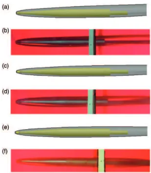
Figure 2 gives some typically numerical results of tri-dimensional ventilated cavity shape with the entrainment rate ranging from 5.6 to 6.8. Shown in trans-parent gray is a cavitation bubble shape (associated with a multiphase iso-surface that is 50% liquid and 50% gas). Qualitatively, as can be seen from Figure 2, the cavity dimension increases while increasing quantity of gas supply. This phenomenon is consistent with the results of experiments performed in hydrodynamic tunnel.
A series of experiments of ventilated supercavitation were also carried out in the high-speed hydrodynamics laboratory of Northwestern Polytechnic University in China (NWPU). Figure 3 shows the comparison of cavity shape between simulation and experiment. Evidently, the cavity has an approximately ellipsoidal shape if gravity effect is negligible. As far as the cavity shape is concerned, the computational results success-fully show the whole property of cavity, but it is not thick as compared with the results of experiment, espe-cially near the cavitator. In addition, because of gravity, the cross section of supercavity attached to the cavitator tends to rise monotonously a distance which depends on the distance downstream from the cavitator.
Figure 2. Some typical numerical results of ventilated cavity shape.
The permanent gas enters into cavity and results in the increasing of the cavity dimension and in the decreasing of the magnitude of cavitation number. When the gas concentration is sufficient, the super-cavity dimension increases considerably since the cavity can also absorb part of gas from the gas– liquid bubble multiphase flow. It is impracticable to measure cavity length directly because of the gas leakage at the wake of cavity closure and the large aspect ratio of the slender body selected, while diam-eter of supercavitation has been measured by choos-ing the phase iso-surface equal to 0.5. Based on the numerical simulation, the variation of entrainment rate along with the cavitation number, together with the cavity dimensionless diameter, were obtained as shown in Figure 4. In these cases, the cavity pressure
pcis treated as the average pressure of cavity and the relative cavity diameter with respect to the disk cavi-tator diameter Dn is treated as the reference. We can
see clearly from the Figure 4 that the cavity diameter
Dc increases monotonously with increasing the
quan-tity of gas supply.
Drag coefficient
The supercavitating drag reduction is one revolutionary technique for submerged vehicles. The most fascinating property of supercavity is that it can help us to break the conventional speed barrier, although its occurrence may cause to significant hydrodynamics attribute in the cavity flow. Underwater vehicles exploit supercavita-tion as a kind of means to reduce drag and achieve dramatically a super-high traveling speed, in this case
supercavity covers the entire length of vehicles. The drag coefficient is defined as
Cx¼ Fx
0:5v2 1Sm
ð12Þ
whereFxis the drag acting on the model (axial compo-nent) and Smis Maximal section area of the cylindrical
model (the aft part of the model).
Figure 5 gives the drag coefficient as the function of cavitation number according to the result of numerical simulation. The ventilated supercavitation regime cor-responds to small magnitude cavitation number and the friction drag coefficient is significantly lower than the pressure drag one. The reason for this is that the super-cavity occurs as if the diameter of underwater vehicle increases and as if the vehicle completely travels in air. Figure 6 gives the measured results of the experi-ments performed in the high-speed hydrodynamic tunnel and in the towing tank, respectively. The com-parison result between the numerical simulation and the experiment is shown in Table 1. The percent of drag reduction is calculated by the ratio of the differ-ence between cavitating condition and fully wetted con-dition. The numerical result is in reasonable agreement with the experiments.
Effects of gravity
Each of the three references16–18 provides some useful information for hydrodynamic design of underwater supercavitating high-speed vehicle. In this part, we draw on information provided by literature16–18 and present comprehensively numerical and experimental results of such design. In order to check the validity of our proposed design, we planned carefully water tunnel model experiments and carried them out in NWPU high-speed water tunnel. One point we wish to emphasize is that we paid special attention to the generation of non-symmetrical supercavitating zone to satisfy the balance and stability of underwater super-cavitating high-speed vehicle. Photographs of cavity
Figure 4. Computational results of entrainment rate.
flow pattern of vehicle and hydrodynamic curves obtained in the experiments indicate preliminarily that our proposed design principles and methods are feasible.
Supercavity generated in flows past the submerged obstacle is normally in the gravity field that affects the cavity flow and distorts it. For the case of artificial supercavitation, which can be easily obtained at small magnitude of the mainstream velocity when the cavita-tion number holds the same value as the case of the natural supercavity, the gravity effects are considerably important. It causes deformation of the cavity shape, i.e., the moving-upward of the ventilated cavity tail.16
Qualitatively, the distortion is due to the greater rise of the bottom than of the top of the cavity near its downstream end. The ideal ellipsoid of the cavity shape is unrealistic. The reason for this is that if the cavity has such an ideal ellipsoid shape just like the rigid body, the flow distribution would be the same as the flow about that rigid body. However, this assump-tion is inconsistent with the requirement of uniform total pressure about the cavity. Since the pressure within a steady cavity is almost uniform, the water must exert a uniform pressure on it. According to the Bernoulli theorem, the flow speed increases with depth. Hence, the local pressure must equilibrate the hydro-static pressure, which is caused by the submergence depth. Consequently, the cavity is distorted to provide proper velocity distribution in the gravity field. The steady supercavity is fixed at the end where it is gener-ated and the buoyant force causes its downstream por-tion to float upward until the newly steady posipor-tion is reached where the net buoyant force vanishes, i.e., the undistorted cavity suffers buoyant force, but the dis-torted steady cavity does not.
The Froude number is introduced to depict the deformation.
FrL¼v1= ffiffiffiffiffiffi
gL
p
ð13Þ
wheregis the acceleration of gravity andLis represen-tative linear dimension. The total length of the model is selected in this paper.
Figure 7 depicts the results of ventilated cavities at small cavitation numbers and the different Froude number ranged from 2.82 to 4.23. The relative cavity deformation is calculated with respect to the whole model lengthLselected as the reference.
It is usual to relate the change of deformation along cavity length to the square of the Froude number. The approximate formula of cavity axis slope caused by the gravity effect was investigated with the perturb-ation method by Savchenko and Semenenko17 and Savchenko et al.18who explained that the cavity axis bend increases according to the quadratic law.
Table 1. Maximal drag coefficient results of experiment and numerical simulation.
Item
Numerical simulation (present study)
Experiment in hydrodynamic tunnel (NWPU, 2012)
Experiment in towing tank (NWPU, 2011)
Fully wetted,Cx 0.2675 0.3198 0.2690
Partial cavitation,Cx 0.0323 0.0625 0.039
(¼0.023) (¼0.08) (¼0.032)
Ratio of drag reduction 88% 80% 85%
A schematic of cavity ordinate distortion in the gravi-tational field is shown in Figure 8.
Figure 9 gives the numerical results of the deform-ation in the case of different Froude number. Obviously, the float upwards of the cavity rear increases monotonously along the whole supercavity horizontal length and reaches its maximal value at the end of cavity. The smaller Froude number appears to correspond to a larger deformation. Qualitatively, the simulated results are in reasonable agreement with the experiment performed in the high-speed hydrodynamic tunnel of NWPU.
Since the gas leakage at the wake of cavity closure and calculated tolerance of interface between liquid and gas in the commercial code, it is difficult to calculate the axis inclination of supercavity. The selection of differ-ent iso-surface of the phase may result in a little warp in the magnitude of axis deformation. Here, we select 0.5 as the phase iso-surface. Theoretically, the deformation should become very small at high speed (strictly at high
values of Froude number), and this has verified by the experiments in the hydrodynamic tunnel.
Figure 10 shows the experimental result of model equipped with four fins placed symmetrically along the girth of the model near the tail. The four fins help in counteracting moments produced by cavitator and also provide lift to balance the weight and the buoyancy force. It can be seen that there is a small dependence of cavity deformation on Fr. The numerical results indi-cate that the gravitational effect should disappear almost completely for the Froude number Fr>7.0, where Fr is based on the model length. The configur-ation of supercavity then can be regarded as an approximately ellipsoid. However, since the non-symmetry of supercavity is attached to the model, add-itional equipment and angle of attack must be devised carefully for balancing the longitudinal forces of under-water vehicle. We should note that there must be some discrepancy in both captured cavitation interface and measured deformation hg. So, we must consider our
analysis approximately from this point of view. Discrepancy is observed in the transition region due to the unstable gas leakage in this stage. For realistic incident measure amplitudes, the unavoidable discrep-ancy will be so large that measurement accuracy matters.
Conclusions
The structural characteristics of ventilated cavity flow are numerically simulated based on the multiphase flow model. The basic similarity parameters of ventilated
Figure 7. Comparison of results between numerical and experiment of ventilated cavity in gravity field. (a) Computational result (FrL¼2.8); (b) experiment result (FrL¼2.8); (c) computa-tional result (FrL¼3.4); (d) experiment result (FrL¼3.4); (e) computational result (FrL¼4.2); (f) experiment result (FrL¼4.2).
Figure 9. Relative deformation of cavity axis in gravity field.
Figure 8. Schematic of gravitational effect on cavity shape.
supercavitating flows are investigated numerically and analysed in much detail. They determine the behavior of cavity flows for a given model. The simulation results show that the cavity number decreases and the dimen-sion of elliptical supercavity increase with increasing of gas supply rate. In addition, the dependence of drag coefficient on the cavitation number are investigated numerically under the condition of small cavitation number; the gravity effect which results in cavity axis deformation is calculated and studied. When the Froude number is very high, the effect of gravity can be neglected. The corresponding results of drag meas-urements under various hydrodynamic flow conditions in a hydrodynamic tunnel and a towing tank were pre-sented. The results show the promising behavior of supercavitation technique that can substantially reduce hydrodynamic drag, i.e., the value of the drag reduction ratio can up to 90% compared with that of the non-cavitation condition. The friction resistance is considerably lower than the pressure resistance when supercavity occurs. It is possible to envision and design an optimal model system with a series of match-ing favorable parameters that improve underwater vehicle’s hydrodynamics, guidance, and control per-formance for experiment or practical application. The results can be research guidance for further high-speed underwater vehicles.
Declaration of conflicting interests
The author(s) declared no potential conflicts of interest with respect to the research, authorship, and/or publication of this article.
Funding
The author(s) disclosed receipt of the following financial sup-port for the research, authorship, and/or publication of this article: The financial support provided by the National
Defense Basic Research Foundation of China
(K1804061802) and by the Special Fund for Basic Scientific Research of Central Colleges, Chang’an University (CHD2012JC074) is gratefully acknowledged.
References
1. Logvinovich GV.Hydrodynamics of flows with free bound-aries. Australia: Halsted Press, 1973.
2. Wugang Y, Zhencai Y, et al. Determination of entrain-ment rate for supercavitation vehicle.Chin J Theor Appl Mech2012; 44: 694–700.
3. Ceccio SL. Friction drag reduction of external flows with bubble and gas injection.Annu Rev Fluid Mech2010; 42: 183–203.
4. Kunz RF, Boger DA, Stineberg DR, et al. A precondi-tioned Navier-Stokes method for two phase flows with application to cavitation predication. Comput Fluids
2000; 29: 849–875.
5. Kunz RF, Boger DA, Chyczewski TS, et al.Multiphase CFD analysis of natural and ventilated cavitation about submerged bodies. ASME paper FEDSM99-7364,
Proceedings of 3rd ASME/JSME Joint Fluids
Engineering Conference, California, 1999.
6. Singhal AK, Athavale MM, Li HY, et al. Mathematical basis and validation of the full cavitation model.ASME J Fluids Eng2002; 124: 617–624.
7. Singhal AK, Athavale MM and Yang HQ. Recent advances (ventilated cavitation) with the full cavitation model. In: European Congress on Computational Methods in Applied Sciences and Engineering, ECCOMAS, Irakleion, Greece, 5–10 May, 2004. 8. Versteeg H and Malalasekera W.An introduction to
com-putational fluid dynamics: the finite volume method, 2nd ed. Essex, UK: Pearson Education Limited, 2007. 9. CFD-ACEþUsers Manual, CFDRC, 2003. 10. Ansys. CFX-11 User Manual. ANSYS CFX, 2007. 11. Patanker SV and Spalding DB. A calculation procedure
for heat, mass and momentum in three dimensional para-bolic flows. Int J Heat Mass Transfer 1972; 15: 1787–1806.
12. Tao W.Multiscale simulation of heat transfer and fluid flow problems: methods and applications. Beijing: Science Press, 2009.
13. Menter FR. Two-equation eddy-viscosity turbulence models for engineering applications. AIAA J 1994; 32: 1598–1605.
14. Rechardt H.The laws of cavitation bubbles at axially sym-metrical bodies in a flow. Great Britain: Ministry of Aircraft Production, Reports and Translations, 1946, p.766.
15. Semenenko VN. Artificial supercavitation, physics and calculation. RTO AVT lecture series on supercavitating flows. Brussels, Belgium: Von Karman Institute, 2001, pp.206–237.
16. Jean-pierre F and Jean-marie M. Fundamentals of cavi-tation, fluid mechanics and its applications. In: Madylam RM (ed.) Volume 76, New York, Boston, Dordrecht: Kluwer Academic Publishers, 2005, pp.210–214. 17. Savchenko YN and Semenenko VN. The gas absorption
into supercavity from liquid gas bubble mixture. In:Proc, 3rd International Symposium on Cavitation, Volume 12, Grenoble, France, 1998, pp.49–53.