3D MODELING OF THE STRASBOURG’S CATHEDRAL BASEMENTS
FOR INTERDISCIPLINARY RESEARCH AND VIRTUAL VISITS
T. Landes a, G. Kuhnle b, R. Bruna a
a Photogrammetry and Geomatics Group, ICube Laboratory UMR 7357,
INSA Strasbourg, France
(tania.landes, robin.bruna)@insa-strasbourg.fr b
National Institute for Preventive Archaeological Research (Inrap), UMR 7044 [email protected]
KEY WORDS: Recording, cathedral, 3D modeling, laser scanning, texturing, phased model, archaeology, virtual visit.
ABSTRACT:
On the occasion of the millennium celebration of Strasbourg Cathedral, a transdisciplinary research group composed of archaeologists, surveyors, architects, art historians and a stonemason revised the 1966-1972 excavations under the St. Lawrence’s Chapel of the Cathedral having remains of Roman and medieval masonry. The 3D modeling of the Chapel has been realized based on the combination of conventional surveying techniques for the network creation, laser scanning for the model creation and photogrammetric techniques for the texturing of a few parts. According to the requirements and the end-user of the model, the level of detail and level of accuracy have been adapted and assessed for every floor. The basement has been acquired and modeled with more details and a higher accuracy than the other parts. Thanks to this modeling work, archaeologists can confront their assumptions to those of other disciplines by simulating constructions of other worship edifices on the massive stones composing the basement. The virtual reconstructions provided evidence in support of these assumptions and served for communication via virtual visits.
1. INTRODUCTION 1.1 Historical context
The Roman Catholic Cathedral Notre Dame of Strasbourg, France, is celebrating this year the 1000 years of its foundations. Although parts of the edifice are still in Romanesque architecture, the cathedral is considered to be among the finest examples of Gothic architecture. It was classified as a FrenchHistorical Monument in 1862. The area where the cathedral is located was used in the past for several successive religious buildings. In 1015, the bishop Werner started the construction of a cathedral on the ruins of a previous one (supposed Carolingian basilica). This cathedral, built in Ottonian architectural style and also called Werner’s Cathedral, has been destroyed by fire in 1176. The only visible foundations of the Ottonian Cathedral are now under the St. Lawrence’s Chapel of the Strasbourg’s Cathedral. This basement space of about 17 m by 10 m has been investigated by several architects and archaeologists, who conducted excavations to a depth of 5 m in the years 1966-1972. It holds masonry and brick residues that are particularly interesting for the understanding of the development and history of this important urban area. Unfortunately, the basement of the St. Lawrence’s Chapel, including the foundations of the first known cathedral (Werner’s Cathedral of 1015) which serves always for the current Gothic Cathedral, is not - and will probably never be - accessible to the general public. This drawback led us to consider the possibility to produce virtual visits allowing to everybody to admire the 1000 years old foundation walls.
1.2 Multidisciplinary team
The presence of a Roman legionary camp, built at the end of the 1st century AD by the Legio VIII Augusta who occupied it until the 4th century AD, in the heart of the city of Strasbourg leads the INRAP (National Institute for Preventive Archaeological
Research) to carry out excavations in the surroundings of the Cathedral Notre Dame. The review of the Roman and medieval remains of the basement of the St. Lawrence’s Chapel became the aim of a collective research project, supported by a multidisciplinary team that includes archaeologists, surveyors, architects and art historians.
The need to georeference the main parts of the basement of the St. Lawrence’s Chapel added to the requirement of virtual visits led the surveyors proposing 3D models of the parts of interest. The 3D models to produce have therefore two aims, the first one is to support archaeological analysis and second one is to facilitate communication. That is why, in the next section, the related works will cover both topics.
2. RELATED WORKS 2.1 Data related cultural heritage modelling
The topic of 3D modeling of cultural heritage sites is largely described in the literature, in the field of photogrammetry, or more generally in the field of surveying, as well as in the computer science field. The precision of 3D models is determined by the type and quality of the data on which the process is based.
More particularly in the archaeological field, existing data coming from archives are precious and might constitute a basis for 3D modeling. For instance, LoTurco and Sanna (2009) created a 3D model of a church using 2D drawings of the facades and digital images assembled together in a 3D environment. Obviously, the final accuracy of the 3D models deduced from 2D (sometimes old) maps might not reach that of a 3D survey with 3D representations aim, but it provides a quite useful rough representation of the monument at the date of the excavation.
Laser scanning and photogrammetric techniques belong to the most widespread and appreciated techniques for 3D representation of historical monuments (Grussenmeyer and Hanke, 2010; Fiorillo et al., 2013). Despite the time consuming processing chains and the amount of data related to them, several reasons explain their success, especially the fast acquisition, the realistic rendering and more importantly, the guaranteed accuracy of the final model (Boehler and Marbs, 2004).
A determinant issue to define before starting a survey is the level of details required for the project. Agugiaro et al. (2011) performed the 3D modelling of a Maya archaeological site with four levels of details (LoD), going from the rough geometrical shape extruded in 3D from 2D maps (LoD 1) to details like ornaments from laser scanner data. By adding a database to the model, attributes can be assigned to the elements composing the model.
Among the techniques mentioned in this section, the most appropriate in our project is the laser scanning one. Photogrammetric techniques have been excluded for the modeling part, because several areas in the St. Lawrence’s Chapel are dark and very narrow. However they were useful for texturing purposes. Conventional surveying techniques are kept for the establishment of the reference network and for assessment purposes. Regarding the level of details, it will be adapted to the requirements, which are different given the floors of the Chapel.
Finally, the assignment of attributes to the model will be considered in a last step, during the creation of a phased model.
2.2 3D models visualisation and communication
In order to communicate about the excavations carried out and about the space located under the cathedral, the most appropriate solution must be chosen. Unfortunately, the possibility to easily navigate in huge 3D models remains a problem. Despite the constant evolution and progress of hardware technologies, the model sizes, especially when the models are textured with high resolution images, limit the possibilities of interactive and real-time visualization of the 3D results (Remondino and Rizzi, 2010). Therefore, the visualization or communication of models to the general public is generally determined by the available platforms hosting it (computer terminal, TV, web site, poster, flyers).
Since the point cloud obtained by laser scanning acquisitions is already a 3D model with a lot of geometric information, more and more algorithms are developed and some of them proposed for free, like for instance CloudCompare (EDF R&D), FugroViewer (Fugro), 3DReshaper Viewer (Technodigit), Lasview (LAStools). The EDL implemented in CloudCompare is particularly appreciated for the rendering of dense point clouds (Boucheny, 2009). Also mesh models might be displayed in some of these viewers. However, these free viewers are more meaningful for the transmission of data to the contractors than for the general public use, because of the data amount to be managed.
Among the free easy-to-use tools for visualizing mesh models, the PDF3D format is rather useful when 3D models must be transferred to people who are not equipped with 3D modeling software or do not want to become familiar with.
For the purpose of visualization and communication of 3D models, several large-scale projects deserve to be mentioned, like for instance Paris in 3D (http://paris.3ds.com/Patrimoine), realized by Dassault System Group. 3D simulation enables to
emphasize the temporal evolution of the site or the object under study or to simulate the future.
Augmented reality is also an interesting solution for evolving in 3D environments. It consists in the superimposition, in real time, of a virtual image on real elements. The visitors play an active role during their visit. Despite its even high cost, augmented reality will probably become widespread in the future, especially for the fun and educational support it provides.
Finally, a very concrete solution for improving communication around 3D models of sites or object is to produce physical models like for instance 3D printings.
Among all these solutions, despite its lack of interactivity, a cost-effective solution for the purpose of visualization of huge amount of data is the creation of video animations. It is adapted and cost-effective for the visualization of mesh –sometimes completed by texture- models, through a guided camera path. Therefore very specific videos with appropriate comments will be produced.
Once the level of detail and the type of required models are defined, the field campaign can be described.
3. DATA ACQUISITION
The first mission aiming to do the survey of the site consisted in the creation of an accurate control network.
3.1 Surveying
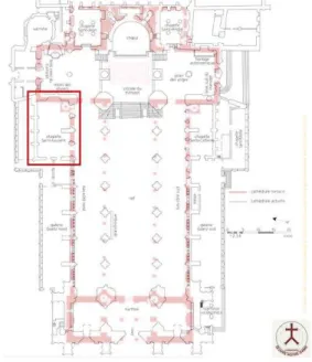
The St. Lawrence’s Chapel is located in the North part of the Strasbourg’s Cathedral (Figure 1). Since the whole Chapel is under study, the three main floors of the edifice, i.e. the basement, the ground floor and the floor under the rafters have been linked through a homogeneous and accurate network of 13 control points. Three connected traverse networks by forced centring and several controls allowed to reach better than 1 cm accuracy for all points composing the reference network (Figure 2).
Figure 1. Location of the St. Lawrence’s Chapel (red frame) in the Strasbourg’s Cathedral.
Figure 2. Exemple of a traverse network established around the roof of the Chapel and connected to the ground floor traverse.
3.2 Laser scanning
After establishment of a surveying network, a dense point cloud covering every floor of the St. Lawrence’s Chapel has been acquired in several steps. For this purpose, a phase-shift laser scanner has been used (FARO Focus 3D X 330). Its weight and compactness were particularly appreciated given the configuration of the spaces (narrow spaces, several incommodious survey stations under low ceilings).
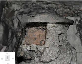
One drawback of the scanner we used is that it does not enable direct georeferencing. Therefore, an adapted positioning of spherical targets (Figure 3) as well as sufficient overlapping between point clouds were required for accurate registration.
Figure 3. Network of spherical targets established in the basement of the Chapel.
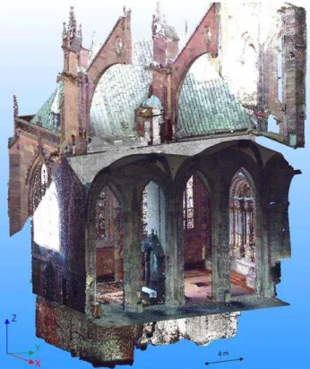
Considering the 33 laser scanning stations, a mean distance error of 2 mm has been obtained for registration accuracy. For the purpose of georeferencing the point clouds, the survey stations created previously were used for observing the centre of the targets by total station. Given the crucial importance of the basement area, this floor has been recorded with a very high point density (about 1 point every 6 mm at 10 m range). A total of 33 laser scanning acquisition stations have been defined. The whole point cloud, before resampling, was composed of 1360 million points (14 million after resampling). Thanks to the scanner integrated optical camera, RGB color-coded point clouds could be produced. Figure 4 presents the final
georeferenced and colorized point cloud of the whole St. Lawrence’s Chapel, from the basement to the roofs.
Figure 4. Colorized point cloud of the whole St. Lawrence’s Chapel (seen from the interior of the cathedral).
As mentioned in section 2.2, the point cloud constitutes in itself an interesting 3D product at least for visualization and communication. For archeological analysis however, or extraction of sectional views, a previous modeling is necessary.
4. MODELING PROCESS
The main archeological work was focused on the basement floor, that’s why the highest level of details was kept for that area. A light resampling of 1 point every 5 mm has been chosen for reducing the point cloud volume. The ground floor, the space between vaults and floor under rafters, as well as the outdoor area around the roof did require neither high density, nor very high accuracy. Therefore the resampling for the point cloud of that area has been brought to 2 cm between successive points.
4.1 Adapted modelling approaches
The most appropriate strategy for reconstructing a building depends on several factors related mainly to the reconstruction objectives and to the complexity of the objects it is composed of. Regarding the whole Chapel, from basement to the roofs, two approaches have been experimented. A first model based on geometric primitives has been generated. Some parts of the first floor and the roofs have been geometrically reconstructed by point cloud adjustment, while other have been modeled by geometry creation or extrusion, i.e. by propagation of a drawn base shape along a previously defined path. This modeling approach is interesting for saving disk space, but it implies also a certain level of simplification (Figure 5a). Only regular shapes (stairs, walls, pillars) might be faithfully described in this way. The International Archives of the Photogrammetry, Remote Sensing and Spatial Information Sciences, Volume XL-5/W7, 2015
For these reasons, this approach is appreciated for purposes of visualization, simulation and communication.
A second approach based on the meshing of the point cloud has been considered also. It enables to keep more details (statues, ornaments, gargoyles) and to describe more complex geometries (vaults) as shown in Figure 5b. This approach is ideal for modeling the basement area in order to preserve a high level of details and to guarantee a high precision. Obviously, the main drawback is the huge amount of data implied by this solution.
Finally, considering the Chapel as a whole, a combination of both modeling approaches has been suggested. This solution allowed to produce a so-called “hybrid” model, as shown in Figure 6.
(a) (b)
Figure 5. 3D model of the first floor and the roofs: a) based on geometric primitives adjustment; b) based on a meshing process.
Figure 6. Combination of geometric primitives and meshed parts for the final 3D model of the Chapel.
4.2 Focus on the 3D model of the basement
Unlike the ground floor and the roofs where a basic rendering is sufficient, the mesh model of the basement has been textured with previously corrected photographs. In order to minimize the distortions, photos were taken as much as possible normal to the surface. A photo-realistic 3D product could therefore be carried out (Figure 7).
At the same time, several orthophotos have been produced from this model. An example is presented in Figure 8. This kind of map is very appreciated from archaeologists as a support for their analysis in the field.
Figure 7. Basement of the Chapel: 3D mesh and textured model foundations under and outside the Nord side aisle of the cathedral, with the “1015 wall” on the right (red arrow).
Figure 8. Example of a longitudinal sectional view extracted from the textured 3D model.
The 3D model of the current state of the Chapel, produced through the project, was also precious for completing the 3D model of the whole cathedral, which has been constructed about 15 years ago from archived maps (collaboration Inventive Studio / Oeuvre Notre Dame). With help of this complete model and simulations based on it, several assumptions could be made by the archaeologists, who shaded new light on the history of this holy place. Indeed, a late antique basin surrounded by a massive late antique (4th/5th century) masonry wall has been discovered, although only a part of it is preserved (2.30 × 2 m). Figure 9 presents the basin as modeled and textured in the final 3D model.
Figure 9. Focus on the 3D textured model showing the part of the late antique basin discovered during the excavations The International Archives of the Photogrammetry, Remote Sensing and Spatial Information Sciences, Volume XL-5/W7, 2015
The comparison with many of the several hundred known baptisteries of the early Christian world speaks for the identification of the basin as baptismal font. Should this hypothesis be confirmed, the question of the location of the first Christian place of worship in Strasbourg would be finally answered after a long time (Kuhnle and Ristow, 2015).
In order to assess the quality of the 3D model realized for the whole Chapel, an error budget of the process covering the operations from the acquisition to the 3D model has been established in the next section.
4.3 Assessment of the 3D model of the Chapel
The main errors coming from laser scanning measurements are instrumental errors, errors coming from the object reflectivity, environmental errors and methodologic errors (Reshetyuk, 2009). The careful surveying network establishment led to 2 mm accuracy on control points. Accuracy of distance measurements has been assessed by taking measurements with a total station on a surface acquired by laser scanner. Also distances between two targets of registered clouds have been calculated in the adjusted point cloud and compared to the corresponding distances calculated with the reference coordinates of the network points. No deviation exceeds 4 mm. In this context, and since very reflective surfaces do not occur in the site, it only remains to estimate methodological errors in the error budget.
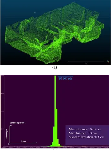
In order to assess the final 3D model of the Chapel, we carried out controls on each floor of the St. Lawrence Chapel (basement, ground floor, roof). The principle was to measure deviations between a set of points of the cloud and the 3D mesh model adjusting them. The mean error in distance is 0.05 cm, with a standard deviation of 8 mm (Figure 10). This result is very satisfying. By quadratic error transmission of the whole errors occurring in the error budget, we can estimate that the global accuracy of our model reaches 1 cm.
The same assessment approach has been applied for the ground floor and the roof. The ground floor has been modeled through combination of mesh and geometric primitives, that is why larger deviations are expected. In fact, a mean distance between model and point cloud with a standard deviation of 6 cm has been observed. It is already satisfying given the requirements. The reconstruction of the roof has been realized with geometric primitives. Therefore, the associated accuracy is expected to be worse than that of the ground floor. Indeed, mean deviations reach 6 cm for a standard deviation of 10 cm. Since ground floor and roof had to be modeled only for simulation purposes, the obtained results respect the requirements.
Between the roof and the vaults of the Chapel, a spiral staircase is visible. This staircase was condemned during the construction of the chapel and is interrupted just over the vaults. The laser scanning acquisitions allowed to determine its position and to simulate its extension to the ground floor and the masses of the basement. The geometric accuracy achieved at every 3D reconstructed floor was sufficient for that study.
Also the accuracy of the texturing process has been assessed, but only on the textured 3D model of the 1000 years old wall. An error, which is relative to the range, has been estimated to 0.5 mm at 4 m range. In summary, the geometric and radiometric quality achieved for the final 3D model largely meets the needs of the project.
(a)
(b)
Figure 10. Assessment of the mesh model of the basement floor, compared to the registered point clouds; a) color-coded point
cloud regarding the deviations: red and blue points stand for outliers, green for inliers; b) histogram of the deviations.
4.4 Phase modelling approach
Although the 3D model of the basement is geometrically exact and aesthetically satisfying, it does not fulfill the expectations of the archaeologists and historians in terms of exploitability. Obviously, as seen below, series of documents can be produced from the 3D model. For instance, using the 3D model as a background layer, a deliverable like the 2D map presented in Figure 11 helps to easily identify and highlight elements of major construction periods. But for further exploitation in 3D, our model showed some limitations.
Since the 3D model of the basement is a textured mesh, it is composed of one unique surface. But archaeologists need to consider parts of the model, which characterize areas of stratigraphic units.
This requirement implied the consideration of a specific phased modeling approach, which implies a new segmentation of the already textured 3D mesh model. Instead of building a model all at once, this approach consists in constructing the model in stages, given chronological aspects. Post-processing steps have therefore been carried out.
Mean distance : 0.05 cm Max distance : 33 cm Standard deviation : 0.8 cm
Figure 11. Map of the basement, produced from the 3D textured model of the St. Lawrence Chapel with indication of the ancient
remains (late antique basin discovered this year).
The delicate stage of post-modeling segmentation was made possible through an ongoing dialogue with archaeologists and historians, who had to integrate their assumptions into the geometric model. Some people of our team are specialists from the roman period, others from the middle age period. Their analysis allowed situating each archeological element of the basement in a specific time period. It thus seemed necessary to provide a temporal decomposition of the elements composing the model. This means that clear borders between stratigraphic units must be mapped and defined as segments in the phased model.
On the one hand, this segmentation facilitates the understanding of the basic modeling elements, and on the other hand enables the association of attributes, like time periods, to the single parts of the model. However, the decomposition involved a manual and consequently time consuming segmentation, followed in some cases by a new texturing.
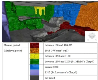
Figure 12 shows two important periods that have been put forward during this decomposition, firstly the Roman period present at the ground and the medieval period visible on walls. A colorful decomposition of the model allows to highlight the architectural evolution of the site, from a chronological point of view. Elements belonging to the same subperiod have been rendered with the same color.
Figure 12. Construction step of the 3D phased model, for a part of the basement of St. Lawrence Chapel, with regard to the
archaeological analysis.
Once the models are created and the archaeological analysis has been accomplished, the results deserve to be communicated to the general public.
5. VIRTUAL VISITS
With more than 4 million visitors a year, the Strasbourg Cathedral hosts a large number of tourists every day. Given that the excavated area in the basement of the St. Lawrence’s Chapel will not be open to public, we decided to create virtual visits based on the already created models.
Two kind of virtual visits have been proposed. The first one, dedicated to general public, shows the basement in the context of the present cathedral. In this video, a virtual camera takes us through the corridors of the cathedral as far as the St. Lawrence’s Chapel. The point cloud is used for the navigation from the attic to the ground floor (Figure 13a), whereas we switch to the textured model as soon as the camera enters the basement (Figure 13b). As mentioned in the related works section, the point cloud is a 3D model by itself and can in this way easily be exploited for visualization purposes.
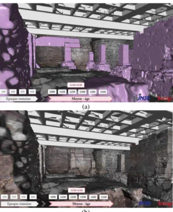
The second virtual visit is exclusively focused on the basement of the Chapel and integrates the phased model introduced above. A frieze of time leads us through the main construction periods of the various elements composing the basement of the Strasbourg Cathedral. The staging strategy is rather basic. As soon as a construction is made, the period appears in the frieze and the object is briefly highlighted in a uniform purple color before the photo-realistic texture appears (Figure 14).
(a)
(b)
Figure 13. Screenshots of a video animation dedicated to general public: a) first sequence out of the cathedral; b) sequence prior to entering the basement area.
(a)
(b)
Figure 14. Virtual visit in the phased model of the basement: a) the time period is displayed simultaneously with the corresponding archaeological elements, highlighted in purple; b) as soon as the elements have been highlighted, they take the
“real” color provided by the photo-realistic texture.
Figure 15. 3D model of the basement combined with the 3D model of the cathedral (courtesy of INSA Strasbourg &
Inventive-Studio).
As mentioned in section 4.2, the 3D model of the St. Lawrence’s Chapel produced in this project has been used to complete the 3D model of the whole cathedral, which has been constructed based on archive maps. This fusion allowed simulations and temporal restitutions of the construction steps of the previous and the current Chapel, as well as the creation of products like those presented in Figure 15.
Future video animations integrating the successive places of worship with the combination of the 3D models as background will surely enhance the communication around the evolution of this specific place, and more particularly around the late antique basin discover. It is the aim of a further project.
6. CONCLUSION
During the excavations performed in 2014 by archeologists, a late antique basin has been discovered and identified possibly as a baptismal font. This discovery was not directly dependent on the 3D model constructed in the project. However, the model was useful at different analysis levels. Firstly, it was a basis for the production of documents for working in the field. Secondly, it was precious for communication purposes, because 3D textured models and phased models facilitate the level of understanding of archeological founds for the general public. Finally and most importantly, through a multidisciplinary approach, it allowed the overlapping of assumptions and was useful as simulation support for establishing the role played over the centuries by the numerous massive stones occurring in the basement floor.
ACKNOWLEDGEMENTS
We would like to thank various people for their contribution to this project, especially J.-J. Bigot (Inrap) and C. Gaston (Inrap), S. Bengel (Fondation Œuvre Notre-Dame), S. Potier (Inventive Studio) and S. Ristow (university of Cologne) for their scientific contribution, as well as the DRAC for the authorizations and the INRAP for the financial support.
REFERENCES
Agugiaro, G., Remondino, F., Girardi, G. et Amicis, R. D., 2011. A web-based interactive tool for multi-resolution 3D models of a Maya Archaeological site. International Archives of the Photogrammetry, Remote Sensing and Spatial Information Sciences, Volume XXXVIII-5/W16, pp. 23-30.
Boehler, W., Marbs, A., 2004. 3D scanning and photogrammetry for heritage recording: a comparison. Proc. 12th International Conference on Geoinformatics - Geospatial Information Research: Bridging the Pacific and Atlantic, Universidad de Gävle, Sweden, 7-9 June 2004, pp. 291-298.
Boucheny, C., 2009. Visualisation scientifique interactive de grands volumes de données : Pour une approche perceptive. PhD Thesis, Joseph-Fourier University. http://tel.archives-ouvertes.fr/docs/00/43/84/64/PDF/these_bouchenyFINALE.pdf, 198 pages.
Fiorillo, F., Remondino F., Barba, S., Santoriello, A., De Vita, C.B., Casellato, A, 2013. 3D Digitization and mapping of heritage monuments and comparison with historical drawings", 24th Intern. CIPA Symposium, 2–6 Sept. 2013, Strasbourg, France. ISPRS Annals of Photogrammetry, Remote Sensing and Spatial Information Sciences, Volume II-5/W1, 2013, pp. 133-138.
Grussenmeyer, P., Hanke, L., 2010. Cultural Heritage Applications. Chapter in VOSSELMAN, G. & MAAS, H.G., (Eds). Airborne and Terrestrial Laser Scanning. Whittles Publishing, ISBN 978-1904445-87-6, pp. 271-290.
Kuhnle, G., Ristow S., 2015. A late antique basin in the former military camp of Strasbourg-Argentorate: part of a baptistery? In. Proc. 23. Int. Limes Congress, Ingolstadt, 2015. (to be published)
LoTurco, M., Sanna, M. (2009). Digital modelling for architectural reconstruction. The case study of the Chiesa confraternita della misericordia in Turin. Proc. of 22nd CIPA Symposium, October 11-15, 2009, Kyoto, Japan. pp. 101-106.
Remondino, F., Rizzi, A., 2010. Reality-based 3D documentation of natural and cultural heritage sites— techniques, problems, and examples. Applied Geomatics, September 2010, Volume 2, Issue 3, pp. 85-100.
Reshetyuk, Y., 2009. Terrestrial laser scanning: error sources, self-calibration and direct georeferencing. VDM publishing house Ltd, 161 pages.