Abstract—The manuscript aims to propose a new way to
accomplish the fieldbus modules control, using a flexible distributed architecture applied to the industrial Ethernet networks. The work proposal is to develop an algorithm for messages scheduling, applied to a distributed architecture, with the removal of the master controller, where only the fieldbus modules and switches operate on the network, and then having a communication messages distributed control. The proposed algorithm uses an off-line or pre-run-time type technique of messages scheduling. Therefore, the manuscript develops a new communication concept, applied industrial Ethernet networks, with communication network control and each field element distributed throughout the manufacturing process. For this, it is necessary to model the new communication concept, perform the messages scheduling (which is essential for defining the message communication order in the network trafficked, due to not using a centralized master controller) and perform verification testing and idea proposal validation.
Index Terms— Ethernet; Industrial Networks; Optimization,
Scheduling.
I. INTRODUCTION
HE PROTOCOLS network suite, known as Internet standard, is one of the most widespread communication networks architectures to interconnect computer systems. It was created by Vinton G. Cerf and Robert E. Khan [1] in the mid seventies, and has been growing since then.
The Ethernet suite protocol is the one which is now part of the Internet suite and is used in the data link and physical
Alexandre Baratella Lugli,, is Coordinator at Industrial Automation
Courses at INATEL (Telecommunication Institute) COLLEGE, MG, Brazil. (e-mail: [email protected]).
Lúcia R. H. Rodrigues Franco, is 2President at UniRede and Distance Learning Coordinator of the UFABC – Federal University of ABC/SP Brazil (e-mail: [email protected]).
layers. It was created by Robert M. Metcalfe, also in the mid seventies, to assist the physical connection of computer systems. [2, 15]
Nowadays, there are fourteen industrial Ethernet networks, as follows: PROFINET, Ethernet/IP, HSE (High Speed Ethernet), Modbus/TCP, EPA, EPL, EtherCAT, IEC 61850, JetSync, P-Net, Sercos III, SynqNet, TCnet and Vnet/IP. [3, 4, 18]
These networks operate typically with master-slave type communication. [3, 4, 5, 17]
This manuscript discusses the communication technologies, known as "industrial Ethernet". The proposal presented seeks to develop a communication methodology adequate for flexible distributed control applications. The manuscript proposal is to develop an algorithm for messages scheduling, applied to a distributed architecture with the removal of the master controller, where only the fieldbus modules and switches operate on the network, and then having a distributed control of the manufacturing process. The proposed algorithm uses an off-line or pre-run-time type technique of messages scheduling.
II. THE REQUERIMENT FOR A DISTRIBUTED CONTROL CONCEPT Most difficulties faced by distributed control system designers are related to the network elements definition and their settings, as well as checking the imposed requirements by the physical network (power cables sizing and network devices).
Currently, the main difficulty for the use of industrial networks is related to the interoperability among equipment from different manufacturers. There is a great variety of equipment, cables, connectors and other elements applied to the same industrial network. [14]
More than often, designers become dependent on a certain technology due to the lack of standardization in industrial Ethernet networks. [14]
During a project implementation, several problems may occur, but some of them are not perceived during the design
Industrial Ethernet for Distributed Control in
Factory Automation
Alexandre Baratella Lugli, Lúcia R. H. Rodrigues Franco
.____________________________________________________________________________
DOI: 10.3895/S2318-45312013000100001 ISSN: 2318-4531 phase due to the lack of adequate network simulation
resources.
Here are some facts which illustrate the problem:
A long time for starting the plant due to some type of physical network error (inadequate cable lengths or invalid electrical characteristics).
The network logical project is incorrect (for instance, the scan time is not suitable for the production process), affecting all the process dynamics.
The side effects of using the selected technology are generally not fully discussed during the network design phase and installation.
For centralized systems, the distributed system design usually does not consider master controller physical redundancy or the field modules redundancy, due to the difficulty of performing such type of analysis and the high cost to achieve this redundancy.
Another problem encountered by industrial network designers is the system control logic centralization at a single point: the network master controller. Most fieldbuses have this centralized architecture. This may cause problems to designers in the case of master controller failures, for instance, the cable rupture or power supply defaults.
Figure 1 illustrates, in practice, some of the problems mentioned above regarding a set up industrial network. The studied cases are highlighted through the use of technical reports prepared by a company in the industrial networks field, during a technical visit to a client. [6]
Figure 1. Manufacturer factory example. [6]
As a result from these technical reports, it would be useful to the network designer to have a graphical environment allowing him to verify the configured parameters and to make the required network simulations, and verifications, before starting the installation and the network devices configuration.
Furthermore, it is essential to guarantee to schedule that the control messages are adequately distributed along the field
modules and not concentrated on a single network location (master controller).
Some works carried out, [9], [11] and [21], have proposed, in some way, the solution to these problems. However, the solutions are not completely resolved from the designer viewpoint and the applicability to industrial Ethernet networks. [20] [21] The papers [20] and [21] discuss a modeling and control system for industrial Ethernet networks, with centralized control in the master controller network, not showing or mentioning the proposal for a distributed control applied to industrial Ethernet networks. Moreover, the works [11] and [19] have already proposed, in some way, using the techniques of scheduling messages applied to Foundation Fieldbus network to perform distributed control on the bus, but did not address the treatment of faults that may occur in field modules.
III. THE PROPOSED APPROACH
The fulfillment to time constraints of the scheduling system, applied to industrial Ethernet networks ensures that, when a message is transferred, it must be completed before its respective expiration time (deadline time). [10] This paradigm must be respected by the transferred messages that are related to the distributed control applications, since a non-compliance may lead to a communication failure, causing the messages loss. It is of fundamental importance to establish a precedence relation or execution order to the messages that must be transferred on the network. [10, 11] In addition, the proposed solution to distributed control, using the RM (Rate Monotonic) scheduling technique, operates with non-preemptive messages, where the messages can not be interrupted by another message being transferred. The cyclic messages (e.g. sensors reading and actuators states updating) and acyclic (e.g. a field module parameter or possible network fault) should be initiated and completed in the same execution time for deterministic guarantee and for a feasible performance on the industrial Ethernet network communication. [9, 11]
The proposed solution in this paper uses an off-line scheduling (pre-run-time technique, type RM), with previous priority in each transferred message on the bus, which is non-preemptive. With the scheduling table generated after the running scheduler a time schedule of actions is obtained to be performed on the bus through a specified prediction time defined according to the transferred messages characteristics and priorities. Therefore, it can be inserted into one or more network field modules to perform the bus communication control, to guarantee the distributed control realization applied to industrial Ethernet networks. Then, the inclusion of this scheduling table in more than one field module ensures the proposed architecture operation, even in case of failure at any field module.
The cyclical messages timing (information exchanges between sensors and actuators on the network) uses UDP, due to the imposed timing requirements by the distributed control application. [7, 8] The TCP protocol is used for acyclic messages, because the timing requirements of the transferred information are not critical in this case. [7, 8]
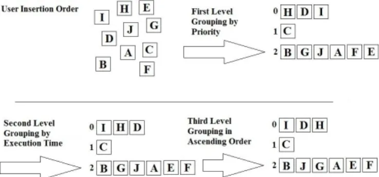
The network design approach proposed in this paper uses RM technique [9, 10], where the scheduling task is divided into three different implementation levels, according to the prioritization of the messages transferred on the bus. Therefore, the developed scheduler analyzes the set of messages that need to be transferred from each field module in three levels, to sort the information flow on the network. At the first level, the scheduler groups all messages from each field module in "sub-groups by priority", which are defined according to the message priorities (three different priority levels have been proposed: from zero up to two).
At the second level, the scheduler analyzes the total execution time of each module, in each field "sub-priority
group", creating another sub-group within the first level,
called "sub-groups by runtime" and, then arranges all the messages of each field module, according to the calculated time. In the third and final level, the scheduler combines all the messages in each "sub-group by the runtime", in ascending order.
Figure 2 illustrates the priority scheduler concept developed for the distributed control implementation approach proposed for industrial Ethernet networks.
Figure 2. Illustrating how the scheduler works with the messages.
In Figure 2, there are ten messages being transferred by the communication network among seven different field modules, where each message is represented by a letter that indicates the message is being transferred, coming from a field module to the network, as described below:
1. Square I from field module one. 2. Square B from field module two.
3. Squares H and D from field module three. 4. Squares G, A and J from field module four. 5. Square F from field module five.
6. Square E from field module six. 7. Square C from field module seven.
The traffic priorities of each message have been pre-defined through a configuration setup run at each field module. For the example of Figure 3, the timing parameters for the field modules are sent according to the logic described below:
1. The runtime field module three is less than the field module one.
2. The runtime field module four is less than the field module two.
3. The runtime field module five is less than the field module six.
4. The runtime field module which has message H is less than the field module which has message D.
5. The runtime field module which has message A is less than the field module which has message G, and this is less than the field module which has message J.
Then, as final result for the proposed approach to deal with message scheduling in Ethernet networks (RM type scheduling), there is the condition illustrated in Figure 3, where message H is the first to be transferred by the network and message E is the last one.
Figure 3. Execution order of the messages after the scheduling.
Regarding the priorities of messages to be scheduled on the bus (the first level scheduler), there is a message assignment in a fixed, non-preemptive order, as follows:
1. Transferred messages within the same field module (a field module sends the information to itself). For this case, the algorithm classifies the message priority as zero. 2. Transferred messages within different field modules (a
field module sends the information to another one, i.e. a beginning/ending type of message). For this case, the algorithm classifies the message priority as one.
3. Intermediate messages, i.e. messages that depend on previous information before sending it to another field module (a field module receives the message and forwards it to the other one). For this case, the algorithm classifies the message priority as two.
In addition, the messages transferred at the mentioned scheduling information proposal include cyclic and acyclic messages. Then, each message transferred at the proposed network will have a cyclic and acyclic time communication percentage.
Figure 4 illustrates a proposed RM scheduling, for a network containing three messages to be transferred, according to the priorities shown at the table (one, two and three, respectively).
Figure 4. Illustration for the representation of the proposed scheduling. According with the Figure 4, it is possible to perform the following tasks and timing definitions:
1. τi => Message "i" to be staggered.
2. Ci => Maximum time for message "i" implementation. 3. Ti => Actual runtime message “i”.
4. Ri => Message "i" release time or trigger.
Based on TOVAR’s work [9], it is possible to use the notation of equation 1 to represent the scheduling type RM:
τi = τi (Ti;Ci;Ri) (1)
Equation 1. RM representation.
So, the representation for the scheduling of Figure 5 is: τ1 =
τ1 (1;2;0), τ2 = τ2 (2;3;2) and τ3 = τ3 (5;6;5).
IV. RESULTS AND TESTS
In order to perform a timing analysis of the proposed distributed control system, a computational tool has been designed to validate the proposed concept.
Scenario 1: The aim of this scenario is to consider the distributed control logic and to verify some elements of the proposed network below.
DOI: 10.3895/S2318-45312013000100001 ISSN: 2318-4531 To perform the scenario validation, the under mentioned
proposed conditions must be verified:
1. Elements in the simulated network: two switches, each one with four ports, and five field modules.
2. Global parameters configured by the application designer based on their time scenario requirements: transmission rate of 10Mbps, total scan time application of 10ms, five field modules and two four-port switches. Figure 5 illustrates the network scheduling table for the proposed scenario, with five field modules, nine scheduling messages on the bus, and the distributed control among them.
Figure 5. Scheduling table to scenario 1.
The table shows the staggered communication order to the proposed scenario, according to the settings performed in each field module and the time constraints imposed by the scheduler algorithm where two of these field modules have a dual function, besides executing the control strategy. They perform simultaneously: the scheduler control of the proposed solution after previous sequence definition to be executed. The field module two performs the control, being the field module zero the reserve in the case of a failure of the main module).
The solution shows the scheduling process in each field module using the Branch-and-Bound [19] technique. The
Branch-and-Bound technique researches the best solution to a
search problem. [19] Each time message is defined as the release time minus the deadline time. The difference times between messages are below.
1. Index 0: -0,928ms. 2. Index 1: -1,4132ms. 3. Index 2: -1,1252ms. 4. Index 3: -1,3876ms. 5. Index 4: -0,8862ms. 6. Index 5: -0,4642ms. 7. Index 6: -0,3566ms. 8. Index 7: -0,3566ms. 9. Index 8: -1,3476ms.
It is possible to observe that the solution to messages scheduling in each field module is shown below.
1. Module 0: [Index 6: starts in 0ms; Index 7: starts in 0,072ms].
2. Module 1: [Index 5: starts in 0,159ms].
3. Module 2: [Index 1: starts in 0,9226ms; Index 8: starts in 0,6954ms; Index 3: starts in 0,7702ms].
4. Module 3: [Index 2: starts in 0,5816ms].
5. Module 4: [Index 0: starts in 0,4458ms; Index 4: starts in 0,3024ms].
Figure 6 analyzes the total timing consumed in this scenario, showing the total and individual timing sums, cyclic and acyclic times, from each field module.
Figure 6. Graph to scenario 1.
Scenario 2: The aim of this scenario is to validate the whole distributed control concept, and also the designed computational tool. The validation is done through a real application that serves for a comparative basis. Then, it is possible to prove that the architecture with distributed control can be applied to an industrial Ethernet network.
The experimental development was carried out with two field modules, the structure for an industrial Ethernet network, with distributed control, a switch configured with scan time of 1ms and a transmission rate of 10Mbps. The reading and writing bytes represent the temperature sensors and real actuators connected to the module and they contain six input bytes, and six output bytes for each field module.
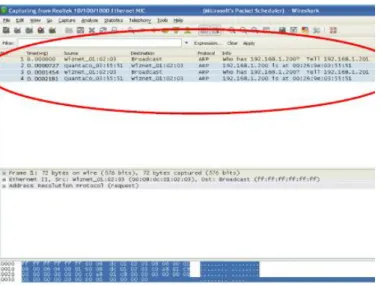
The packet communication between the two real field modules, with distributed control, can be seen in Figure 7, using a specific computational tool for capturing the messages in the Ethernet network. [16] Then, this capture tool shows the communication timing between each message, each field module, being also possible to display the total communication system timing. This timing, which is similar to the cyclic communication timing from all messages transferred on the network, is 145.4s.
Figure 7. Real field module and time analysis to scenario 2.
Figure 8 illustrates the same information listed above, but it is shown through the computational tool and the proposed architecture (developed to simulate the distributed control). It is possible to view the messages scheduling table between the two field modules and total cyclic timing graph for the field modules control strategies. The total cyclic communication timing used for this scenario is 144.4s.
Figure 8. Computational tool simulation to scenario 2.
The second scenario illustrates the cyclic scan time calculated by the developed computational tool, being 144.4s, and the cyclic scan time measured with the real application and two real field modules, being 145.4s. The real cyclic timing measurement was accomplished with the use of a network analyzer in the same network conditions proposed by the computational tool. Therefore, it is possible to conclude that the solution is in accordance with the developed modules, performing the validation of the distributed architecture.
V. CONCLUSIONS
The proposed manuscript contribution can be verified through the development of a new algorithm to perform the messages scheduling on the bus, in each field module and new temporal equations, applied to industrial Ethernet networks with distributed control, enabling greater rate and volume in the cyclic and acyclic information traffic over the network, due to its time characteristic proposed and then, solving the problems already listed above in 1.1, with the use of a centralized network. Other industrial protocols operate with
different distributed control techniques, however, due to the characteristics listed in this paragraph (speed and traffic volume), using the Ethernet standard becomes advantageous Moreover, the existence of cyclic and acyclic messages transferred in the Ethernet network is also considered, aiming to solve the problems related to centralized control. To validate the proposed approach, it was implemented a computational tool for the simulation and visualization of the presented concepts.
The results presented in this paper highlight a new concept for distributed control proposed here in, containing 5 (five) field modules and 9 (nine) different control strategies staggered on the bus. The proposed system has been modeled, being possible to show the cyclical communication time.
The paper validation was carried out by developing a computational tool for simulation and visualization of the concepts and furthermore, a real system for actual results comparison
REFERENCES
[1] CERF, V. G. and KHAN, R., E. A Protocol for Packet Network
Intercommunication. EUA, IEEE Transaction on Communication, Vol. 22,
Issue 5, 1-13p., 1974.
[2] METCALF, R. M. and BOGGS, D. R. Ethernet: Distributed Packet
Switching for Local Computer Networks. EUA, IEEE Transaction on
Communications, Vol. 19, Issue 7, 395-404p., 1976.
[3] SAUTER, T. The Three Generations of Field-Level Networks –
Evolution and Compatibility Issues. Austria, IEEE Transactions on Industrial
Electronics, Vol. 57, Issue 11, 3585-3595p., 2010.
[4] BROOKS, P. Ethernet/IP – Industrial Protocol. France, 8th IEEE
International Conference on Emerging Technologies and Factory Automation, Vol. 2, 505-514p., 2001.
[5] FELSER, M. and SAUTER T. Standardization of Industrial Ethernet –
the Next Battlefield? Sweden, 6th IEEE International Workshop on Factory
Communication Systems, 413-420p., 2004.
[6] Internet web site: SENSE Electronics Company, technical client report. Available: <www.sense.com.br>. Visited in October 2011.
[7] Ethernet/IP Specification Release 5.0, November, 2010. Ethernet/IP Normative elaborated by Open DeviceNet Vendor Association (ODVA). Available: <www.odva.org>. Visited in August 2011.
[8] LUGLI, A. B., SANTOS, M. M. D. and FRANCO, L. R. H. R. A
Computer Tool to Support in Design of Industrial Ethernet. USA, ISA
Transactions, Journal 48, 228-236p., 2009.
[9] TOVAR, E. M. M. Supporting Real-Time Communications with
Standard Factory-Floor Networks. Ph.D. Thesis, University of Porto, Porto,
Portugal, 170p., 1999.
[10] ZWEBEN, M and FOX, M. S. Intelligent Scheduling. 1st ed. Book, Morgan Kaufmann Editor, USA, 450p., 1994.
[11] HENRIQUES, A. M. Scheduling Algorithm Communication to the
Fieldbus Foundation. Master Dissertation, University of Itajubá, Itajubá,
Brazil, 87p., 2000.
[12] FELSER, M. and SAUTER, T. The Fieldbus War: History or Short
Break between Battles? Sweden, 4th IEEE International Workshop on Factory
Communication System, 73-80p., 2002.
[13] LEE, K. C., et al. Worst Case Communication Delay of Real-Time
Industrial Switched Ethernet With Multiple Levels. IEEE Transactions on
Industrial Electronics, Vol. 53, Issue 5, 1669-1676p., 2006.
[14] POPP, M. and WEBBER, C. The Rapid Way to PROFINET. 1st ed.,
DOI: 10.3895/S2318-45312013000100001 ISSN: 2318-4531 [15] HELD, G. Ethernet Networks. 2nd ed., Book, Wiley Editor, London,
England, 458p., 2000.
[16] Internet web site: Computer Analyze Tool WireShark – A Network
Protocol Analyzer. Available: <www.wireshark.org>. Visited in September
2011.
[17] LUGLI, A. B. and SANTOS, M. M. D. Industrial Networks to
Industrial Automation: AS-I, PROFIBUS e PROFINET. 1st ed., Book, Érica
Editor, São Paulo, Brazil, 176p., 2010.
[18] LUGLI, A. B. and SANTOS, M. M. D. Fieldbus Systems to Industrial
Automation: DeviceNet, CANOpen, SDS and Ethernet. 1st ed., Book, Érica
Editor, São Paulo, Brazil, 156p., 2009.
[19] FRANCO, L. R. H. R. Scheduling Messages to Fieldbus
Communication. Ph.D. Thesis, University of São Paulo, São Paulo, Brazil,
124p., 1998.
[20] ADDAD, B., et al. Analytic Calculus of Response Time in Networked
Automation Systems. France, IEEE Transactions on Automation Science and
Engineering, Vol. 7, Issue 4, 858-869p., 2010.
[21] ZHANG, L. and WANG, Z. Real-time Performance Evaluation in
Hybrid Industrial Ethernet Networks. China, 8th IEEE Proceedings of the