João Ricardo Ferreira Delgado
Licenciado em Ciências de Engenharia Eletrotécnica e de
Computadores
A SDK Improvement Towards Gesture
Support
Dissertação para obtenção do Grau de Mestre em
Engenharia Eletrotécnica e de Computadores
Orientador: Tiago Cardoso, Professor Auxiliar, FCT-UNL
Júri:
Presidente: Prof. Doutor(a) Rui Tavares Arguente: Prof. Doutor(a) Victor Santos
iii
Copyright
Kinect SDK Extension torwards gesture recognition
João Ricardo Ferreira Delgado, FCT/UNL, UNL Copyright ©.
Todos os direitos reservados.
v
“If I have seen further it is by standing on the shoulders of giants.”
vii
Agradecimentos
First of all I would like to thank my thesis advisor, Prof. Tiago Cardoso for the opportunity to contribute to this exciting field of research, and for the motivation and support given throughout this research work.
I thank the institution Universidade Nova de Lisboa for providing the conditions and materials needed for this research work. I also thank all the staff that contributed to my formation throughout my degree.
To the ones that worked before and/or with me in trying to achieve a robust and completely natural interface for the audio impaired and made this research work feel more useful than just to prove
my Master’s degree.
Quoting Sir Isaac Newton “If I have seen further it is by standing on the shoulders of giants.”, in his time he could actually name the giants in which he relied to reach further, nowadays we all contribute to this giant that is the scientific community and I thank all the individual, corporate funded or institutional research for their resilience in always reaching further, and for the sharing of knowledge which allows researches to mingle and complement each other instead of competing with themselves.
I thank all my friends for the availability to test and help throughout this thesis, for the incentive given, the out-of-the-box thinking and for all the disruptive ideas that without even making sense at first allowed for some of the implemented features.
ix
Resumo
A Interação Humano-Computador tem sido um dos principais focos da comunidade tecnológica, especialmente o campo de investigação das Interfaces Naturais visto que, desde o lançamento do Kinect Sensor para o mercado o objetivo de criar interfaces completamente naturais ficou muito mais perto de se tornar realidade. Tirando partido destas condições a presente tese propõe construir o esqueleto da mão de modo a reconhecer as formas presentes na linguagem gestual.
A solução proposta utiliza o Kinect Sensor para uma melhor segmentação da mão, algoritmos de análise de imagens para estender o esqueleto da mão através da extração de características de alto nível. De modo a reconhecer formas complexas a presente tese propõe uma redefinição do contorno da mão de modo a torna-lo imutável a operações de translação, rotação e redimensionamento bem como um conjunto de ferramentas para atingir um bom reconhecimento.
A validação da solução proposta estende o Software Development Kit do Kinect de modo a permitir ao programador aceder aos novos pontos inferidos, e cria uma plataforma baseada em template-matching que utiliza o contorno para definir a forma da mão. Este protótipo foi testado perante um conjunto pré-definido de condições tendo mostrado uma boa taxa de sucesso ao nível do reconhecimento bem como provado a sua adequação para aplicações em cenários de tempo real.
Palavras chave:
Kinect
SDK
Extension
Shape Recognition
xi
Abstract
Human-Computer Interaction have been one of the main focus of the technological community, specially the Natural User Interfaces (NUI) field of research as, since the launch of the Kinect Sensor, the goal to achieve fully natural interfaces just got a lot closer to reality. Taking advantage of this conditions the following research work proposes to compute the hand skeleton in order to recognize Sign Language Shapes.
The proposed solution uses the Kinect Sensor to achieve a good segmentation and image analysis algorithms to extend the skeleton from the extraction of high-level features. In order to recognize complex hand shapes the current research work proposes the redefinition of the hand contour making it immutable to translation, rotation and scaling operations, and a set of tools to achieve a good recognition.
The validation of the proposed solution extended the Kinects Software Development Kit to allow the developer to access the new set of inferred points and created a template-matching based platform that uses the contour to define the hand shape, this prototype was tested in a set of predefined conditions and showed to have a good success ration and has proven to be eligible for real-time scenarios.
Keywords:
Kinect
SDK
Extension
Shape Recognition
xii
Index
1. INTRODUCTION ...1
1.1 Motivation ...1
1.2 Objectives ...5
1.3 Research work Structure ...6
2. STATE OF THE ART ...7
2.1 Hand Gesture Recognition ...7
2.1.1 Vision Based Gesture Recognition ...8
2.2 Hardware Solutions ... 14
2.2.1 Kinect Overview ... 14
2.2.2 Alternative Solutions ... 16
2.2.3 Software Development Kit... 18
2.3 SDK Extensions ... 21
2.3.1 Object Oriented Programming Solutions ... 21
2.3.2 The .NET Way ... 22
2.4 Conclusion ... 24
3. PROPOSED SOLUTION ... 25
3.1 Hand Segmentation ... 26
3.2 Feature Extraction ... 27
3.3 Shape Recognition ... 30
3.4 Proposal Specification ... 33
3.5 Conclusion ... 37
4. VALIDATION ... 39
4.1 Methods and Materials ... 39
4.2 Segmentation ... 40
4.3 Skeleton Extension ... 42
4.4 Shape Recognition ... 45
4.4.1 Template Creation ... 45
4.4.2 Recognition ... 47
xiii
5.1 Conclusion ... 51
5.2 Future Work ... 52
xiv
Image Index
Figure 1.1 - Human-Computer Interaction Research, (Brad A-Myers, 1998) ... 1
Figure 1.2 – Human-Computer Interaction Paradigms ... 2
Figure 1.3 - Natural User Interfaces Paradigm ... 3
Figure 2.1 - Jumping gesture example: a) Gesture Illustration; b) Neural Network (Jana, 2012) ... 9
Figure 2.2 - Algorithmic Approaches Flowchart (Jana, 2012) ... 10
Figure 2.3 - Hand model: a) Hand Anatomy, b) Hand Model ... 11
Figure 2.4 - Key Anchor Points of the Hand (Li, 2012) ... 12
Figure 2.5 - Low-Level features representation of hand: a) hand image b) time-series curve representation (Daniela Ramírez-Giraldo, 2012) (Zhou Ren J. Y., 2011) ... 12
Figure 2.6 - Microsoft Kinect Sensor ... 14
Figure 2.7 - Kinects Joint Prediction Accuracy (Jamie Shotton) ... 16
Figure 2.8 - Other Hardware Solutions: a) Asus Xtion; b) Leap Motion ... 16
Figure 2.9 - Kinect High-Level Class Diagram ... 18
Figure 2.10 - RGB Pixel Structure ... 19
Figure 2.11 - Kinects Raw Depth Data Structure ... 19
Figure 2.12 - Kinects Tracked Joints ... 20
Figure 2.13 - Coordinate Mapper Class and Implemented Point Structures ... 20
Figure 2.14 - Car Structure Representation: a) UML; b) C# ... 21
Figure 2.15 - Containment Solution: a) UML; b) C# ... 22
Figure 2.16 - Inheritance Solution: a) UML; b) C# ... 22
Figure 2.17 - .Net Solution: a) UML; b) C# ... 23
Figure 2.18 - Solutions Implementation: a) Containment; b) Inheritance; c) Extension Methods .... 23
Figure 3.1 - Generic Shape Analysis Flow ... 25
Figure 3.2 - Eight-point Neighborhood Representation ... 28
Figure 3.3 - Convexity Defect Data Structure ... 29
Figure 3.4 - Complex Number Representation ... 31
Figure 3.5 - Use Case Scenarios: a) Skeleton Extension; b) Shape Recognition ... 33
Figure 3.6 - Overall Class Diagram ... 34
Figure 3.7 - Activity Diagram "Extend Skeleton" ... 35
Figure 3.8 - Activity Diagram "Add Template" ... 35
Figure 3.9 - Activity Diagram "Recognize Shape" ... 36
Figure 3.10 - Overall process for the proposed solution ... 37
Figure 4.1 - Kinect Operating Distance for Test Conditions ... 39
Figure 4.2 - Hand Region Segmentation: a) Original Depth Frame; b) Hand Region Depth Frame 40 Figure 4.3 - Hand Segmentation Process: a) Segmentation by Player Index; b) Depth threshold segmentation; c) Final Hand Output ... 41
xv
Figure 4.5 - Fingertip Extraction Process: a) Contour Extraction; b) Polygonal Approximation of Contour; c) Hull Extraction; d) Convexity Defects Computation ... 43
Figure 4.6 - Convexity Defects Representation ... 44 Figure 4.7 - Contour Definition: In black standard definition as the set of points, in red the vector representation ... 46
Figure 4.8 - Representation of a contour a) and its autocorrelation function b): in blue is represented the norm of each component and in red the corresponding arguments ... 46
xvii
Table Index
1
In this chapter it will be given an introduction to the motivation that lead to this research work, the objectives that were defined for the solution to be proposed and the overall structure of this research work, aiming to provide the overall frame for this thesis.
Since the dawn of computer science, Human-Computer Interaction (HCI) has been one of the
major concerns of the scientific community, striving to enhance the user’s experience regarding his
communication with a machine.
We witnessed the evolution of the mouse and of its portable counterpart, the touchpad, the refinement of voice recognition techniques and the appearance of gesture recognition algorithms which have been lately catalyzed by the availability and the improved reliability of depth cameras as well as by the consistent advancement in image analysis algorithms.
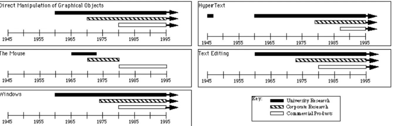
It has been clarified that “the most famous HCI successes developed by companies are deeply rooted in university research … In fact, virtually all of today’s major interface styles and applications have had significant influence from research at universities and labs, often with government funding”
(Myers, 1998), this is illustrated by the image bellow:
Figure 1.1 - Human-Computer Interaction Research, (Brad A-Myers, 1998)
The field of Human-Computer Interaction is a multidisciplinary field that is intimately connected with computer and social sciences. The goal of HCI is to create new interaction paradigms between user and machine, developing descriptive models for these interfaces and develop methods to evaluate them.
1.
Introduction
2
One of the possible definitions of HCI would be (Hewett, s.d.):
“Human-computer interaction is a discipline concerned with the design, evaluation and implementation of interactive computing systems for human use and with the study of major phenomena
surrounding them.”
Since HCI studies the behavior of both human and machine, it draws support from fields in either side:
On the machine side skills such as computer graphics, operating systems and programing languages are required;
On the human side the relevant skills are communication theory, linguistics, cognitive psychology and social sciences, among others.
Poorly designed human-computer interfaces can often lead to many unexpected problems often known as user errors. This can be mitigated if the human behavior is studied in order to predict the
user’s actions.
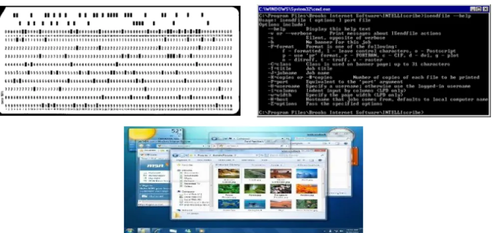
The field of HCI has gone through several important paradigm shifts that defined it’s history and evolution, from a time where the interaction between the human and the computer was reduced to perforated cards processed sequentially to an interaction with virtual objects as natural as the one with their real counterparts.
Figure 1.2 – Human-Computer Interaction Paradigms
3
The paradigm that followed was the Command Line Interface (CLI) (1960s – early 1980s) that arose with the development of the first computer monitors and keyboards. The user no longer had to punch cards, feed them to the machine and wait, instead the different users could get access to a terminal and interact directly to the computer in what resembled real-time.
This was the paradigm under which the first personal computers (PCs) came to be. The users could create, save, delete, copy or move files or directories through text based commands. This can still be used today in the Linux command line or Windows command prompt.
The third interaction paradigm is the Graphical User Interface (GUI) (1980s - 2000s), this interface enabled the user to interact with program windows, menus and buttons using the mouse to click or drag the controls in much the same way as he would with the papers on the top of his desk, hence the desktop metaphor.
This paradigm in association with the decrease of both price and size drove the computers to become a household appliance that people would use in their everyday lives.
Nowadays a new paradigm is emerging, the so called Natural User Interfaces (NUI) (since 2000s), the overall idea is that rather than the user having to rely on additional hardware as means of input, they can interact with the computer in the same way as they interact with real-life objects and people. This usually means speech, hand and body gestures, touch and facial expressions, as well as making the machine able to sort out commands in a language much more flexible than the actual computer syntax.
Figure 1.3 - Natural User Interfaces Paradigm
Natural User Interfaces (NUI) are interfaces designed and constructed in order to feel invisible to the user, and remain invisible as he learns, increasingly complex interactions.
Most computer interfaces are artificial devices that require the user to learn how to operate them. NUI aims to develop interfaces that can be controlled with the same interactions that the user uses in the real world, thus becoming Natural to him.
4
With the appearance of depth cameras fully natural interfaces are arising, Microsoft already produces games for their consoles that require the user to hold no additional hardware in order to give instructions, rather the user interacts with the environment by means of body gestures.
This interaction paradigm allows the machine to capture complex human gestures that are very human-like and reproduce them which enables the machine for applications in precision work such as surgery or exploration work.
The interaction by means of human gestures allows for more uses for interfaces instead of only
issuing commands to a machine, instead and since the input device is the user’s body, the machine
can actually evaluate the interaction providing for medical, therapeutically and educational applications this, besides opening more space for interaction to develop also attracts more research to the field.
Nowadays, the entertainment industry, motivated by the creation of more immersive content, has been at the edge of HCI research and thus were the first to commercialize this new generation of
input devices, such as Nintendo’s Wii, Sony’s Mover and Microsoft’s Kinetic, as well as Smart TV’s that
offer the user the possibility to control the TV without any auxiliary hardware as remote controls.
Regarding Microsoft’s Kinect, the scientific community quickly realized its potential for more
than just gamming and pressured Microsoft for a Software Development Kit (SDK), as this request was replied we began to see, thanks to the resourcefulness of the always resilient scientific community, lines of research in remote medical surgery and physiotherapy just to mention a few.
5
The main goal of this research work is to extend the existing Kinect SDK in order to include the
skeleton of both user’s hands, as suggested by the thesis title itself.
Since this thesis was included in the project of the creation of a gesture based input software for the audio impaired, one secondary goal is to create a gesture recognition platform for static hand gestures. Regarding movement based hand gestures please refer to (Galveia, Cardoso, & Rybarczyk, 2014).
The solutions objective can be divided in two major parts:
Creation of an algorithm that uses the joint information provided by the Kinect sensor to infer the position of new joints on both user’s hands, in real-time.
Creation of a gesture recognition platform able to recognize sign language in real-time. The implementation is to be tested and evaluated using Portuguese sign language but should be implemented as generic as possible.
The aim is to provide a set of tools to support the creation of gesture based application by offering a more complete definition of the hands, since these are the main human soundless input devices.
6
The present thesis is arranged in the chapters described below: Chapter 2: State of the Art
This chapter will give the reader an overview of the current state of the technology in the areas related to this thesis.
Chapter 3: Proposed Solution
This chapter will focus on the proposed solution, how it works, what it offers and how it was built, as well as all the background needed to understand the topics that will be discussed. Chapter 4: Validation
In this chapter the validation outputs will be presented and analyzed in order to place and evaluate the performance according to the objectives proposed above.
Chapter 5 Conclusions and further work
Finally this chapter will conclude upon the proposed solution and the prototype used for the validation and produce constructive feedback for further developments in the field.
7
This chapter will provide an overview of the state of the art that constitutes the foundations of hand gesture recognition research field as well as an analysis of the available hardware solutions and extension methodologies in order to justify the initial assumptions for this dissertation.
The primary goal of gesture recognition research is to develop a system able to identify specific human gestures and use them either to control a device or to convey information.
In light of this the direct use of the user’s hands as an input device has been a big focus of the scientific community as it presents a very attractive mean to provide a fully natural user interface.
The methods that have been developed to interpret human hand gestures may be divided in two main categories:
Electro-mechanical devices: This methods usually employ a data glove (Foxlin, 2002), a glove with optical or mechanical sensors attached that converts the flexion of the fingers into electrical signals that are used to identify the hand posture, providing the most complete definition of the posture. However, besides the fact that they are very expensive for recreational use and that they require complex calibration procedures, they also force the user to wear the glove and all the wire connecting it to the machine, hindering the naturalness of the interface.
The most recent development in electro-mechanical devices was MYO (Labs, 2013), an armband from Thalmic Labs that uses Electromyography (EMG) electrodes to detect subtle differences in the muscles electrical signals, and implements a Machine Learning algorithm to detect around 20 different hand gestures. The information is transmitted to the machine via Bluetooth eliminating the need for wires connecting the sensors to the machine.
Vision-based approaches: These approaches have been proven a viable alternative to the use of electro-mechanical devices since they are based on computer vision rather
than additional hardware on the user’s end. These have lately been catalyzed by the availability of depth sensors that obviate the impact of background and lightning conditions in the performance of the system.
2.
State of the Art
8
The focus of this dissertation will be on vision based solutions since the primary goal is to develop a gesture recognition platform that targets the audio impaired community and so the reach of the proposed solution is to be as wide as possible, meaning that as far as hardware is concerned a vision based implementation have more to offer in terms of availability. The state of the art of Vision based approaches is discussed in detail in the upcoming subsection.
2.1.1 Vision Based Gesture Recognition
Generally a hand gesture may be separated into its dynamic and static components meaning the hand movement and the hand shape.
For the dynamic component literature is divided in two main categories:
9
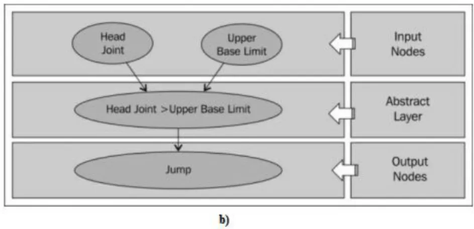
Figure 2.1 - Jumping gesture example: a) Gesture Illustration; b) Neural Network (Jana, 2012)
The main approach is the use of Hidden Markov Models (HMM) process to classify hand gestures (Xiaoyu Wu, 2012), (Youwen Wang, 2012). These statistical process treats each system being modeled as a stochastic process that satisfies the Markov property.
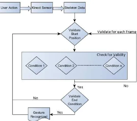
Algorithmic Approaches - define the gesture as a set of manually encoded conditions and restraints. The Algorithmic approaches are usually based on the comparison of high level features such as the position and/or orientation of joints. The approach differs according to the gesture to be recognized, some gestures are simple to be defined according to some pre-defined set of conditions or result set. By matching the performed action against the result set one can conclude whether or not the user has performed a certain gesture. For a simple gesture we need to validate three different components of the gesture:
o Start Position o Condition o End Condition
10
Figure 2.2 - Algorithmic Approaches Flowchart (Jana, 2012)
For example let us consider the Swipe to Left gesture and let’s assume that that the gesture is always done with the right hand. Defining the conditions that compose the gesture will result in a similar output as the one described below:
We say that the gesture has started (start condition) if the left hand is below the left shoulder and the right hand is below the right shoulder. As for the gesture movement, the user will move the right hand from left to right maintaining the start conditions. This condition will have to be validated for a pre-defined number of frames and must return success every time. In the end condition we validate weather or not the distance between the right and left hands has decreased in relation to the starting point.
One other example of an algorithmic approach is the one used by (Galveia, Cardoso, & Rybarczyk, 2014) which defines the dynamic component of hand gestures as a set of 3rd degree polynomial equations. This author proposes the creation of a gestures library, represented by the equations and, afterwards, the corresponding recognition, reduced to the
11
For the recognition of the static component of the hand gesture the approaches in literature can be differentiated according to the extracted features as follows:
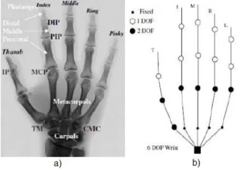
3D Reconstruction – these approaches attempt to compute a 3D model providing a complete definition of the hand (this eliminates the self-occlusion problem inherent to 2D projections). However a robust 3D reconstruction is difficult to achieve, according to. This fact is mainly based on the need for better resolution on the input mechanisms, on one hand side, and the high computational costs needed for rendering, on the other hand side. This last fact is incompatible with real-life requirements. For example in (J. Lee, 1993) the hand was defined by a 27 Degrees of Freedom (DOF) model illustrated bellow:
Figure 2.3 - Hand model: a) Hand Anatomy, b) Hand Model
This model has been used in further studies and has improved by introducing one DOF do the CMC joints (Kenichi Nirei, 1996) or by adding extra DOF on the MCP joints (Matthieu Bray, 2004).
12
Figure 2.4 - Key Anchor Points of the Hand (Li, 2012)
This approaches have been developed not only with depth cameras but with regular RGB cameras too being required, in this last case, that only the hand is seen by the camera since the segmentation will be color-based. Although color segmentation is less effective, RGB cameras have the advantage of providing a better resolution than depth cameras which will produce a better input for the image analysis algorithms and thus a more reliable output of the feature extraction process.
Low-Level Features– these approaches extract features that are fairly robust to noise and can be extracted quickly. For example (Zhou Ren J. Y., 2011) defines the hand shape as a cluster based signature in which the Y axis represents the distance of each contour point to the center of the hand shape, normalized by the radius of the maximum inscribed circle, and the X axis represents the angle each contour point and the start point make with the center point, as illustrated in figure bellow:
a)
b)
Figure 2.5 - Low-Level features representation of hand: a) hand image b) time-series curve representation (Daniela Ramírez-Giraldo, 2012) (Zhou Ren J. Y., 2011)
13
From the point of view of the processes used to recognize the static gestures’ components, the
research community proposes:
Algorithmic Approaches - based on a set of conditions and restraints between key anchor points and their orientation, much in the same way that they are used in dynamic recognition. These types of solutions are usually used by High-level features approaches since they will need to define the hand pose with a set of conditions and restraints that will be checked in the recognition process.
Template Matching Approaches - define the gesture as a signature immune to the three geometric transformations (T, S, R - Translation, Scaling, Rotation) and then match it against a shape library towards finding the best match, these recognition process is usually used in approaches where the feature extraction process provides as results in a signature of the hand pose, they usually give a better performance than the previous due to the fact that are based on a degree of similarity rather than a set of rules, providing for a better handling of false positive situations.
14
This Section strives to give the reader an understanding of the available technologies and how they work, starting by Kinect that has been the platform of choice for the work done so far and then presenting other alternatives making a critical analysis of all of them. The Section will culminate in an
analysis of the Kinect’s SDK, since this will be the chosen platform for this research work by the reasons that will become evident further in this Section.
In November 2010 Microsoft introduced Kinect to the world, originally introduced as “Project Natal”, this new gamming controller, designed in collaboration with PrimeSense, was presented as an
accessory for the Xbox 360.
In the eyes of the scientific community, the Kinect’s potential for other application areas quickly became evident, so a request was made for an official SDK to be made available. This request was replied in June 2011, it was released allowing room for the scientific community to contribute to the development of NUI related research. Furthermore, in February 2012 a windows version of Kinect was released, allowing for a near mode that was able to recognize the player at reduced distances and in a seated position.
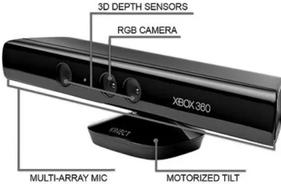
Figure 2.6 - Microsoft Kinect Sensor
The components of the Kinect sensor are shown in the image above and can be summarized as follow:
A tilt motor that enables Kinect to change its direction in both horizontal and vertical axis;
2.2
Hardware Solutions
15
A directional microphone array composed by four microphones that implement vocal commands which are processed at 16 KHz sampling rate, with a 16-bit resolution. A RGB camera with a maximum resolution of 1280x960 pixels at a frame rate of 12
frames per second (FPS) and 640x480 pixels at 30 FPS, it employs a Bayer filter. There is nothing excitingly new about it but it has proven its usefulness.
A depth camera which uses a novel method for data acquisition, it provides a 640x480 pixel resolution at 30 FPS.
Before Kinect, depth data was being obtained using a method known as Time-of-Flight (ToF), which is based on the time the light takes to cover the distance from the camera to the object in question. Rather than this, Kinect gathers depth data using speckle pattern, a field pattern generated by the interference of waves with the same frequency but different phases and amplitudes, resulting in a wave with an amplitude that varies randomly.
The Infrared (IR) projector irradiates the camera’s field-of-view with a speckle pattern, this pattern is random in order to reduce the complexity of the system and to facilitate the 3D reconstruction. The IR camera then captures the reflected pattern and reconstructs the depth map by running a parallel computer vision algorithm called “Light Coding”.
Regarding this, Adi Benson, PrimeSense’s VP Business Creation stated in (PrimeSense: Beyond Natal Article, s.d.): “PrimeSense is using proprietary technology that we call Light Coding. It’s proprietary. No other company in the world uses that.”
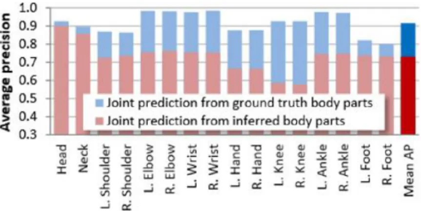
This technology has low complexity which allows real time processing with low latency. Kinect has yet another trump card, the so called Skeleton frame. The proposed system runs at 200 frames per second on consumer hardware and accurately predicts 3D positions of body joints from a single depth image, without the use of temporal information.
It works frame-by-frame across different body shapes and sizes and naturally handles self-occlusion and poses cropped by the frame. It uses a “novel intermediate body parts representation
design to spatially localize joints of interest at low computational cost and high accuracy” and randomized decision forests that “have proven fast and effective multi-class classifiers for many tasks
and can be efficiently implemented on the GPU”.
16
Figure 2.7 - Kinects Joint Prediction Accuracy (Jamie Shotton)
Despite the insight given by the previous section about the Kinect sensor and its advantages it is still profitable to get a glimpse of the alternative hardware solutions in order to safely state that Kinect is (or is not) in fact the most adequate system for this research work.
There are not many depth sensors available for the general public in the market, in fact, besides the Kinect sensor there are only two other devices that are worth mentioning: Asus Xtion and Leap Motion, both illustrated in the image below.
a) b)
Figure 2.8 - Other Hardware Solutions: a) Asus Xtion; b) Leap Motion
The Xtion sensor is produced by the Taiwanese computer hardware company Asus and it actually uses the same technology for depth data acquisition than Kinect, as both sensors are inspired on the Carmine 1.08 model from the Israeli company PrimeSense.
Asus Xtion appeared on the market slightly after Kinect and its first release did not offered a
RGB camera. Although they rectified this on the Xtion Live, Asus products still don’t offer a tilt motor,
allowing only for manual positioning.
17
Despite all the hardware discrepancies, Kinect’s joint estimation system is still the biggest advantage it has since Xtion only provides raw depth data, without inferring any information regarding the human skeleton, or any other for that matter.
Leap Motion is a slightly different piece of hardware. When it was first revealed to the general public, it brought with it the expectation of a new and unique user experience. The Leap, as it was first introduced, is a pen-like device that is designed to track only the user’s hands. It easily captivated the interest of the community due to its low price and its astonishing precision of 0.01 mm. It uses two monochromatic infrared cameras and two infrared LEDs. The LEDs generate a 3D pattern of dots of infrared light and the cameras capture the reflected data at about 300 frames per second, sending it to be analyzed by Leap Motion controller. The 3D position data is inferred by comparing the 2D frames generated by both cameras.
The device is capable of detecting all ten fingers simultaneously and its purpose is to allow users to control an application using hand gestures. It is similar to using a touchscreen device without the screen, this, allied to the fact that only Leap oriented applications support the device, meaning that for an application to support Leap Motion gestures it has to be rewritten to do so, makes this system more of an entertainment tool according to the reviews.
In the table below the specifications of the devices can be compared:
Table 2.1 - Hardware Comparison
Kinect Xtion Live Leap Motion
RGB Camera Yes Yes No
Depth Sensor Yes Yes Yes
Skeleton Tracking Yes No Hands only
Official SDK Yes No (Uses OpenNI) Yes
Dimensions (cm) 28.2 x 7.2 x 7.8 24.4 x 15.5 x 8 7.6 x 1.3 x 3.1
For the objectives referred above the Kinect Sensor proved to be the most reliable option, its advantages in relation to Xtion are evident and the joint estimation algorithm provides some interesting reference points in the body that can spare a lot of processing. As for Leap Motion it has a much better
resolution in the user’s hands but extending its SDK to include the hand’s skeleton would prove to be
18
As discussed in the previous section Kinect will be the chosen hardware platform for this research work, this section will explore the Kinect’s Software Development Kit (SDK) in order to give an understanding of the offered classes and features.
The Kinect SDK offers a number of tools for the developer, being the goal of this research work to extend it, it is divided into three different frames: color, depth and skeleton. It is up to the developer to use any one of them as well as any combination of frames. The different frames have different resolutions and frame rates that can be manually set by the developer, in the case of the skeleton frame smoothing parameters can be set for joint estimation.
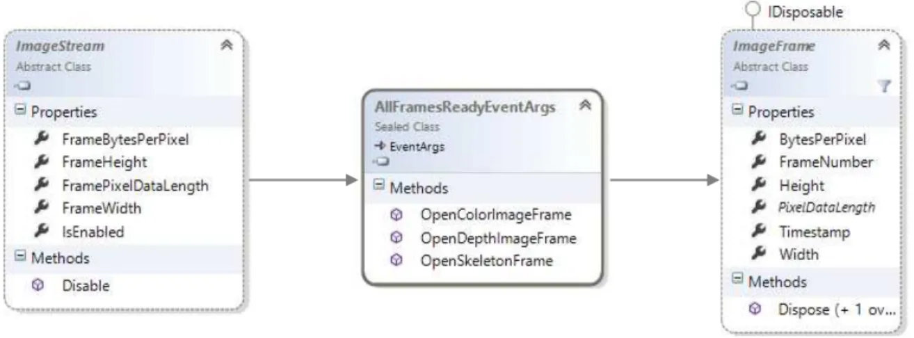
The Kinect SDK implements two top-level base classes: ImageStream and ImageFrame from which both color and depth classes derive, since the skeleton frame is constructed and not directly gathered from the cameras it has its own classes that will be analyzed further in this section. The class ImageStream represents the succession of frames sent by the device and ImageFrame represents each singular frame, every time ImageStream has a new frame it launches a FrameReady event that allows the developer to access the ImageFrame instantiation of that frame.
Figure 2.9 - Kinect High-Level Class Diagram
For each frame a “FrameReady” event is offered as well as an “AllFramesReady” event that
automatically synchronizes the frames and is triggered as soon as all of the frames are ready to be processed.
Each RGB pixel of color frame is an array of size four as illustrated below:
19
Figure 2.10 - RGB Pixel Structure
Kinect supports different formats for color image: RGB, YUV, Bayer and even an infrared mode using the IR emitter of the depth camera. ImageFrame implements a BytesPerPixel which makes easier to calculate the stride for each different format.
For depth data purposes the Kinect SDK provides a DepthImageStream and a DepthImageFrame classes that define the properties and methods to handle raw depth information. Raw depth data is provided as a 16-bit array, where the first three bits represent the player index and the remaining bits the distance of the pixel to the sensor, in mm as illustrated in figure 2.8.
Figure 2.11 - Kinects Raw Depth Data Structure
To access the player index an AND operation with the value 7 is required to force the 13 most significant bits to be 0 and the remaining bits to retain their original value. To access the real distance a bitwise shift operation is needed, this will move the bits right by adding 0 in the most significant positions and removing the least significant ones.
20
Figure 2.12 - Kinects Tracked Joints
Each frame is composed by a 6 Skeletons array which contains the joint information. Each joint is implemented as a Skeleton Point with X, Y and Z properties and the SDK provides a mapper class that allows the developer to map points between frames, as it also provides a ColorImagePoint and DepthImagePoint classes. Below is illustrated the mapper class as well as the different point classes and the containment of the Skeleton Point in the Joint Class.
21
A Software Development Kit (SDK) is a set of software development tools that allow the creation of applications for certain software packages. It may be as simple as the implementation of one or more Application Programming Interfaces (APIs) or include hardware to communicate with a certain embedded system.
SDKs are often closed libraries, meaning that one cannot edit or modifying it. Nevertheless it is possible to extend it using various extension methods.
a)
b)
Figure 2.14 - Car Structure Representation: a) UML; b) C#
For example purposes consider we will try to extend a class car with a constructor method and
an accelerate method, to add a break feature. The class is described below in UML (the diagrams don’t
show properties or constructors) and in C# code.
There are two main ways to extend a class provided by Object Oriented Programming (OOP): Containment and Inheritance.
Containment is based on the principle that every engineering problem can be solved by adding a layer of abstraction, so it does just that, creates a class that encapsulates the original one and includes the new features. Below is shown the solution for the car example in both UML and C# code.
2.3
SDK Extensions
22 a)
b)
Figure 2.15 - Containment Solution: a) UML; b) C#
Inheritance works differently and creates a class that is an instance of the first one and may or may not inherit any of the original methods as well as implement new ones. Below is the solution using an inheritance approach:
Figure 2.16 - Inheritance Solution: a) UML; b) C#
C# 3.0 included a new method of extending a class, Extension Methods. It enable the
programmer to “add” methods to existing types without creating a new derived type/class or modifying the original one. Extension Methods are a particular type of static methods, but are called as if they were instance methods of the extended type.
a)
b)
23
An Extension Method will never override an instance method of the type so it is not a good practice to create an extension method with the same name as an instance method since the first will never be called.
Below is illustrated the solution to the Car problem using Extension Methods.
a)
b)
Figure 2.17 - .Net Solution: a) UML; b) C#
The implementations described look very similar in what concerns their implementation and
there doesn’t seem to be an evident advantage of any one approach, since all three create a new class
to implement the new methods. The difference reside in the user side, the calling statements for the different approaches are described below:
a) b)
c)
24
Now it has become evident that the .Net Extension Methods have a better readability since the method is essentially “glued” to the preexisting object, this provides a much more natural usage of the
method and the user won’t realize if the method is original to the class or an extension by just calling it.
The fact that the Kinect’s SDK provides only basic interaction features allow for a lot of space for extensions to be made catalyzing the enrichment of the hardware as well as user experience.
The scientific and technological frame can now be concluded upon. The system is to be part of the Natural User Interface research field that belongs to the subject of Human-Computer Interaction, striving for a fully natural interface platform that relies on the user’s hands as an input device.
The proposed solution will be extending the Software Development Kit of the Kinect sensor since, in light of all the hardware background provided by this chapter, it has been proven to be the hardware platform that will benefit the most of this solution, in addition to being the one that provides better tools with both depth and skeleton information. For the purpose of extending a SDK the solution will implement .NET Extension Methods rather than one of the Object Oriented Programing solutions due to its simplicity regarding the calling statement that provides a smoother user experience.
On the following chapter the focus will be on the proposal itself. All the different approaches that were considered will be presented and critically analyzed so that it becomes clear which approach does the solution bases itself on. The implemented approaches will be explained in more detail providing an overview of all the main algorithms and definitions used to achieve the proposed goals. The following chapter will culminate in a Unified Modeling Language (UML) specification of the proposed solution.
25
The main purpose of this research work is to extend the SDK of the Kinect Sensor, in order to provide a new set of information and functionalities useful to the developer. This research work is also part of a longer term research to create a gesture based input platform targeting the audio impaired community. The proposed solution is divided as follows:
Image analysis for enhanced hand skeleton Sign Language Recognition Platform
As the reader may be aware both solutions will require to base themselves on shape analysis algorithms thus it makes only sense to introduce the high-level structure of the process and “Zoom In” from there.
The scientific community has widely accepted that the main flow for any algorithm regarding shape analysis is as the one illustrated bellow (Panwar, 2012), (Zhou Ren J. M., 2011), (Youwen Wang, 2012):
Figure 3.1 - Generic Shape Analysis Flow
The first step focuses on isolating the region to be analyzed and produces an image as simple as possible with the regions of interest well defined.
Feature Extraction is the process in which this image is analyzed in order to produce a standardized output to be used in the recognition process. For different recognition methods, different features are to be extracted and thus a different type of output is produced.
The last step is where the shape is finally recognized either by matching it with a database of predefined templates or by running it through a set of predetermined conditions that define the shape as unique.
As in the skeleton extension there won’t be actually any recognition done, since we only want to extend the Skeleton Frame in order to add additional joints in the hand, for that the Recognition process is exchanged with a Skeleton Enhancement process.
Segmentation
Feature
Extraction
Shape
Recognition
26
3.1
Hand Segmentation
This first step bases itself on the isolation of the object to be analyzed, as so in this case the
preferred output would be one that highlights the user’s hands, this can be achieved by either using
color or depth information.
For color images it is widely accepted by the research community that the best performance is obtained by the use of YCbCr color space, in which Y represents the luminance and Cb and Cr represent the blue and red chrominaces respectively, this color space is more robust to light changes since the color components are coded relatively to the luminance. Usually this is done by threshold but one can get a set of random points inside the input object and segment the image using the threshold obtained in each point of the set, computing the resulting image as the mean of each segmentation result.
As the goal is to recognize both hands separately (two objects) the output would have to be run through a clustering algorithm, in order to partition the pixels into two groups, such as K-Means or Watershed.
A color based approach for this specific purposed would only be viable if nothing but the players hands were visible since the coloration for the rest of the body is pretty much the same.
As discussed in the previous chapters the hardware resource selected for this solution is the Microsoft Kinect sensor which, besides inheriting the advantages of the use of depth cameras, provides its own unique advantages to be taken from player labeled pixels provided by the depth frame as well as from the joint estimation algorithm materialized in the Skeleton Frame. Both provide additional tools for a more accurate segmentation.
The use of depth cameras makes the process much more straight-forward and base their segmentation on a depth threshold thus eliminating interferences that might be caused by color of the background as well as changes in luminosity.
As mentioned above Kinect’s unique advantages can provide a more robust segmentation and thus, the proposed solution for the image segmentation of the user’s hands is as follows:
Start by getting the position of both hand joints, provided by Kinect’s Skeleton Frame.
Define a segmentation output image as being the smallest box that safely contains the region to be analyzed, in this case it was defined that the hand would be contained in a 120x120 pixels box with the hand joint on the center, to create the output image implies that a default intensity value is to be defined, in this case the chosen value was 255 (white color) as we will then change all hand pixels to 0 (black color), providing the biggest gap between the background and the object.
27
pixels has already been minimized as we only need to focus on the 120x120 region around the hand joint. In this case a hand pixel was define as one that obeys the following rules:
o The pixel belongs to the player, take advantage of the player labeled pixels to separate the player from the background.
o The pixel is within a certain depth threshold of the hand joint, this will eliminate any player pixels that are in the hand region but do not belong to the hand, such as chest pixels.
o The pixel is in the semi-plane defined by the wrist joint of the corresponding hand and the vector going from the wrist to the hand joint, this will “cut the hand by the
wrist” and eliminates arm pixels producing better results in some feature extraction
algorithms.
The output produced will be a 2D projection of the hand in a grayscale image to reduce memory cost as much as possible. Additional manipulation of the image such as canny filters and smoothing operations may be required for some specific purposes.
3.2
Feature Extraction
The feature extraction process strives to characterize the hand, and from the recognition perspective each purposes require a different type of characterization, there are three main approaches
28
Below is presented a list of variables meaningful to this algorithm as well as their correspondent meaning:
N(α) Moore Neighborhood of pixel α;
P Current contour pixel;
q Starting pixel of current Neighborhood checking; C Set of detected contour points, initialized to be empty;
For a box line we consider that the Moore Neighborhood is the Eight-point Neighborhood of a certain pixel, namely pixels P1 to P8, as is shown in the figure below:
Figure 3.2 - Eight-point Neighborhood Representation
The algorithm is now described as follows:
1) Start by scanning all pixels from top to bottom, left to right until a hand point is found, let this pixel be the start pixel S.
2) Set the current contour pixel P to be S and the pixel of the current neighborhood checking q to be the pixel north of S.
3) Insert P into C and compute N(P).
4) Start from q and go clockwise around N(P) until a hand pixel is found, let it be r. 5) Backtrack i.e. set q to be P and P to be the new contour pixel r.
6) Repeat from step 3 until S is found again.
Now the convex hull needs to be defined. Formally it can be defined as the set off all convex combinations (linear combination of points in which every coefficient is non-negative and sum up to 1) in the object to be defined, but really a convex hull is the set of convex points that contains the object in question, it can be visualized as a rubber band stretched around the object.
29
1) Start by finding the point with the lowest y-coordinate, if more than one point has the same value of y, the point with the lowest x-coordinate must be chosen. Let this point be called P. 2) Sort the set of points in increasing order of the angle they and the point P make with the
x-axis.
3) For each point, determine whether moving from the two previously considered points to this
one is a “left turn” or a “right turn”.
4) If a “left turn” is found than the second-to-last point is not part of the convex hull and should be removed.
Determining whether three points constitute a “left turn” or a “right turn” does not require
computing the actual angle between the two line segments, we simply calculate the cross-product of the two vectors connecting P1 to P2 and P1 to P3, which is given by:
(𝑥2− 𝑥1)(𝑦3− 𝑦1) − (𝑦2− 𝑦1)(𝑥3− 𝑥1)
The result may either be:
0, the points are collinear
> 0, the points constitute a “left turn”
< 0, the points constitute a “right turn”
We have now the group of points that belong to the convex hulls. Now we need to find the contour of the hand in order to find the deviation from the contour.
Every deviation of the contour from the convex hull is defined as a convexity defects and can be described as an array with four positions as illustrated bellow:
Figure 3.3 - Convexity Defect Data Structure
As there will be more defects than the fingertips since every little deviation produces a defect, they have to be filtered in order to eliminate the noise caused by the roughness of the hand contour.
The first test to do is to have a threshold for the distance to the farthest point, this can be calculated as the mid-point between the start and end points and computing the Euclidean distance between the midpoint and the furthest point.
Start Point
End Point
Farthest Point
Distance to
30
The candidate’s start and end points are placed into a pool, there are only fingertip points at
this moment but some of them are there more than once, so the final step is to check for similar points and eliminate the ambiguities.
3.3
Shape Recognition
Template based recognition bases its work on an engine that matches the input shape with predefined shapes and measures how correctly it was performed. Shapes are first recorded and stored, the set of user actions are taken as input parameters and validated against the stored data.
The first question that arises is what to use as a suitable template to define the hand shapes. As, regarding feature extraction, the proposed solution implements a high-level feature based approach the chosen template should be one that was required for this step, considering this the best bet would be the contour of the hand since it seems to be unique enough for most hand shapes, although we must guarantee that it is robust to transposition, rotation and scaling operations on the hand.
As mention in the feature extraction chapter, a contour is defined as the set of pixels that separate the object from the background, making it very susceptible to translations, rotations and scale
since it is coded relatively to the image’s origin point.
The proposed solution defines the contour as a start point and the set of complex vectors that define the contour, each vector is defined by (𝑎 + 𝑖𝑏) with 𝑎 being the offset in the x axis between two sequent points and 𝑏 the correspondent offset in the y axis. With this definition an interesting set of properties is added to the contour, such as:
Scaling transformations of the object’s contour are translated in the multiplication of each complex vector by a scale factor.
The contour is unaffected by transpositions of the object since it is computed in relation to the starting point.
Rotation operations on the source object will result in a change of the argument of each complex vector.
31
A change of the starting point will not change the complex vectors sequence but only the vector by which it starts.
Considering the complex number (𝑎 + 𝑖𝑏) one can define it in its polar form as 𝑟 𝑐𝑖𝑠(𝜑), being
𝑟 = √𝑎2+ 𝑏2 and 𝜑 = tan−1(𝑏
𝑎), as illustrated below:
Figure 3.4 - Complex Number Representation
Now we define the scalar product of two complex numbers as being:
(𝑟1 𝑐𝑖𝑠(𝜑1) )(𝑟2 𝑐𝑖𝑠(𝜑2)) = 𝑟1𝑟2 𝑐𝑖𝑠(𝜑1+ 𝜑2)
With this the scalar product of two contours with size k, contours A and B, would be the sum of the scalar products of each pair of complex vectors, as follows:
𝑆𝑃(𝐴, 𝐵) = ∑ 𝑎𝑛𝑏𝑛 𝑘−1
𝑛=0
Furthermore to normalize the scalar product of the contours so they become invariant to the size of the contours, we divide the scalar product by the multiplication of the contours norms:
𝑁𝑆𝑃(𝐴, 𝐵) = ∑𝑘−1𝑛=0|𝐴||𝐵|𝑎𝑛𝑏𝑛
With the norms |𝐴| and |𝐵| being defined as √∑𝑛=0𝑘−1|𝑎𝑛|2, in the polar form |𝑎𝑛|2= 𝑟𝑎.
The normalized scalar product is defined as a complex number, with a Cartesian and a polar
forms, it’s norm relates to the degree of similarity between the two contours, reaching a maximum value
32
So the normalize scalar product of contours is invariant to both scale, by being normalized by the contours norm, and rotation as the norm of the product remains unchanged. Furthermore we can retrieve the rotation angle between the contours by accessing its argument. Since the contour is, in its definition immune to transposition transformation one could argue that the contour is already a good template, but there is still one edge to dull, the scalar product is susceptible to changes in the starting point.
To obviate this problem it has been defined an Inter-correlation function as being the set of scalar products of contour 𝐴, with all the possible configurations regarding the starting point for contour
𝐵, the solution can be defined as a contour since it is already a set of complex points:
𝐼𝐹(𝑚) = 𝑁𝑆𝑃(𝐴, 𝐵(𝑚)); 𝑚 = 0,1, … , 𝑘 − 1
The Inter-correlation function contains the degree of similarity of contour 𝐴 with all the diferent configurations of contour 𝐵, but only one is needed so, for recognition purposes we evaluate the inter-correlation by looking at its maximum value max (𝐼𝐹(𝑚)), where it’s norm refers to the level of similarity
and it’s argument the corresponding rotation angle between the contours, so now one can conclude
that the maximum inter-correlation function between two contours is invariant to transposition, rotation, scaling and start point shifting operations.
Although the computational cost for calculating the inter-correlation function is not very high, it can become a problem when working with template databases of a considerable size. In order to mitigate the issue of the recognition processing cost it has been defined an Autocorrelation function that is nothing more than the similarity level of a contour with itself at various shifts of the starting point, as follows:
𝐴𝐹(𝑚) = 𝑁𝑆𝑃(𝐴, 𝐴(𝑚)); 𝑚 = 0,1, … , 𝑘 − 1
The autocorrelation function, such as inter-correlation, is immutable to transposition, rotation, scaling and start point shifting operations, and thus provides a good signature for the contour.
Although inter-correlation function provides a much more accurate evaluation of the similarity between contours, autocorrelation is useful for a rough selection in order to minimize the number of contours analyzed by the inter-correlation function.
33
In order to achieve the proposed objectives a software solution has been developed that aims for a better hand characterization in order to robustly recognize hand shapes in a real-time scenario.
Through the research and experimentation process a point was reached where a Skeleton Extension was proved inadequate for a shape recognition platform targeting the audio impaired community due to low-resolution provided by the Kinect depth sensor, the self-occlusion caused by 2D projection and the complexity and ambiguity of the shapes in Sign Language. A template-based approach was then implemented in order to achieve a robust shape recognition system so, as mention before, the software solution is also, in fact, two different solutions, although they could be merged in the same one it is simpler to explain them as separated since the extended hand attributes are completely different for each approach.
For the purpose of extending the hand skeleton a set of points were extracted through image analysis for a full skeleton reconstruction. As for the shape recognition platform the hand contour is redefined as a complex-vector based template as to be immune to transposition, scale and rotation, and thus able to robustly recognize the shape of the input hand. The proposed solution follows the UML specifications bellow:
a) b)
Figure 3.5 - Use Case Scenarios: a) Skeleton Extension; b) Shape Recognition
The use cases presented above describe the user interaction with the system, since the software development kit extension is an algorithm designed to infer joint position from a grayscale image of the segmented hand, there is not much interaction although the user could request only the segmented hand image that use case was not considered as it is but a fragment of the extension.
34
In the shape recognition platform the tree use case scenarios considered are the main interactions allowed by the system providing for its high-level description, although the system allows for a hand frame to be captured, a hand image to be opened and the templates to be loaded from a .bin file this use cases were not considered relevant to show in detail due to the simplicity and the wide use of this functions in this type of platform.
For an understanding of how the system is structured the following class diagrams were designed:
Figure 3.6 - Overall Class Diagram
Since the system was designed to be plugged into any other application the interfaces were only developed for output testing purposes, allowing only for communication between the user and the control layer, as all the developed processing is performed by control and entity classes.
In Skeleton Extension the control class handles both segmentation and joint extraction processing. Hand skeleton is an entity class composed by a fingertip list and the hand center.
For the shape recognition system the hand processing class handles segmentation and control extraction while the Matching control class handles template matching process. The complex class defines a complex number, its operations as well as implements all their properties. Contour class handles contour redefinition from a set of (X,Y) points to a set of vectors represented as complex numbers, it also implements all the functions to handle contour processing such as correlation functions and contour multiplication. Template class defines the hand shape as a contour and a start point, it also defines its autocorrelation function and descriptors for a faster recognition process.
The following diagrams illustrates the behavior of the system when faced with each use case scenario:
Interfaces
Control
35
Figure 3.7 - Activity Diagram "Extend Skeleton"
The diagram above ilustrates the interaction in a skeleton extension scenário. As mentioned before all the processing is performed by the controll class and the entities are used for data storage. This process is usable in the frames ready event and thus the requests will be done 30 times per second.
36
The sequence diagram above illustrates how the platform behaves when adding a new template. This process asks the user for an image of the segmented hand, this is required for the user to be able to conclude about the template quality beforehand. Due to this fact the platform allows for the user to capture the segmented hand frame. Note that when creating a template the system will need to redefine a contour and in turn a set of complex numbers.
Figure 3.9 - Activity Diagram "Recognize Shape"
The diagram above illustrates the interactions in the matching process, the template is computed in the hand processing control class and is passed to the matching engine with the template library stored. The matching process will then check for the best match (if one exists). This system is also prepared to work with the Kinect Events meaning that the requests will come 30 times a second and will start with the Kinect signaling that the frames are ready.
37
3.5
Conclusion
In this chapter it has become evident how the solution is to be implemented, using depth and skeleton information for a better segmentation output, as we want to extend the hands skeleton the solution will follow a High-Level based approach regarding the feature extraction from the segmentation output, producing both a set of points for skeleton extension and a contour template for hand shape recognition purposes.
As far as recognition is concerned the solution will be based on template matching algorithms that are robust to translation, rotation and scaling operations on the source object. The overall process is illustrated in the image below:
Figure 3.10 - Overall process for the proposed solution
The UML specification illustrates the high-level structure, following an Interface-Control-Entity (ICE) approach, and behavior, through activity diagrams, presenting all the main interactions available to the user with use case diagrams.
Regarding the structure it can be concluded that the solution will focus mainly on the control and entity classes, since it is designed to be plugged into any gesture based platform. It can also be concluded that in the shape recognition platform all the entity classes depend on each other since the template is composed by two contours (the shape contour and the autocorrelation) and each contour is a set of complex numbers.
Regarding the solution’s behavior of the solution note that the extension and recognition
requests will be handled for each frame meaning that, since the Kinect sensor produces a frame at 30 FPS, all processing must be done under 33 milliseconds for the platform to be eligible for real-time scenarios.
On the following chapter the developed prototype will be presented and evaluated both critically and objectively with a set of recognition tests, providing for overall performance, computational cost and success rate evaluations.
Segmentation Feature Extraction
Skeleton Reconstruction
Shape Recognition
39
For the purpose of making an assertive conclusion about the proposed solution a prototype was
built as “proof of concept” for both skeleton extension and shape recognition, with the specifications presented in section 3.3. The results produced will be presented in detail throughout this chapter, a wide set of tests was developed in order to rate of success under different scenarios, processing time in order to infer if the solution is eligible for real-time scenarios as well as overall performance of the different steps of the process.
4.1
Methods and Materials
The validation methods were developed for the Kinects SDK version 1.8, the device used was the Xbox Kinect Sensor which has some differences in relation to its Windows counterpart (Kinect SDK was fully tested with Kinect Sensor for Windows which, besides API improvements, also implements a near mode). The processor used for validating the proposed solution was an Intel Core I7 @ 2,40 GHz. For testing purposes the Kinect was placed at a 95 cm from the ground and the hand recognition process was tested at a default distance of 200cm, for some tests a secondary distance of 150cm was used as illustrated bellow:
40
This chapter will evaluate the separately the different steps regarding both the skeleton extension and shape recognition processes as follows:
First we’ll validate the segmentation robustness which is common to both solutions. This
evaluation won’t present any results per say making it a subjective one, since we’ll be trying
to achieve an output as clean and well defined as possible the focus will be on the effect the different parameters proposed for segmentation have on the output image.
Regarding skeleton extension, the evaluation will be centered on the conditions under which
fingertips are passible to be recognized since we’ll be working with an image with very low resolution. A critical analysis will be made in order to give an in-depth understanding of the obstacles of joint estimation at the hand level.
For the shape recognition solution it will be discussed both the template extraction and creation, since the contour will have to be redefined for the specific needs of this propose, and the template matching engine that will be evaluated for real-time performance and success rate by a set of recognition tests using Portuguese Sign Language shapes.
4.2
Segmentation
In this process the aim is to provide an output as simple as possible in this case the proposed output is a grayscale image of size 120 x 120 centered on the hand joint provided by the Kinects Skeleton Frame and that represents the center of the hand palm. Defining the output size beforehand allows for a substantial reduction on the processed pixels since the algorithm will only search the predefined region of the depth frame as illustrated bellow:
a) b)