Assistant Professor Dept. Civil Engineering Univ. Coimbra,
PORTUGAL
MSc, Univ. of Oporto (1987). PhD, Univ. of Coimbra (1997). Assistant Professor at the Dept. Civil Engin., Univ. of Coimbra.
Constança RIGUEIRO MSc
PhD Student EST-IPCB
constanç[email protected]
Graduated in Civil Engineering in Univ. of Coimbra (1992). MSc, Univ. of Coimbra (1997).
Carlos REBELO PhD
Assistant Professor Dept. Civil Engineering Univ. Coimbra,
PORTUGAL [email protected]
Graduated in Civil Engineering in Univ. of Coimbra (1980). MSc, Technical University of Lisbon (1987).
PhD, Univ. of Karlsruhe, Germany (1992).
Assistant Professor at the Dept. Civil Engin., Univ. of Coimbra
Summary
In ENV1995-2:1997 (Eurocode 5-Part 2), a simplified method is proposed for checking the serviceability limit state (SLS) of vibration in timber bridges subjected to the action of streams of pedestrians. The procedure estimates the values of peak acceleration in the deck under such conditions.
This paper undertakes a comparison between the values supplied by that method and those obtained through a Finite-Element based numerical analysis. A number of load cases is analysed, in which variable values of the number of pedestrians and of its walking frequency is considered.
The probabilistic models used to generate the dynamic loading corresponding to these crowds are also described.
1.
Introduction
Timber and timber-based materials, namely glued-laminated timber, have been successfully used in pedestrian or low-traffic short to medium span bridges.
However, the low density and modulus of elasticity of these materials may result in excessive vibration caused by dynamic loading, particularly in the case of synchronized action of pedestrians. In ENV1995-2:1997 [1], a simplified method is proposed for checking this serviceability limit state in current timber bridges, such as single-span and 2- or 3-span continuous bridges, under the action of pedestrian crowds or vehicles. In the version to come of that standard, a significant part of these
provisions are likely to be removed, leading to further information lack.
The vibration SLS criteria stated in EC5-2 consists of limiting the maximum value of the
acceleration in the deck, so that fatigue risk in structural elements is minimized and an appropriate level of comfort may be ensured.
This study compares the values provided by the simplified method with those calculated from a detailed step-by-step dynamic analysis. References to prescriptions of other standards on this topic are made whenever relevant.
Prior to proceeding with the step-by-step analysis, the generation of dynamic loadings
corresponding to the crossing of only one or a stream of pedestrians had to be undertaken. The procedure used for this purpose is described in section 2.
2.
Pedestrian Load Model
The characterization of the action caused by a pedestrian involves considering different motion patterns such as walking, running or rhythmic jumping. Motion types typical of those activities likely to take place in a footbridge, such as walking and running, are of particular interest in the context of this study. Rhythmic jumping may become relevant in situations of vandalism, though it is not a usual use condition.
For the analysis of the dynamic behaviour of footbridges excited by streams of pedestrians, load functions were considered which represent the variation with time of the force caused by the pedestrian on the deck. These functions depend on a number of factors whose characterization is important, such as the step frequency, the speed of the pedestrian motion and the step length [2].
2.1 Individual load
The load function may usually be defined in terms of a Fourier series,
(
)
1 ( ) N sin 2 p i s i F t G αG πif t φi = = +∑ − (1) where G represents the weight of the reference pedestrian, αiG the amplitude of the ith harmonic,i
φ the corresponding phase angle with respect to the first harmonic, i the ordinal number of the term within the series and N the number of harmonics considered, usually equal to 3.
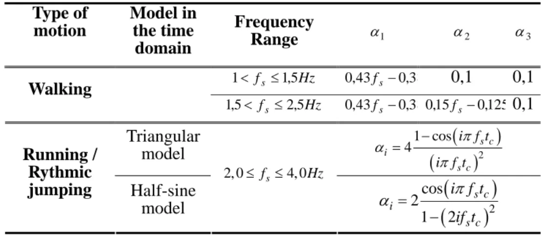
The Fourier coefficients αi may have the values listed in Table 1, according to the type of
pedestrian motion under consideration. In the range 2,0-2,5Hz, different motion types are possible, but running or rhythmic jumping lead to more severe dynamic coefficients than walking. The load function for the former types of motion is different from that of the latter, because it shows a
maximum value corresponding to the contact of the foot with the deck, followed by some time with no contact at all. Such function may, therefore, be modelled as a periodic sequence of triangular or semi-sinusoidal impulses with a duration tc equal to the contact period between the foot and the deck.
Table 1 –Fourier coefficients for the first three harmonics
Type of motion Model in the time domain Frequency Range α1 α2 α3 Hz fs 1,5 1< ≤ 0,43fs−0,38 0,1 0,1 Walking Hz fs 2,5 5 , 1 < ≤ 0,43fs−0,380,15fs−0,1250,1 Triangular model
(
)
(
)
2 1 cos 4 s c i s c i f t i f t π α π − = Running / Rythmic jumping Half-sine model 2, 0≤ fs ≤4, 0Hz(
)
(
)
2 cos 2 1 2 s c i s c i f t if t π α = −Bachmann and Ammann [2] propose the phase angles to be considered with the values φ 1=0, φ 2=
φ 3= π/2. However, this issue will be irrelevant in most situations, except when the response is not
dominated by resonance in one of the load harmonics, which will not be usually the case.
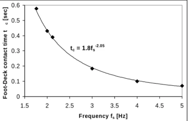
tc = 1.8fs-2.05 0 0.1 0.2 0.3 0.4 0.5 0.6 1.5 2 2.5 3 3.5 4 4.5 5 Frequency fs [Hz] F o o t-D ec k co n tact t im e t c [s e c ]
Figure 1: Foot-to-deck contact period tc
The relation between the foot-to-deck contact period, tc, and the step period, Tp=1/fs , may be obtained from the relation shown in Figure 1.
2.2 Spatial superposition of individual loads
In order to compute the overall effect of more than one pedestrian moving on the deck, a computer programme was developed which overlaps the effects of individual pedestrians.
According to Matsumoto et al (1978) [3], the distribution of step frequencies for pedestrians walking on a footbridge deck may be closely represented through a Gaussian distribution with a mean value of 2,0Hz and a standard deviation of 0,18Hz. As there is no available data concerning the variation of running frequencies, the same distribution function and the same mean to standard deviation ratio was considered for this type of motion.
The recent standard still under approval, prEN1991-2:2001 (EC 1) [4], recommends the
consideration of two dynamic types of load, besides the action of a single pedestrian: one resulting from a group of about 10 pedestrians and the other from a continuous crowd of pedestrians moving on the deck. For the overlap of the individual loads corresponding to single pedestrians, the
previously referred probability distribution law for the step frequency was used.
It was also assumed that the time delay between pedestrian entering on the bridge follows an exponential rule, in such a way that the maximum pedestrian density on the deck is 1,5person/ m2. Considering that there is a trend for people to walk on the right hand side of a footbridge, an asymmetric distribution with the mean value at one quarter of the deck width was considered for the variable that defines the trajectory along the deck of the bridge for each pedestrian.
3.
Vibration limit state in pedestrian bridges
3.1 Maximum values according to EC5 and EC1Both EC1 and EC5 propose expressions for the approximate evaluation of the maximum vertical acceleration resulting from the motion of a pedestrian or a stream of pedestrians on the deck of a footbridge.
In the case of EC5, the numerical procedure for a stream of pedestrians is that of equation (2), in which M = × ×m l b represents the total mass of the deck, l is the span of the bridge, b is its width
and m is the mass per unit area. In the same expression, ζ is the viscous damping ratio, n the number of steps required to cross the bridge, a accounts for the support conditions (see Table 2)
and accounts for the fundamental frequency (see Figure 2-a).
K
,
2 max, , 1 165 n vert vert f a e a k K M πζ ζ − − = (2) For the determination of the effect caused by a pedestrian stream passing on the deck, the following
expression applies: 2 max, , 1 165 0,027 n vert vert f a e a lbk K M πζ ζ − − = × (3) The EC1 proposes an expression similar to these, with only slight modifications in the values of the
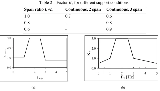
coefficients to be used. The expression (4) is therefore suitable to evaluate the maximum value of the acceleration in the deck, caused by a crowd of pedestrians. In it, the coefficient Kv is obtained from the graphic of Figure 2-b and the remaining parameters are as previously defined.
2 max, 1 210 n vert v e a K M πζ ζ − − = (4) Table 2 – Factor Ka for different support conditions1
Span ratio L1/L Continuous, 2 span Continuous, 3 span
1,0 0,7 0,6 0,8 - 0,8 0,6 - 0,9 0.0 1.0 2.0 3.0 0 1 2 3 4 5 f vert k ve rt ,f 0.0 1.0 2.0 3.0 0 1 2 3 4 5 f v [Hz] Kv (a) (b)
Figure 2 – Relation between coefficient and the fundamental frequency , as prescribed by the EC5(a) and the EC1(b) vertf
K , fvert
4.
Examples
4.1 Structural modelsThe described methodology was used in the dynamic analysis of three types of footbridges
corresponding to simply supported, two- and three-span decks and to a cable-stayed deck. The total length of the deck was kept constant and equal to 30 metres for the different typologies. For multi-span decks, the multi-span length was constant for all multi-spans.
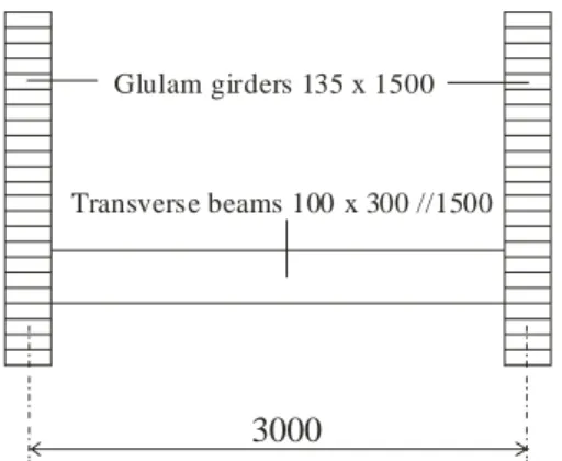
Although the cable-stayed typology is not covered by the specifications included in prEN 1995 or in the prEN 1991-2 it was aimed, with this numerical study, to test their applicability in this case. An asymmetric footbridge, with a main span of 20,0m and a side span of 10,0m was considered. The typical cross section is represented in Figure 6 for the single-span simply supported case. The dimensions of the cross-section for the stiffening girders are given in the table included in Figure 3 for the topologies considered in this study.
1
=1 for simply supported decks.
a K
In order to get comparable results between the different structures, the design was performed under similar serviceability conditions. Main and transverse beams are made of strength grade GL24h glued laminated timber according to EN1194 (2002) [5]. Service class 2 was considered, in terms of the EC5-Part 1. Although irrelevant for this study, it should be emphasized that, in a real situation, the structural elements must be mounted on open air making the consideration of service class 3 compulsory. Concerning the loads, the self-weight and a uniformly distributed live load of 3kN/m2 with short duration was considered.
To generate the dynamic loads a 0.05s time step was considered. Since the time integration using the Newmark method was made for a 0.01s time step, a linear interpolation within the load time step was performed in order to make the integration possible. The damping ratio related to critical damping was considered to be 1%, as recommended by the EC5-2.
Glulam girders 135 x 1500
3000
Transverse beams 100 x 300 //1500
Structural system bxh (mm, girde
Simply supported 135x1500
Continuous, 2 span 135x750 Continuous, 3 span 135x500 Cable-stayed (main span: 6,0-7,5-7,5) 135x400
Figure 3 – Cross section of the deck for all support conditions
4.2 Results and discussion
At this stage the comparison is made between the maximum acceleration values obtained from the load model presented before and those preconized by the Eurocodes EC5 and EC1 as well as those obtained from other codes, namely the British Standard 5400 [6], the Canadian ONT [7] and specialized bibliography (Pernica, [8]).
Following the rules commended by recent pre-standards, prEC5 and prEC1, the load model was applied in three different loading situations concerning pedestrian activity, namely one single pedestrian, one group of 10 pedestrians and finally a constant stream of pedestrians crossing the bridge with a pre-established density over the deck. This density was considered to be 0.5 pedestrians/m2 conducting to about 45 pedestrians simultaneously crossing the 30 meters span bridge.
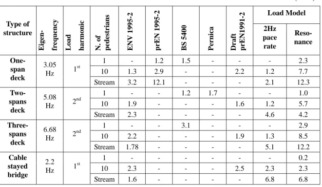
Concerning the data given in Table 3, it should be stressed that distinction was made between the ENV1995-2:1997 [1] and the new project prEN 1995-2 [9], since the clauses concerning continuous beams are withdrawn in the last one. Besides that, the given values refer to maximum acceleration situations, so that the resonance of one harmonic of the load, the first or the second, with the first eigenfrequency is the main loading situation. However, pedestrian bridges are mostly used by “walking” people at pace rates of about 2Hz, so that this situation is also considered in the load model for the groups of people, in order to have reference values for the most probable maximum acceleration in “normal” usage. These results are included in the first column of the Load Model results.
The results from different sources summarized in Table 3 show some scatter, which is not
comprehensible in some cases. As a matter of fact, for the simplest case, the one-span deck loaded with one pedestrian crossing the bridge with a pace rate coincident with the eigenfrequency, the prEN1995-2 gives a substantially lower maximum acceleration (1.2m/s2) than the one computed (2.3 m/s2). However, the value obtained from this code for the effect of a continuous stream of pedestrians acting in resonance with the structure (12.1 m/s2) compares well with that one obtained from the load model (12.3 m/s2).
values obtained from this code compares relatively well with those computed for “walking people” crossing the bridge at about 2 paces/sec. However they are substantially lower than those computed for the situation of resonance, as it can be seen when comparing the correspondent column with the last column in the Table 3.
The methodology given in Pernica [8] is limited to pace rates up to 2.5Hz, so that, in this case it can be applied only in the three-spans deck situation.
Table 3 – Maximum vertical deck acceleration obtained from the different sources (m/s2)
Load Model Type of structure Eig en- fr equency L oad harmonic N. of pedestrians EN V 1995-2 prE N 1995-2 B S 5400
Pernica Draft prE
N1991-2 2Hz pace rate Reso-nance 1 - 1.2 1.5 - - - 2.3 10 1.3 2.9 - - 2.2 1.2 7.7 One-span deck 3.05 Hz 1 st Stream 3.2 12.1 - - - 2.1 12.3 1 - - 1.2 1.7 - - 1.0 10 1.9 - - - 1.6 1.2 5.7 Two-spans deck 5.08 Hz 2 nd Stream 2.3 - - - - 4.6 4.2 1 - - 3.1 - - - 2.9 10 2.2 - - - 1.9 1.3 8.5 Three-spans deck 6.68 Hz 2 nd Stream 1.78 - - - - 5.1 12.2 1 - - - - 0.2 10 2.3 - - - 2.5 2.3 2.3 Cable stayed bridge 2.2 Hz 1 st Stream 1.6 - - - - 6.8 6.8
5.
Conclusions
Some discrepancies were detected when comparing the results obtained from the codes, specially the prEN1995-2 and the draft of the prEN1991-2 and the results from the Load Model presented in the first part of the paper. These discrepancies should be avoided, at least for the simplest situation when only one pedestrian crosses a simply supported bridge.
For groups of 10 pedestrians the prEN1991-2 compares well with the computed values if the dynamic load is due to “walking people” crossing the bridge deck at about 2 paces/sec. In resonant conditions at higher frequencies the maximum acceleration predicted by the load model is much higher than the one predicted by the referred codes.
6.
References
[1] ENV 1995-2:1997 – Eurocode 5: Design of timber structures – Part 2: Bridges [2] Bachmann, H. e Ammann, W., 1987 – Vibrations in Structures Induced by Man and
Machines, Journal of IABSE, Structural Engineering International, vol 5, nº [3] Matsumoto, Y., Nishioka, T. Shiojiri, H. Matsuzaki, K., 1978, Dynamic Design of
Footbridges, IABSE Proceedings, P-17/78, pp.1-15.
[4] prEN 1991-2 (Draft stage 34) – General actions – Traffic loads on bridges; Annex X (informative) Dynamic models of pedestrian loads. (August 2001)
[5] EN1194:1999 - Timber structures – Glued laminated timber – Strength classes and determination of characteristic values.
[6] British Standards Institution, 1978, BS5400, Part 2, Appendix C, Vibration Serviceability Requirements for Foot and Cycle Track Bridges.
[8] Pernica, G. – Dynamic load factors for Pedestrian movements and rhythmic exercises, Canadian Acoustics, pp 18, 2, 3-18,1990.