Abstract
A summary is given of the history of ten European codes for structure design, and their introduction throughout Europe. The main features of EN 1990, ‘Basis of structural design’ and EN 1991, ‘Actions on structures’ are explained.
Examples are given of the wide scope and technical innovations of EN 1993, ‘Steel structures’ and EN 1994, ‘Composite structures of steel and concrete’, with reference also to the concrete code, EN 1992.
There is discussion of the suitability of Eurocodes for use in non-European countries and their relevance for Brazil.
Keywords: Steel structures, composite structures, design, European codes of practice.
The Eurocode System and the codes for
steel and composite structures
(O sistema de Código da Comunidade Européia
(
E u r o c o d e s )
e as normas européias para estruturas de
aço e mistas aço-concreto)
Roger P. Johnson
Emeritus Professor of Civil Engineering, University of Warwick, U.K. E-mail: [email protected]
Resumo
É apresentado um resumo da história dos dez Eurocodes para projeto de estruturas e sua introdução na Europa. São explicados os principais aspectos das normas EN 1990, Basis of structural design, e EN 1991, Actions on structures.
São apresentados exemplos dos objetivos amplos e das inovações técnicas das normas EN 1993, Steel structures, e EM 1994, Composite structures of steel and concrete, fazendo-se referência, igualmente, à norma européia de estruturas de concreto, EN 1992.
Apresenta-se, ainda, uma discussão sobre a aplicabilidade dos Eurocodes em países não europeus e sua relevância para o Brasil.
Palavras-chave: Estruturas de aço, estruturas compostas, dimensionamento, normas européias.
1. Introduction
The Eurocodes have been the subject of much recent publicity in Europe, as all of them are to be published in their final form by the end of 2006. In this paper:
• Some important features of the system as a whole are described, and the extent to which each country can modify it is explained.
• Some of the new terminology and concepts are introduced. • Reference is made to some of the technical innovations. • The problems and benefits of changing to the new system
are discussed.
2. The development of the
Eurocodes
Soon after World War II, bodies such as the European Concrete Committee and the European Convention for Constructional Steelwork began work on new design methods. In 1957, members of the European Union agreed in the Treaty of Rome that barriers to trade should be removed. The differences between national methods for design of structures is such a barrier. In the 1970s, the European Joint Committee for Composite Construction was formed, to prepare a European code. It worked mostly in French and German; but soon after the UK joined the European Union, its working language changed to English. Soon, all the Eurocode work was being done in English. The codes are then translated into French and German. A Eurocode in Portuguese, for example, can be prepared by translation from any one of those three languages. The first draft for Eurocode 4, Composite Structures of Steel and Concrete, was published as a book in 1981. By then the European Commission had set up a Steering Committee to take control of the work on what are now EN 1992, 1993, and 1994, also known as Eurocodes 2, 3, and 4, and as EC2, etc. There was little support from industry. Drafts of these three codes were produced in the early 1980s, intended for both buildings and bridges, and were circulated for national comment - but most countries were not interested.
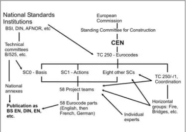
In 1990 the European Commission transferred the work to the European Committee for Standardisation (CEN). It replaced the former Steering Committee with its Technical Committee TC250, with almost the same membership. The objectives of the codes are shown in Figure 1.
The Members of CEN are national standards bodies such as BSI, DIN, AFNOR, etc. And includes some non-EU countries such as Switzerland and Iceland. The Members agree to be bound by the rules and procedure of CEN. Some details are given in Figure 2.
The Eurocode system evolved to that shown in Figure 3.
Figure 1 - Objectives of Eurocodes.
Figure 2 - Rules and procedure.
CEN - Association of BSI, DIN, AFNOR, etc.
Rules and Procedure
• Competing national standards to be withdrawn from use. • No duplication or repetition between standards. • Cross-references for design, materials, testing, etc., only
to CEN or ISO standards, not to national standards. • Drafting in English → French and German.
• ENV stage - voting - draft EN stage - voting - EN. • ENVs and Ens published by NSIs, not by CEN.
CEN Eurocodes EN 1990 to 1999 for
design of structures
Objectives
To remove barriers to trade in construction works within the Eurocodes Union.
To harmonise design philosophy and methods:
• Across structural materials (steel, concrete, timber, masonry, geotechnical, etc.).
• Across types os structure (buildings, bridges, masts, chimmneys, pipelines, foundations, etc.).
• Across Europe from Iceland to Greece, and Latvia to Portugal.
CEN: Association fo National Standards institutions (NSIs).
The original three sub-committees grew to ten. The ‘no duplication’ rule of CEN caused all material-independent rules to be moved to a new code, now EN 1990, Basis of Design. Its main text is also independent of the type of structure, so it has annexes for buildings, bridges, and so on.
As there can be no reference from a Eurocode to national standards, European codes for actions, foundations, and earthquake design had to be added to the codes for steel and concrete. Later, CEN agreed to prepare codes for timber, masonry, and aluminium structures, each with a Sub-committee, and project teams reporting to it. Structures of glass and of fibre composites may be added later.
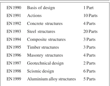
Discussions on the division of the codes into Parts extended for over a decade, and led to the present 58-part system, shown in Figure 4.
Each Part was published as an ENV (preliminary) code, and subjected to national comment and approval by voting. The comments led to major changes from the ENV codes to the final ENs, which went through the same long process. Each country’s national standards body publishes each part, in the language of its choice. Just over half of the 58 Parts have been published by BSI. The target is to have all 58 in print by the end of 2006.
3. Scope, and types of clause
The content of the ten Parts of EN 1991, ‘Actions’ is shown in Figure 5. These are all ‘characteristic’ or ‘nominal’ values appropriate for checks on serviceability. The many types of structure covered is illustrated by the subjects of the 20 Parts of the ‘Steel’ code, shown in Figure 6. The main types of structure not included are those located offshore (oil rigs, etc.) and those used for transport (aircraft, ships, etc.).The ‘no repetition’ rule led to the use of two types of clause: those applicable to all structures in the relevant material (steel, concrete, etc.), known as ‘General’, and those specific only to a certain class of structures, such as bridges. Designers for buildings are fortunate to have their ‘Specific’ rules in the same Part as the General rules, usually named Part 1-1 (with Part 1-2 for Fire); but bridge designers have to cope with a Part 2, ‘Bridges’ that is full of cross-references to General rules in Part 1-1.
From here on, reference will be made only to the first five codes listed in Figure 4. The bridge Parts of the concrete and steel codes, EC2 and 3, failed to agree on a common method for cross-referring to their General rules. Their division into Parts is also different.
In Eurocode 2, everything except Fire, Bridges, and Water-retaining structures is in Part 1- 1, which is 230 pages long. Eurocode 3, for steel, has 20 separate Parts. The length of its Part 1-1 is only 40% of that of the concrete Part 1-1.
Figure 4 - Subjects and Parts of the ten Eurocodes.
Figure 5 - Scope of EN 1991 - Actions.
Figure 6 - Scope of EN 1993 - Steel structures.
EN 1990 Basis of design 1 Part
EN 1991 Actions 10 Parts
EN 1992 Concrete structures 4 Parts
EN 1993 Steel structures 20 Parts
EN 1994 Composite structures 3 Parts
EN 1995 Timber structures 3 Parts
EN 1996 Masonry structures 4 Parts EN 1997 Geotechnical design 2 Parts
EN 1998 Scismic design 6 Parts
EN 1999 Aluminium alloy structures 5 Parts
Scope of EM 1991 - Actions
• Densities, self weight and imposed loads. • Actions from fire.
• Snow, wind, and thermal actions. • Actions during execution (construction). • Accidental actions - impact and explosion. • Traffic loads on bridges.
• Actions in silos and tanks.
• Actions from cranes and machinery.
Scope of EM 1933 – Steel structures
• General rules and rules for buildings.
• Joints, fatigue, tension members, stainless steel. • Cold formed thin gauge members and sheeting. • Fire design.
• Steel bridges.
• Planar plated structures.
• Towers, masts, shells, chimneys, silos, tanks. • Pipelines.
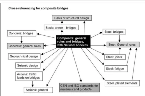
Eurocode 4, composite structures, cross-refers extensively to EC2 and EC3. To assist users, this code was permitted to print its General rules in both Part 1-1 (buildings) and Part 2 (bridges), with identical wording and clause numbering. Even so, the cross-referencing for composite bridges can involve all the code parts shown in Figure 7.
The scope of Eurocodes is far wider than that of the national standards that they replace. As an example, the content of Eurocode 4 is shown in Figure 8. The three methods for fire design are: (a) use of nominal dimensions, as now; (b) graphs and tables based on parametric modelling by computer; and (c) a three-stage finite-element analysis. Types of provision are summarised in Figure 9. ‘Normative’ is the usual name for a clause in a CEN standard. There can be no alternative to a Principle (printed with P after the paragraph number), so the verbal form ‘shall’ is used. Principles rarely include numerical values. Most clauses are application rules, with the word ‘should’. In theory, alternatives to application rules are permitted, but it is rarely practicable to satisfy the conditions for doing so. The clauses that state assumptions are effectively limits to scope. Some of the Annexes are ‘Informative’, which is just what it says - information that can be used without departing from the code.
4. National annexes
National annexes arise from the need of each country to preserve its national sovereignty. The legal status of a Eurocode varies from country to country. Countries have the right to determine their own margins of safety, so the partial factors for actions and resistances appear in the Eurocodes in informative Notes, giving ‘recommended values’ for what are called Nationally Determined Parameters (NDPs).Most existing national codes include some provisions that are not in the Eurocodes. Provided that the material is consistent with the Eurocodes, it can be made a requirement in that country. It
Figure 7 - Eurocode Parts required for design of a composite bridge.
Figure 8 - Example, the content of Eurocode 4.
The scope of EN 1994, ‘Composite structures of steel
and concrete’ include:
• Steels up to grade S460
• Concretes up to grades C60/75 and LC60/66
• Unbraced and braces frames, with simple, semi-rigid, or rigid joints.
• Concrete-encased columns and concrete-filled tubes.
• Partially-encased beams.
• Box girders and composite plates.
• Trusses with either or both chords composite.
• Bowstring arches and half-through bridges with the deck in axial tension.
• Prestress by external tendons or by jacking at supports.
• Resistance of buildings to fire, by three alternative methods.
Figure 9 -Clauses and Annexes in the Eurocode System.
Normative clauses:
Principles - ‘...shall...’
Application rules - ‘...should...’
Assumptions - ‘...it is assumed that...’
Informative annexes (e.g. Creep and
shrinkage of concrete; Brittle fracture;
Filler-beam bridge decks; Statistical calibration)
National annexes – give Nationally
is known as ‘non-contradictory complementary information’, abbreviated to NCCI.
In each country, each code Part has a National Annex. It gives values for the partial factors and other NDPs, and refers to publications that give the NCCI for construction in that country. The Annex is Normative in that country, but ‘Informative’ for any use outside that country. The permitted content of a National Annex is shown in Figure 10.
Any matter that could not be agreed during drafting was given a ‘recommended value’ and became a Nationally Determined Parameter. This was a particular problem for concrete structures, and EN 1992-1-1 ended up with 120 NDPs. The steel code EN 1993-1-1, with 25, is more typical. The seven ways in which its NDPs arose are shown in Figure 11.
In practice, most countries choose the recommended values. Countries that choose other values will be required by the European Commission to justify them, and pressure will be applied for eventual convergence to single ‘European’ values.
5. Terminology,
symbols, and units
A valuable feature of the Eurocodes is that almost complete agreement has been achieved over terminology, symbols, and units; so much so that the symbols are becoming standard usage world-wide at international conferences. Some seem complex, but they provide clear information. Most of the subscripts correspond to English words. The key ones are E for effects of actions, R for resistance, and d for ‘design’ meaning that the relevant partial factor has already been applied.
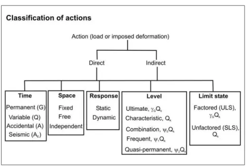
Words are used in the Eurocodes with great precision. ‘Action’ is more general than ‘load’, for it includes anything that causes stress or strain, such as settlement or change of temperature. The classification of actions is shown in Figure 12. Each of
Figure 10 - The permitted content of a National Annex.
Figure 11 - Nationally Determined Parameters (NDPs).
Figure 12 - Terminology for Actions.
National Anneses (Informative) may contain only:
• Values for partial factors and/or classes where alternatives are given in the Eurocode,
(example: exposure class; partial factor for traffic loads). • Values to be used where a symbol only is given in the Eurocode. • Geographical and climatic data specific to the Member State; e.g., a snow map.
• References to Non-Contradictory Complementary Information (NCCI) to assist the user to apply the Eurocode.
Controversial issues - leading to NDPs in national
annexes:
these words has a clear definition, as do the words ‘strength’, ‘resistance’ and ‘capacity’ which in loose English are almost interchangeable.
There are three types of ‘design situation’: persistent, transient, and accidental. Their definitions and those of the two groups of limit states, Ultimate (ULS) and Serviceability (SLS) are shown in Figure 13. These were agreed after extensive study and discussion.
The abbreviations for the four types of ultimate limit state will be unfamiliar, although we design now for the first three: loss of equilibrium, structural failure, and fatigue. The last one, GEO, is needed for the use of limit state design for foundations. It defines a different method of introducing safety margins.
6. Combinations of
actions
A comprehensive system of combinations of actions is defined in EN 1990. This includes alternative combinations for structural failure, as shown in Figure 14 for one permanent action, G, and two variable actions Q, such as floor loading and wind. The first one corresponds to practice in the U.K.: the numbers 1.35 and 1.5 are the partial factors, and 0.7 is the combination factor for the second variable action, Q2. In this expression, ‘+’ means that the effects of the actions (for example, bending moments) are added, not the actions themselves.
The second method is more complex, but corrects the over-conservative assumption that factored values of both G and Q1 will occur at once. It does so by reducing the factor for Q1 in the first equation, and the factor for G in the second, as shown in bold type. The less favourable result is used, but it will always be lower than that from the other method.
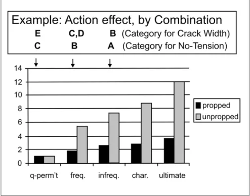
A more complex set of combinations is shown in Figure 15, assuming that the first method is used for the Ultimate Limit
State. This is for a member in a bridge Figure 14 - Partial factors (γ) and combination factors (ψ).
Design situations and limit states
Design situation: a set of physical conditions representing a certain time interval
• Persistent: relevant during most the design working life of the structure. Normal use.
• Transient: relevant during short period, with a high probability of occurrence. During construction.
• Accidental: involving exceptional conditions e.g., fire, explosion, impact, or local failure.
Limit state: a state beyond which the structure no longer satisfies the design performance requirements; for example:
Ultimate limit states: associated with collapse or structural failure. Four types: • EQU: loss of equilibrium of the structure or any part of it, as a rigid body. • STR: failure by excessive deformation, rupture, or loss of stability, governed
by properties of the structural materials.
• FAT: failure caused by fatigue or other time-dependent effects. • GEO: failure or excessive deformation on the ground
Serviceability limit states: conditions beyond which specified service requirements for a structure os structural element are no longer met. Examples: deformation, vibration, local damage.
Figure 13 - Design situations and limit states.
Fundamental combinations of actions for Ultimate
Limit States
Example of alternatives in EN 1990 for STR and GEO limit states
Characteristic actions:G (permanent)
Q1 and Q2(variable), co-existing with Q1 leading
For typical γ and ψ factors for a floor load for a building:
Either:
1.35
G
+ 1.5 (
Q
1+ 0.7
Q
2)
Or the less favourable of:
1.35
G
+ 1.5 (0.7
Q
1+ 0.7
Q
2)
subjected to the variable actions: Vehicle loading, Wind, and Temperature change. For ultimate limit states, one variable action is assumed to be ‘leading’, and is shown in bold type. The other variable actions are reduced by ‘combination factors’, the numbers within the brackets ( ). The Figure shows the Recommended Values, from EN 1990. The three serviceability combinations (SLS) are used for different types of action effect, as shown. All the partial factors for the actions are 1.0 (and so are not shown). The combination factors take account of the expected duration of the action, and hence of the probability that it will be present at the same time as another variable action. The alternatives occur because each variable action is assumed in turn to be the leading action (shown in bold type). For the quasi-permanent combination, the combination factors for vehicle and wind actions are zero. In design for a particular member, it is usually obvious which combination will govern.
Detailed background to this subject is given in the Designers’ Guide to EN 19901.
To show how different the combinations can be, relative values are given in Figure 16 of a bending moment acting on a composite cross-section of a beam, taking the quasi-permanent value (see Figure 15) as unity, for both unpropped and propped construction. The variation is much greater for propped construction because the unit value then does not include the weight of the concrete slab.
7. Technical differences
from existing codes
Some of the design rules that may be unfamiliar are now presented, with reference to steel, concrete and composite structures.
In steel and composite frames, the Eurocodes make provision for the use of three types of beam-to-column joint: rigid, semi-rigid, and nominally pinned.
Figure 15 - Sets of actions for use in design.
Combinations, cases and arregements of actions
Combinations for load case GVWT: permanent (G), vehicle (V), wind (W) and temperature (T):
For ULS (STR): 1.35 G + 1.35 V + 1.5 (0.6 W) + 1.5 (0.6 T)
Or: 1.35 G + 1.35 (0.75 V) + 1.5 W + 1.5 (0.6 T) Or: 1.35 G + 1.35 (0.75 V) + 1.5 (0.6 W) + 1.5 T
For SLS: characteristic: G + V + 0.6 W + 0.6 T for irreversible effects (e.g. yielding)
Or: G + 0.75 V + W + 0.6 T (or similar, with T leading) Frequent: G + 0.75 V + 0.5 T for reversible effects (e.g. deformation) Or: G + 0.2 W + 0.5 T
Or: G + 0.6 T
Quasi-permanent: G + 0.5 T for long-term effects (e. G. creep)
Arragement: G everywhere, even where beneficial; others: only where adverse.
Methods are given for calculating the rotational stiffness of a joint. It is classified according to its initial elastic stiffness, as shown in Figure 17. The class determines how the frame is analysed. There are detailed rules for the important class ‘semi-rigid’, which can provide better economy than the use of simple or rigid joints.
There is great emphasis on ensuring durable concrete. Figure 18 gives an example from the extensive rules on concrete cover to reinforcement, with an exposure in Environment group 4, ‘Chlorides from sea water’, and sub-group XS3. The basic cover, 45 mm here, depends on the concrete mix and the design life. Four of the factors that can modify it are then listed. Finally, there is a correction for quality of execution.
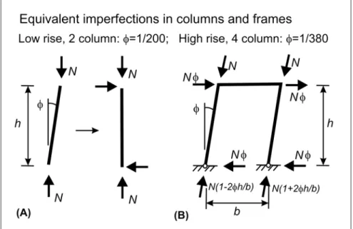
As is well known, resistance to buckling is influenced by imperfections, but it is not always clear in current methods how they are being allowed for. The European column curves, for example, allow for member imperfections (initial bow, etc.) but not for global imperfections, such as out-of-plumb. The Eurocodes allow for an out-of-plumb angle φ, shown in Figure 19, by the application of notional horizontal forces to a frame, as shown on the right. These are additional to any wind loading in the combination considered.
For composite columns, column curves are not used at all. In the example in the left-hand diagram in Figure 20, the 7-m colu7-mn is represented by the x-axis. It has end moments 380 kNm and zero, found from global analysis. Following rules in Eurocode 4, these are replaced by an equivalent uniform moment, the horizontal line, increased at mid-length to allow for the second-order effects of the bending deformation. In the right-hand diagram, the first-order moment from the initial bow of the column, 63 kNm, is increased to 83 kNm to allow for its second-order effect. The column is checked for bending moments given by the sum of the two moment diagrams.
Figure 17 - Types of beam-to-column joint.
Figure 18 - Factors that affect cover to reinforcement.
Duribility of reinforced concrete
Environmental Class: 6 groups, from ‘No risk’ to ‘Chemical attack’
Example: Group 4 ‘Chlorides from sea water’
Sub-group: XS3, ‘Tidal, splash and spray zones’ (e.g., a bridge pier)
Basic cover for XS3: 45 mm with C35/45 concrete and 50-year life
• For 100-year life, ↑ to 55 mm • For C45/55 concrete, ↓ to 40 mm
• For ‘Special Quality Control’, ↓ to 40 mm • For > 4% air entrainment, ↓ to 40 mm
Addition for ‘deviation’ based on CEN Standard for Execution: typically, + 10 mm.
Figure 19 - Global imperfections in columns.
For any design rule that concerns steel or concrete, Eurocode 4 usually refers to the Eurocodes for design in those materials. Where such a rule is difficult to apply to a composite member, Eurocode 4 modifies it. This occurs mainly with the concrete code, where rules on creep, shrinkage and cracking have been simplified. Agreement with Eurocode 3, for steel structures, is very close.
8. Relationship to existing
codes
A designer familiar with the British code for bridge design, BS 5400, would find the changes given in Figure 22 when designing a composite bridge to the Eurocodes. They are so extensive that it is unwise to try to use a mixture of clauses from the two codes. For example, the British highway loadings are replaced by a system that gives each country great freedomto define traffic loading appropriate for the bridge being designed.
The main problems of changing to the Eurocodes, given in Figure 23, have received much publicity. The changeover cost is significant - but change is inevitable, and some national codes have become severely out-of-date while countries waited for the Eurocodes. The other three items will receive much help from publications, new software, and from the many worked examples being prepared.
9. The way ahead
The main benefits from the changeover are given in Fig. 24. Technically, the codes are a great leap forward. They make some provision for the use of finite-element methods. They rely on the availability of elastic critical and second-order elastic programs to make possible the design of a much wider range of structures where the resistance is governed by buckling.
Recent advances in fire engineering can be used. Once the basic methods have been learned, it will be far easier than at present to develop expertise for a wide range of materials and types of structure, so engineers should become more versatile. Young engineers will benefit most, having less to un-learn.
All of us can become better able to compete overseas, and those who have ignored Eurocodes until now risk being un-competitive in international work, because some countries are well advanced in their adoption of the new methods. For example, use of Eurocodes for design of all new bridges in
Figure 20 - Second-order bending moments in a column. Figure 21 - Details susceptible to longitudinal splitting (‘lying studs’).
Figure 22 - Eurocodes compared with National Codes.
Eurocodes compared with National Codes
Changes may include:
• Model for highway loading • Combination rules
• Creep and shrinkage of concrete • Cracking and shear lag in deck slabs • Allowing for second-order effects • Resistance functions
• Fatigue of shear connection • Stress limits for serviceability
Figure 23 - Eurocodes problems.
Eurocodes - problems
• ENs 1990-1994 have over 500 pages - cost? • Longer design time at first - more calculation. • Need ISO and CEN product standards. • Need software for some global analyses.
Figure 24 - Eurocodes benefits.
Eurocodes - benefits
• Integrated, state-of-art, with wide scope. • Use recent advances in fire engineering, etc. • Helps designers to become more versatile. • Similar methods for all materials.
Germany has been mandatory since January 2005, and it is seven years since the Millennium Tower in Vienna was designed by Eurocode methods. There are already signs that their use will spread far outside Europe.
Until now, there has been an awkward inconsistency between design methods for foundations in the UK and those for superstructures. The Eurocodes remove it.
Industry-based organisations, concerned about loss of market share, are competing in the provision of low-cost help to users of Eurocodes. However, employers need to plan expenditure wisely. Attendance at short courses costs both the fee and the lost working time. Written guidance is cheaper and easier to refer to. Much material is likely to be produced in Portugal for the guidance of their own engineers, so language need not be a barrier.
The U.K. has a publication ‘Eurocodes News’. Its November 2005 issue lists 38 publications in the last two years relating to Eurocodes. A series of Designers’ Guides is being published by Thomas Telford. The Guide for Composite Buildings was published in 20042. We have just finished a similar
book on composite bridges3, and there
is a recent textbook for students and young engineers based entirely on Eurocodes4. There are also several
web-based initiatives. Software companies will start work as soon as the national annexes are available, and are well aware that many of their current products will become obsolete.
Each non-European country has to decide whether to adopt these codes. Those countries without modern codes of their own have been the first to do so. Others, such as South Africa, are likely to wait a few years, until more simplified versions, software, and experience of use is available. Each code can easily be modified to suit the special needs of a non-European country and its climate, quality of workmanship, railway loadings, etc., through use of the system of National Annexes.
In a country such as Brazil, would be prudent for each organisation such as a national steel industry to nominate a few people:
• To become knowledgeable and proficient in the use of Eurocodes as soon as possible.
• To use them for fairly small job, perhaps as an exercise.
• To study their wide scope, as this may lead to the use of innovative structures that are economic, but have been avoided until now through lack of design rules.
This should enable the way ahead to be seen more clearly.
Having been involved in work on Eurocodes for over 30 years, the author welcomes questions and discussion, to inform decisions about what needs still to be done.
10. References
1. GULVANESSION, H., CALGARO, J-A., HOLICKY, M. Designers’ guide to EN 1990 - Eurocode: basis of structural
Design. London: Thomas Telford, 2002.
2. JOHNSON R.P., ANDERSON, D.
Designers’ guide to EN 1994-1-1: design of composite steel and concrete structures;
general rules and rules for buildings.
London: Thomas Telford, 2004. p. 246. 3. HENDY, C.R., JOHNSON R.P.
Designers’ guide to EN 1994-2: design of composite steel and concrete structures; general rules and rules for
bridges. London: Thomas Telford,
London, 2006. (To be published). 4. JOHNSON, R.P. Composite structures of
steel and concrete. Beams, columns, frames, and applications in building Blackwell: Oxford, Sept. 2004. (3.ed.). p. 241. Artigo recebido em 07/12/2006 e
aprovado em 29/01/2007.