An Analytical Model to Predict Elongation of Tailor
Welded Blanks [TWB]
Patel V.K.
A, Raval H.K.
BAbstract:
Tailor Welded Blanks (TWBs) made of dissimilar, uniform or non uniform thickness materials have potential applications in automobile industries for light weight materials in order to improve fuel efficiency and cost of carrier.
The focus of this paper is to develop and present analytical model to determine total elongation of tailor welded blank (TWBs). The validation of this method is done by experimentally evaluated result.
In this present work, an analytical model to predict the total elongation of tailor welded blank at ultimate strength is reported. The analytical model reported was validated by comparing the values with experimental results. Comparison with experimental results demonstrates the accuracy of this methodology. The analytical model provides designers a valuable tool to determine the selection of material combination and thickness combination for given total allowable elongation of TWBs. The methodology presented here has the potential to be extended to analyze a blanks made by more than two material combination.
Index Terms:Analytical Model, Tailor Welded Blank, Uniaxial Tension Test.
I. INTRODUCTION
In recent years, the automotive industry has paid a great deal of attention to weight reduction and fuel economy. In these contents Tailor Welded Blanks (TWBs) made of dissimilar, uniform or non uniform thickness materials have potential applications in automobile industries for light weight materials in order to improve fuel efficiency and cost of carrier. TWBs are commonly used in automotive panels manufacturing. A TWB is composed of more than two materials with similar or different strengths or thicknesses joined together to form a single part before the forming operation. From the middle of the 1980s, tailor-welded blanks have been used increasingly as new technology in the production of automotive components in the USA, Europe and Japan. At present, both research results and stamping practice demonstrate that the tailor-welded blank can be applied successfully in the manufacture of the automotive
[A] Patel V.K. is the M.Tech. student with the S.V. National Institute of
Technology, Surat, Gujarat, India (phone: +919879199149; e-mail: [email protected]).
[B] Raval H. K . is professor in Mechanical Engineering Department with
the S.V. National Institute of Technology, Surat, Gujarat, India (phone: +919824400337; e-mail:[email protected])
components. Some examples of car components made of tailor-welded blanks are the A, B and C pillars situated at both sides of the doors, inner door panels, longitudinals, cross rail bumpers, floor panels, wheel housings, inner panel tail gates, and so on. Recently, there has been increasing use of the welding together of aluminum, magnesium and high strength steel blanks to produce the tailor-welded blanks in order to obtain the maximum weight and strength advantage[1]. The main advantage of using a TWB is that it gives thicker or stronger materials at critical parts of the sheet metal blank. This can also reduce the weight of automotive panels. [1] However, the critical properties of tailor-welded blanks introduce many challenges into the manufacturing process, compared to those for homogeneous materials. The basic factor influencing the formability of tailor-welded blanks is the hardening of the weld joint and the heat-affected zone during the welding process[1], and uneven strain distribution in forming blank. So it is require to pay attention of stress and strain states of TWB during forming for success of forming process. Brad L. Kinsey and Jain Cao[1] have developed analytical model for weld line movement and forming height for TWB in deep drawing operation. S.M.Chan, L.C.Chan and T.C.Lee[7] have done experiments on TWB with different thickness ratio for their study on forming limit diagram. Most researchers have only studied the sheet-thickness effect on the base metal instead of performing a similar study on TWBs. In this study, the focus was made to develop an analytical model to find elongation; stress and strain of TWB for uniaxial test and results of model was compared with experimentally evaluated results of TWB.
II. EXPERIMENTAL WORK
Experiments related to TWBs, made by SMAW, are carried out at the Institute, for different thickness combination of blank to observe failure pattern of Tailor Welded Blank. The blank used to study is as shown in figure 1. The results are used to relate the developed analytical model.
A. Test Piece Material:
The material used in present experiment is SS304, widely used in fabrication of chemical process equipments, like condenser, nucleate filter, blender etc., due to its good corrosion resistance properties which is prime requirements to handle corrosive chemicals, and strength which is require to handle high pressure and high external load.
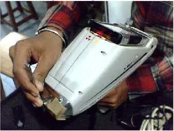
Prior to fabrication of test pieces, material testing was carried out to find chemical composition. Material testing is carried out using X-Ray alloy analyzer as shown in figure 2. The prime advantages of these alloy analyzers are, it uses non destructive testing, results are falling in very narrow standard deviation and very user friendly device.
Fig. 2: Material Testing Using X-Ray Alloy Analyzer
The chemical composition obtained for base metals (i.e. SS304) are listed in following tables.
Table I : Material Testing Report
CLASS : IRON SS : 304
ELEMENT % STD. DEV
1 Fe 71.6 0.36
2 Ni 8.3 0.14
3 Co 0.7 0.98
4 Mo 0.2 0.11
5 Cr 17.6 0.17
6 Mn 1.2 0.15
7 Cu 0.2 0.43
The sheets of SS304 used for SMAW welding were cut into different dimensions with thickness ratio of 0.64, 0.67 and0.78. These different thickness ratios of the TWBs were analyzed by uni-axial tensile test. The thickness combinations of TWBs are shown in Table II:
Table II : Different Thickness Combination Of TWBs Used In Experiment
TWB
No. Blank : 1 Blank : 2
Thickness Ratio
1 1.8 mm 2.3 mm 0.78
2 1.8 mm 2.7 mm 0.67
3 1.8 mm 2.8 mm 0.64
B. Preparation of Specimens:
The dimensions are taken as per ASTM standards of “Standard Test Methods for Tension Testing of Metallic Materials”, Designation: E 8/E 8M – 08 [4]. The base material properties are derived by experiments and same properties are used in analytical calculation of different parameters of Tailor Welded blanks. The dimensions used to find base material properties are shown in figure 3 and 4.
All Dimensions are in mm
Fig. 3: Blank Dimensions used to derive Material properties.
Fig 4: Test Pieces Used in Experiment C. Experimental Set Up:
Experiments were carried out in laboratory of the institute on Tensometer (K I P L - PC2000) Of 2 tone capacity. The tensile testing was performed at the moderate speed available with tensometer (i.e. 1.5 mm/min).
The test was conducted until the occurrence of localized necking and extended up to fracture. Figure 5 shows the experimental set up used.
III. EXPERIMENTAL RESULTS:
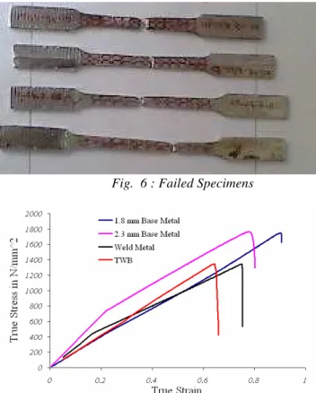
Figure 6 shows deformed tailor-welded tensile specimens of Both base metals, longitudinal TWB and transverse TWB. It also shows that the failure occurs on the thinner part of the tailor-welded tensile specimens. Figure 7 to 9 shows tensile strength comparison of both base metals, longitudinal TWB and transverse TWB in form of stress vs strain relationship for different thickness ratio. Also value of K and n, derived from graph, of base metal are indicated in figure for the assumed material characteristics of
n
K
σ
=
ε
.
Fig. 6 : Failed Specimens
Fig. 7: True Stress-True Strain curve for Base Metals, Longitudinal welded TWB and Transverse Welded TWB with thickness combination of 1.8 mm and 2.3mm.
Fig. 8 : True Stress-True Strain curve for Base Metals, Longitudinal welded TWB and Transverse Welded TWB with thickness combination of 1.8 mm and 2.8mm.
Fig. 9: True Stress-True Strain curve for Base Metals, Longitudinal welded TWB and Transverse Welded TWB with thickness combination of 1.8 mm and 2.7mm
The values of K and n were found from these stress strain graphsas per the method suggested in ASTM standards of “Standard Test Method for Tensile Strain-Hardening Exponents (n -Values) of Metallic Sheet Materials” [4]. The values obtained for these test piece materials are listed in following table III.
Table III : The Values Obtained Of K And n Of Test Piece Materials
Thin Blank Thick Blank Thickness
Ratio Th. Of [Thin /
Thick] blank K
N/mm2 n
K
N/mm2 n
0.64 [1.8/2.8] 2024.1 0.9792 3357.9 0.9408 0.67 [1.8/2.7] 1755.7 0.8264 2299.8 0.7558 0.78 [1.8/2.3] 1857.0 0.9598 2075.4 0.7527
IV. AN ANALYTICAL MODEL TO FIND STRESS STATES OF TWB:
The aim of the present analytical model is to calculate the total Elongation of Tailor Welded blank at the time of maximum force. The present model also calculates, maximum force can be taken by TWB, maximum strain develop in thick blank, Instantaneous length of TWB at time of maximum force, etc. for complete stress state of TWB. A. Analytical Model:
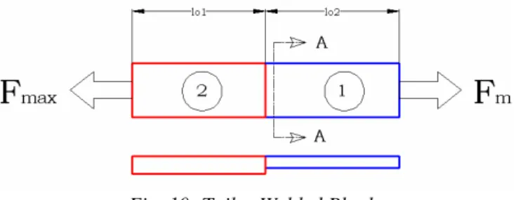
Fig. 10: Tailor Welded Blank
Thin Blank, i.e. blank 1 is the weak portion of the TWB soHence, analysis is done when thin blank reaches the maximum force (Fmax)
B. Input Parameters:
For Thin blank 1 1 1 1 1max sec o o Strength co efficient K Strain Hardening Exponent n Original Length l
Original cross tion Area A Maximum True Stressσ
−
−
For Thick Blank
2 2 2 2 sec o o
Strength co efficient K
Strain Hardening Exponent n
Original Length l
Original cross tion Area A
−
−
The strength co-efficient K and Strain hardening exponent n of both the blanks are calculated from experiment assuming power law material behavior. Also maximum stress that can resist by thin blank is also obtained from experiment.
C. Maximum Force Withstand by Thin Blank:
As shown in figure 10, as force applied on blank is increased the stage will reach when the stress developed thin blank reaches at its maximum value. As resisting area for thick blank is more hence stress states may not reach up to its critical value. Lets consider thin blank at force Fmax, stress induced in thin blank reaches at its maximum value. From the fundamental equation, for thin blank, it can be written as, max max 1 i
F
A
σ
=
,where,
max
1
σ
= Maximum Stress in Blank 1[Thin Blank],
F
max = Maximum Force on TWB,
A
i = Instantaneous c/s area of thin blank side atFmax, max max max 1max 1 1 max max 1 1 1 1 1 1 1 1 1max
max 1 1 1
,
,
ln
,
i
o o
o o i i
i
o o i
o o n n o
F
A
A l
As A l
A l
l
A l
l
As
l
e
l
K
A
F
As
K
e
ε εσ
σ
σ
ε
ε
σ
ε
∴
=
×
=
×
=
=
×
=
×
×
×
∴
=
=
×
Where, A01 = Original c/s area of thin blank,
l01 = Original length of thin blank portion,
ε
1max = Maximum true strain in thin blank. From the above equation it is possible to find maximum force that can be withstand by TWB.D. Strain Developed In Thick Blank:
As discussed earlier, due to more resisting c/s area of thick portion, stress state may not reach at maximum value at Fmax. To find total elongation of thick blank portion, it is required to find strain state of thick blank portion at this force. The, true stress induced in thick blank portion can be written as, max 2 2 i
F
A
σ
=
,Where,
σ
2 = True stress develop in thick portion at Fmax, 2i
A
= Instantaneous c/s area of thick blank at Fmax,
2 2
2
2
max
2 2 2 2 1 2
2
2 2 2 max 2
2 2 2 max 2
max
2 2 2
2 2
,
log ,
ln ln ln ln ln
ln ln ln ln
ln ln
n
o o i i
o
o
o
o
F e
K As A l A l
A
Taking on both sides
K n F e A
n F A K
F n A K ε
ε
ε
ε
ε
ε
ε
ε
× ∴ × = = ∴ + = + − ∴ − = − − ∴ − = ×From the above equation true strain [
ε
2] developed in thick blank at Fmax can be calculated.Using maximum true strain developed in thin portion and true strain develop in thick portion at Fmax The total instantaneous length of TWB can e calculated by,
1 2
1 2
1 2
iTWB i i
o o
l
l
l
l
e
εl
e
ε=
+
=
×
+
×
Where
l
i indicates instantaneous length of subsequentThe Instantaneous length of thin blank at the time of maximum force can be calculated by
1
1 1
1 1
1 1 1 1 1
1
1 1
, ;
i o
o o o o o
i
i o
l l e
So Instantaneous Area of Thin Blank
A l A l A
A
l l e e
ε
ε ε
= ×
= = =
×
The Instantaneous length of thick blank at the time of maximum force can be calculated by,
2 2
2 2 2
2 2 2 2 2
2
2 2
, ;
i o
o o o o o
i
i o
l l e
So Instantaneous Area of Thick Blank
A l A l A
A
l l e e
ε
ε ε
= ×
= = =
×
The engineering and true strain developed in TW can also e calculated by,
TWB TWB
oTWB
l
e
l
∆
=
Where,
∆
l
TWB=
l
iTWB−
l
oTWBV. VALIDATION OF AN ANALYTICAL MODEL WITH EXPERIMENTS:
The model / methodology described in previous section was validated by comparing values with experimental data. While comparing, various parameters where calculated at the maximum stress value recorded during experimentation. Following table IV to show the comparison for different thickness ratio.
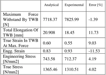
[1] Comparison between analytical model result and Experimental results for thickness combination of 1.8 mm and 2.8 mm.
Table IV : Comparison Between Analytical Model Result And Experimental Results For Thickness Combination Of 1.8 mm And 2.8 mm.
Analytical Experimental Error [%]
Maximum Force Withstand By TWB [N]
7718.37 7825.99 -1.39 Total Elongation Of
TWB [mm] 20.908 18.45 11.73
True Strain In TWB
At Max. Force 0.60 0.55 9.03
Engg. Strain 0.83 0.93 -11.53
Engineering Stress
[N/mm2] 743.58 712.37 4.19
True Stress
[N/mm2] 1365.46 1310.51 4.02
[2] Comparison between analytical model result and Experimental results for thickness combination of 1.8 mm and 2.3 mm.
Table V : Comparison Between Analytical Model Result And Experimental Results For Thickness Combination Of 1.8 mm And 2.3 mm.
Analytical Experimental Error [%]
Maximum Force Withstand By TWB [N]
7702.52 7998.16 -3.83 Total Elongation Of
TWB [mm] 22.90 22.14 3.32
True Strain In TWB
At Max. Force 0.65 0.63 2.46
Engg. Strain 0.91 0.88 3.32
Engineering Stress
[N/mm2] 683.57 799.81 -17.00
True Stress
[N/mm2] 1309.95 1338.59 -2.18
[3] Comparison between analytical model result and Experimental results for thickness combination of 1.8 mm and 2.7 mm.
Table VI : Comparison Between Analytical Model Result And Experimental Results For Thickness Combination Of 1.8 mm And 2.7 mm.
Analytical Experimental Error [%]
Maximum Force Withstand By
TWB [N] 6906.89 7070.85 -2.37
Total Elongation
Of TWB [mm] 17.60 20.98 -19.21
True Strain In TWB At Max.
Force 0.53 0.60 -14.33
Engg. Strain 0.70 0.83 -19.21
Engineering
Stress [N/mm2] 656.29 589.23 10.21 True Stress
[N/mm2] 1118.38 1235.84 -10.50
From the above comparison it is found that results of analytical model is in acceptable limit with that of experimentation.
VI. CONCLUSION:
From Above comparison it is observed that good agreement between Analytical method proposed and experimental results can be obtained which provide sufficient validity of analytical method
the present derivation only two blanks are considered but it is possible to derive similar equitation for multiple blanks. It can be extended for n number of TWB
In the present model, properties of weld are ignored. But it can be taken care by considering weld portion as third portion of TWB by applying all properties of weld to this portion
VII. NOMENCLATURE:
max
2 1
max
2
2
: 1, [ / ]
: , [ ]
: , [ ]
: , [ ]
: , [ ]
: , [ ]
: i
i
o
o
Maximum True Stress in Blank N mm F Maximum Force Withstand by TWB N A Instantaneous Area of Blank mm l Instantaneous Length of Blank mm A Original Area of Blank mm l Original Length of Blank mm σ
ε
2 ,
: , [ / ]
: ,
: .
True Stain of given Blank
K Strength co efficient of given Blank N mm n Strain Hardening Exponent of given Blank e Engineering Strain of given Blank
−
VIII. REFERENCES
[1] H.M. Jiang a, S.H. Li b, H. Wua, X.P. Chena, “Numerical simulation and experimental verification in the use of tailor-welded blanks in the multi-stage stamping process”, Journal of Materials Processing Technology 151 (2004) 316–320.
[2] Brad L. Kinsey, Jian Cao, 2003, “An Analytical Model for Tailor Welded Blank Forming”, ASME, Journal Of Manufacturing Science And Engineering. Vol. 125, May 2003.
[3] Alan Hannon, Peter Tiernan, “A review of planar biaxial tensile test systems for sheet metal”, journal of materials processing technology 1 9 8 ( 2 0 0 8 ) 1–13.
[4] “Standard Test Method for Tensile Strain-Hardening Exponents (n -Values) of Metallic Sheet Materials1”- ASTM Standards. Designation: E 646 – 00. Nov 22 04:29:02 EST 2007.
[5] “Standard Test Method for Determining Forming Limit Curves” - ASTM Standards. Designation: E 2218 – 02. Nov 22 04:29:02 EST 2007.
[6] Sushanta Kumar Panda, D Ravi Kumar, Harish Kumar, A.K.Nath, “Characterization of tensile properties of tailor welded If steel sheets and their formability in stretch forming ”, Journal of Materials Processing Technology, 2007, 321-332
[7] S.M.Chan, L.C.Chan, T.C.Lee, “Tailor Welded Blanks of Different Thickness Ratios Effcts on Forming Limit Diagrams”, Journal of Materials Processing Technology, 132 (2003) 95 -101.
[8] Shimamoto, A., Shimomura, T., Nam, J., 2003. “The development of a servo dynamic loading device”. Key Eng. Mater. 243–244, 99–107.
[9] R. Padmanabhan, A.J.Baptista, M.C.Oliveria, L.F.Menezes, “Effect of Anisotropy on the deep-drawing of mild steel and dual phase steel tailor welded blanks”, journal of materials processing technology 184(2007) 288-293.