© 2013 IBRACON
Indirect tensile strength is not usually used for concrete mixtures proportioning and its technological control; lexural strength tests under third point loads arrangement are the pattern for such goals. Indeed, neither of such tests have the capability to set up the actual strength of a concrete slab since its response is under plane stress state. A critical review of the basic concepts on both kinds of tests allows foreseeing its limitations as well as how to overcome such shortcomings. At last correlations between the two kinds of tensile strength are presented considering dry and plastic concretes typically applied on paving, corroborating to former results achieved for plastic concretes.
Keywords: indirect tensile strength; lexural strength; brazilian split test.
Medidas de resistência à tração indireta não são normalmente cotejadas na dosagem ou no controle tecnológico de concretos em pavimentação; os resultados de ensaios de resistência à tração na lexão, em especial com dois cutelos, são empregados para tais inalidades. Na realidade, nenhum de ambos os tipos de teste mede de fato a resistência real do concreto acabado na forma de placa por não representarem um compo-nente estrutural que responde mecanicamente em estado plano de tensões. Uma revisão crítica dos conceitos relacionados a essas medidas de resistência permite claramente enxergar as limitações de cada uma das formas de aferição da resistência à tração e as maneiras de melhor encaminhar avaliações dessa natureza. Correlações entre ambas as medidas por meio de ensaios em concretos secos e plásticos especíicos para pavimentação são apresentadas, corroborando com resultados anteriores obtidos para concretos plásticos.
Palavras-chave: resistência à traçãona lexão; resistência à tração indireta; ensaio brasileiro.
Relations between indirect tensile and lexural strengths
for dry and plastic concretes
Relações entre resistências à tração indireta e à tração
na lexão em concretos secos e plásticos
J. T. BALBO a
a Universidade de São Paulo, Escola Politécnica, Departamento de Engenharia de Transportes, São Paulo, SP, Brasil
Received: 10 May 2013 • Accepted: 02 Oct 2013 • Available Online: 12 Dec 2013
Abstract
1. Introduction
In general, users of concretes made with hydraulic binders (for paving) has the concept that the material is not capable of resist-ing tensile stress since such strength is much lower than the com-pressive strength of concrete. However, from the point of view of cracking in early ages, the material would require investigation on tensile strength, since the drying shrinkage occurs exactly by imposing tensile stress ields on concrete in the early stages of hardening. Both aspects, curing and inal property of hardened concrete are of special consideration in concrete paving when cracks resulting from tensile stresses must be strictly controlled: either shrinkage, by its purposeful induction in well-deined posi -tions, or early manifestation of fatigue, when static strength in-tensely inluences such behavior.
Troxellet al. [1] quotes studies that had previously established that, on average, the concrete tensile strength (direct) would be around 9% of its compressive strength. For concretes with low consump-tion of cement and dry Balbo [2] reached the same ratio (8.9%) studying cement treated crushed stone (named BGTC in paving, blend with well-graded partcles size and cement consumption of 85 kg/m3, very close to compacted concrete, used in dams, and compacted in optimum moisture content in modiied energy). How -ever, the direct tensile tests have never been considered as an element for measuring concrete strength (Troxellet al. [1]) and they also encounter dificulties related to the heterogeneity of the specimens (Balbo [2]), which cause irregular rupture surfaces and sometimes outside the half-height of the sample, which accord-ing to Bazant and Cedolin[3], supported by Fracture Mechanics concepts, raise serious doubts on interpretation and acceptance of such results. Metha and Monteiro [4] claim that the fasteners (by gluing) of cylindrical specimens for the direct tensile testing impose stress ields at the ends that cannot be ignored on the results inter -pretation. In summary, the samples preparation for testing in direct tensile tests requires much more care and attention to details that may invalidate the results obtained (Newman and Bennett [5]). Traditionally, with apparent legacy of the German European school (Balbo [6]), the measurement tensile tests in bending on prismat-ic specimens were quprismat-ickly shaded, in the early 20 century in the dosage and for the technological control of concretes produced for slabs paving. Such tests are normally carried out by applying a central load (one cleaver or center-point load) or with two load points on the thirds of the support span of the prismatic sample (two cleavers or third-point load, is meant here in the third of the span), the latter being more commonplace. In this article, the con-crete tensile strength measured by bending tensile tests (with a cleaver) and diametral compression tests are compared, and also it addresses the differences between the stress ields imposed on concrete samples in each type of test. At the end, the results are confronted with an indication of possible relationship between such strengths to a considerable number of test samples.
2. Determination of indirect tensile
strength – Brazilian test
Fernando Luiz Lobo Barbosa Carneiro [7] faced with the need to check the ability of concrete rolls for the displacement of São Pe-dro Church in Rio de Janeiro (in 1943), employed the diametral compression test on concrete rollers with 600 mm in diameter,
and observed theoretically that (from previous studies in Theory of Elasticity) the vertical distribution of stresses in the load imple-mentation plan during the rupture of the samples would be uni-form (Metha and Monteiro [4], cf. p. 74). The results were initially published in France and later adopted internationally, being com-monly termed by “Brazilian test”. Currently, in Brazil this testing is regulated by NBR 7222 of the Brazilian Association of Technical Standards (ABNT [8]).
According to the American Society for Testing of Materials (ASTM), the tensile strength measured by Brazilian test (or split test) is usu -ally greater than the direct tensile strength of the material (ASTM, 2004). Balbo [2] worked with both types of tests for the analysis of tensile strength of BGTC (cement treated crushed stone, as de-ined earlier), composed of well-graded aggregates and 4% of ce -ment (CP II E 32)consumption by weight; for a supposed type of concrete with low cement consumption as the BGTC, in addition to conirm the assertion of ASTM mentioned above, a great dif -iculty of devising a test in direct tensile was observed, because, of course, during this type of test, samples broke in their weakest sections, namely in areas which have received less compaction energy (blows) during cylinders molding. For a series of identical samples, the value of fct,sp was 2,3 (with a coeficient of variation of 15%), while for direct tensile tests was obtained an average value of 1.2 (3.5% coeficient of variation), establishing the relationship that follows:
(1)
spct
ct
f
f
=
0
,
52
´
,Fusco [9] suggested for conventional concrete buildings the relation:
(2)
spct
ct
f
f
=
0
,
85
´
,Both equations above denote that the indirect tensile strength is higher than the direct tensile strength, which is usually explained by the fact that on the direct tensile test, the rupture plan is weaker and perpendicular to the direction of force application. In the Brazil -ian test (diametral compression test or indirect tensile testing) the cylindrical sample, with extreme parallel plans, is subjected to a di-ametrical compression effort applied over a small width throughout its length, evenly, and this restricted load application area helps avoid the stresses concentration in addition to compensate small irregularities on the surface of the sample. Proveti and Michot[10] point out that this test allows a fracture test in mode I (pure stress) and that the stress ield in the loading implementation plan is quite uniform, thus the test is it for study of brittle materials fracture. Although it is not for everyday use in the concrete area, it is widely used on tensile strength measurement of asphalt concrete, aggre-gates and soils stabilized with hydraulic binders, and for analysis of rocks (especially its vertical strata).
856 IBRACON Structures and Materials Journal • 2013 • vol. 6 • nº 6
the locus of points featuring the same deformation or the locus of points with maximum tangential stress [12]. The tensile areas show that the variation of horizontal deformation (u) relative to axis y is null in practice; in other words, the tensile deformations maintain constancy perpendicular to the vertical axis in the loading direc-tion. The stress in the directions x (tensile) and y (compression) are determined very simply, according to Timoshenko[11]:
(3)
22 2
2 2
.
4
.
4
.
.
.
.
2
÷÷ø
ö
ççè
æ
+
=
x
d
x
d
h
d
F
x
p
-s
(4)
÷÷ø
ö
ççè
æ
+
=
1
.
4
4
.
.
.
.
2
2 2
2
-x
d
d
h
d
F
y
p
s
From the equation [3], it is observed that the stress in the direction x is dependent on the distance from the center of the disc, and if taken as x = 0, results in maximum tensile strength, constant along the axis y (independent of y), as follows:
(5)
h
d
F
x
.
.
.
2
p
s =
The Figure 2 shows isotension fringes patterns during a diametral disk compression test [12]. Unlike tensile test for concrete, the di-ametral compression test is considered to be useful and reliable for the estimation of the other conventional concrete strength, that is, bending tensile strength, and even to compression [1]. Thus, and compression were also studied by means of Photoelasticity in
1948 by Frocht [12] and also by Durelli and Parks [13]. The defor-mation ields measured by photoelasticity with their fringes, typical of a disk subject to diametral compression, are shown in Figure 1. Fringes, which are the dark background areas, are interpreted as
Figure 1 – Fringes for tensile strain fields (left) and compression strain fields (right)
in diametral compression test (extracted from: Durelli e Parks [13])
IBRACON Structures and Materials Journal • 2013 • vol. 6 • nº 6
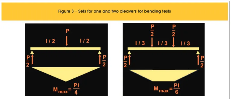
Figure 3. The basic rupture characteristics to each of the arrange-ments shown are:
n One cleaver test: tendency to rupture in the central section of maximum bending moment, however not mandatory. The strength, if the rupture occurs outside this section, must be estimated linearly according to the bending moment that occurs in breaking distance considered from the nearest support;
n Double cleaver test: there’s one middle third of the beam
request-ed by constant bending moment, which gives greater assurance on stress measurement of lower magnitude, as the material breaks at a load to the vertical section theoretically weaker. The Figure 4 shows a photoelasticity test result [14] for a bending beam, similar to a double cleaver test, with support at the ends of the beam of 25 mm high and 300 mm span between supports. Fringes are parallel and their spacing and widths increase as it approaches the span center, maximum tensile request zone on lower iber. The lack of parallelism of these fringes in this central area of the bending beam relates not only to the curvature of the beam (that leads to the tendency to rotate the fringes), but also with the vertical deformations in the region that produce the shape of elliptical arcs [14]. The tensile stress ield during the bending test is very different, and also for this point of view, the diametral compression test.
there is no use reference of this test as a measure standard, but as a means to estimate the other strengths given its execution simplicity, in particular, if compared to the bending tensile test. Krishnayya and Eisenstein [14] point out that, although the Brazil -ian test cannot completely replace other types of tensile tests, it allows more reliable determination of the tensile strength than the direct tensile testing or double punch, while that for analysis of real dams the bending test was inappropriate. Also, the bending test would be most affected by compression planes of the material in beams compared to the uniform distribution of tensile stress in Brazilian test. Aydin and Basu [15], also with focus on uniform ten -sile distribution, concluded that the test is quite useful for verifying micro-structural damage conditions with laws in rocks samples, and weathering-related cracks. Fairhust [16] indicated that, for brittle materials, special attention would be required in the test ar-rangement to avoid tangential stress at the edge of the cylinder, because they would signiicantly change the stress distribution in the sample, rendering the equations 3 and 4 above invalid.
3. Determination of bending tensile strength
The bending tensile test, depending on the use of one or two cleavers, imposes different moments of rupture as described in
Figure 3 – Sets for one and two cleavers for bending tests
858 IBRACON Structures and Materials Journal • 2013 • vol. 6 • nº 6
Tensile stress at bending in the lower iber of the beam is calculat -ed under the good assumption that the neutral line is at mid-height of the cross-section and the stress distribution is triangular. The section of the beam has moment of inertia in relation to the position of neutral line bh3/12. The stress, at the lower iber with distance z from the neutral line is then calculated, for a single and double cleaver test, respectively, is as follows:
(6)
2 3
3 max
2
3
2
12
4
12
bh
Pl
h
bh
Pl
z
bh
M
´
=
´
=
=
s
(7)
2 3
3 max
2
12
6
12
bh
Pl
h
bh
Pl
z
bh
M
´
=
´
=
=
s
As the strength is theoretically equal to the same concrete of the same beam, the double cleaver test requires more load to the rupture of the material in comparison with the test of a single cleaver with the equation [6] having a multiplier of 50% of the actual value of the load. However, given the practical advantage of being much more likely in a single cleaver test, the specimen breaks off the central section than in the double cleaver test, in which the specimen breaks off the middle third, a double cleaver test is more convenient in terms of direct re-sponse (calculation of rupture stress). The rupture stress is deined as the bending tensile strength (NBR 6118) – fct,f – also known as modu-lus of rupture (less precise than the previous expression).
In Brazil, the Standard for implementation of this testing is the NBR 12142 [17], in which specimens with cross-section of 150 x 150 mm are recommended. In the Standard ASTM C 78-09 [18], there is greater lexibility as to the size of the sample. In fact, Cervo [19] study -ing conventional high-performance concrete for pav-ing, from dosages used for construction of two concrete loors, noted that there is no sig -niicant difference to make the use of 100 x 100 mm reduced dimen -sions specimens prohibitive, based on tests with the two dimen-sions of cross sections mentioned and in statistical study on the dispersion of the results (Figure 5). Tests of Kolmogorov-Smirnov on the results determined normal distributions with signiicance levels greater than 0.05. Strengths between two sets of specimens of the same concrete, but with different dimensions, underwent hypothesis testing ”t” as in
Student, conirming that there were no differences between the sets
of data on bending tensile strength of these specimens. This gener-ated great conidence, from then on, for the use of specimens of 100 x 100 mm dimensions in cross section, what has been incorporated since then in the technical community with regard to concrete paving in Brazil, using the same formulas for calculating as the NBR 12142 Standard [17]. The issues regarding the specimen dimension tran-scend a testing performance on specimens of dimensions apparently suitable, as it is discussed in the following item.
3.1 Dependence of tensile strength in the sample size
According to Troxell et al.([1], cf. p. 254) the scale effect on beams for bending tensile test takes place analogously to the case of specimens for compression tests: the larger the sample the lower the rupture stress on the test. Bazant and Novak [20], systemizing numerical, analytical, and experimental researches about bending tensile test concluded that the common point between various sur-veys was that the bending tensile strength of the material would decrease with height increase (the cross-section) of the beams, although this scaling factor can be better veriied in comparing the strengths between beams of clearly different heights (as 75 mm – minimum conventional height of the beam – and 250 mm, thick-ness of a simple concrete pavement). This is shown in Figure 6,
Figure 5 – Relation between strengths
for different beams (source: Cervo [19])
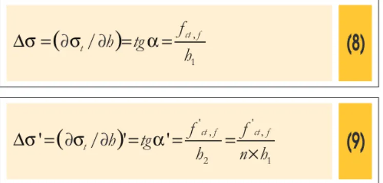
which indicates a decrease in bending tensile strength due to the increased in the cross section of the specimen (in this case, the height of the beam), in comparison with the constant tendency of tensile strength values through Brazilian test. These differences are intuitively understood when the stresses distribution ield in Brazilian test are considered (see Figure 1), very uniform, as com -pared to the stress distributions on the pulled-out bottom lange of beams, as shown in Figure 7. The triangular distribution (approxi-mate), below the neutral line, for two beams of different heights h1 and h2 cause angles of dip on the tensile stress distribution, respectively, of α and α’, and fct,f is confused with the applied stress (σt) in the igure. Stress variations along the triangular distributions presented are, respectively,
(8)
(
)
1 ,
/
h
f
tg
h
ct ft
=
=
=
D
s
s
a
(9)
(
)
1 , '
2 , '
'
'
/
'
h
n
f
h
f
tg
h
ct f ct ft
=
=
=
´
=
D
s
s
a
Notice that h2 is greater than h1 by n times, where n is a real num-ber. Particularly, ∆σ’ is smaller than ∆σ; that is, the peer-to-peer tensile stress variation is smaller in height beam h2 greater n times than h1. The physical consequence of this characteristic of stress distribution in beams of greater height is that the critical rupture
stress has a much greater possibility of being imposed to a set of horizontal iber planes in the face of beam bottom rather than just in its iber or extreme face, which causes, because there’s a greater intensity of fracture in the fragile transition zone of the material, a more abrupt and rapid propagation of cracks toward the top of the beam, which has a material strength loss as an engineering measurement practical consequence. As a result of the non-uniformity of stresses distribution, it would increase the apparent material strength.
Notice that, at the same pace as the diametral compression tensile test, uniform distributions of tensile strength generate smaller ten-sile rupture stresses, in such a way that the modeled behavior is in-tuitively understood by the graphic in Figure 7. Newman and Ben-nett [5] statistically determined that indirect tensile strength results are affected by the Length/Diameter ratio of the specimen. On their results, it was noted that the higher the Length/ Diameter ratio less the average strength of samples that ranged such relation from 0.5 to 1.0 (the average values obtained for sandstones for relations mentioned were of 9.5 and 8.2 MPa). Therefore, the opening set out by NBR 7222 [8] for conducting tests on specimens with the Length/Diameter ration between 1 and 2 must be taken with due caution since the cylindrical specimens molding traditionally pre-serves the ratio 2, which inductively makes us think in conservative result in tensile strength by diametral compression.
3.2 Actual state of stresses of slabs for pavement
carpets and bases
In a plane stress state, a plate will have its horizontal stresses in directions x and y, determined from the deformations imposed
860 IBRACON Structures and Materials Journal • 2013 • vol. 6 • nº 6
on the concrete, using the generalized Hooke’s law, as follows:
(10)
(
)
y x
x
E
m
e
m
e
s
.
.
)
1
(
-
2+
=
(11)
(
y x)
y
E
e
m
e
m
s
.
.
)
1
(
2+
=
-Imagining a plate of plane dimensions x and y long and an exter-nal load being applied vertically in the central region, by symmetry we can afirm that εx = εy = ε and therefore σx = σy. Applying such equalities of deformations in the equation [11] the bending tensile stress is then determined in the direction x, that is, to µ = 0.15:
(12)
(
)
e
m
e
m
m
e
.
.
1765
,1
)
1
(
.
1
.
)
1
(
.
2E
E
E
+
=
=
-(
)
(
e
m
e
)
m
e
m
e
m
s
.
.
)
1
(
.
.
)
1
(
2 2E
E
y x
x
=
+
=
+
=
-Abstracting (as digression) the application of the same load in a bending volume where deformation in y direction tends to zero, it could be written from the equation [11]:
(13)
(
e
m
e
)
e
m
s
e
lim
0(
1
2)
.
.
,1
023
.
E
.
E
y x x y=
+
=
-®When compared the constants applied in the equations [12] and [13] it was concluded that the effect of the same load in a uniaxial stress state (when it is not plane as there is not contribution in the perpendicular direction, i.e., εy = 0, or it is too small in relation to εx) is to cause a rupture stress less than when there is a contribu-tion of deformacontribu-tion in the opposite direccontribu-tion. Thus, transporting to a bending beam, a load causes theoretically, a less critical effect in terms of inducing stresses in the x direction that would occur if the same load was applied to a specimen causing stress distribu-tion in a plane state (biaxial). Well, this means that, intuitively, the strength of a concrete slab, if measured by means of rupture stress in a plane stress state, is greater than the strength of the same concrete in unidirectional bending, as in the case of beams used for tests. In other words, it must be understood that the measures in the laboratory, at its current stage of practice and standards, are not able to create the adequate knowledge of what would be the real strength, or rather, the real load capacity of the concrete slab against vehicles action.
Code
Particularities
Age
# prismatic
samples
# cylindrical
samples
Cement consumption
(kg/m )
3CCR I
CCR II
CCR III
CCR IV
CCR V
CCR VI
CCR VII
CCR VIII
CCR IX
CCR X
CCR XI
CCR XII
CCR XIII
CCR XIV
CCR XV
CP I
CP II
CP III
CP IV
CP V
7 e 35
7 e 35
7 e 35
7 e 35
7 e 35
35
35
35
35
35
35
35
35
35
35
365
28
150
150
150
27
9
9
6
6
3
3
3
3
3
3
3
3
3
3
8
9
9
3
3
27
9
9
6
6
3
3
3
3
3
3
3
3
3
3
14
9
9
3
3
100
100
100
100
100
100
100
100
100
100
100
100
100
100
100
360
350
375
360
420
100% of fine crushed sand
100% fine river sand
100% fine granulated blast slag sand
50% fine crushed sand +
50% fine granulated blast slag sand
50% fine river sand +
50% fine granulated blast slag sand
50% fine milled asphalt mixture
50% medium size
milled asphalt mixture
50% coarse milled asphalt mixture
50% milled asphalt mixture (all sizes)
20% ground rubber
f
=4 mm
20% ground rubber
f
=2 mm
20% ground rubber
f
=0,4 mm
10% ground rubber
f
=4 mm
10% ground rubber
f
=2 mm
10% ground rubber
f
=0,4 mm
Bridge deck concrete pavement
Concrete for Paving (1)
Concrete with 100% of coarse
recicled concrete
pavement aggregate
Concrete for Paving (2)
Concrete for Paving (3)
ates in practice, in favor of safety, but at the expense of a relevant safety coeficient (or rather, a coeficient of “ignorance”) by the real ignorance of the problem. Furthermore, recent studies show that the bending tensile stress which produces the irst issure occurs at values of 35 to 40%, higher than those found in other tests, such as direct and indirect stress [21].
4. Studies of tensile strength on dry
and plastic concretes
4.1 Concrete types studied
For the analyses presented herein, 244 specimens tested were considered, and part of which were from the same research lab, with the same equipment, partially previously published [22, 23, 24, 25]. The concretes examined were of conventional plastic types and high strength, as well as various types of dry concrete, includ-ing alternative aggregates; a portion of samples was obtained from a study of concrete produced with recycled aggregates in concrete pavement. All the results presented derive from the testing and previous research conducted and advised by the author (and pre-viously unpublished), now being analyzed from the perspective of this article. Table 1 succinctly describes the concretes employed for carrying out tests in diametral compression and bending tensile.
4.2 Equipment and measures undertaken
The studied specimens had, in the case of cylindrical samples, 200
A static (hydraulic) squeezer was employed with capacity of 100 kN for tests on specimens, following the recommendations con-tained in the ASTM C496M-04 [26] and C293-08 [27] standards.
The loads applied were acquired by means of electronic signals obtained with the instrumentation (use of load cells under the force application piston of the squeezer). The bending tensile tests were performed with the test arrangement of a single stiffener.
4.3 Relations between Strengths
Hammitt [28] proposed the following relation between the bend-ing tensile strength and indirect tensile strength by diametral compression:
(14)
]
[
48
,1
.
02
,1
,,
f
MPa
f
ct f=
ctsp+
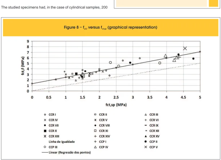
Data presented in Figure 8 comprise the set of results obtained in several studies and used in this analysis, as mentioned above, and the regression equation between points (with R2 = 0.88) is:
(15)
]
[
30
,1
.
16
,
1
,,
f
MPa
f
ct f=
ct sp+
862 IBRACON Structures and Materials Journal • 2013 • vol. 6 • nº 6
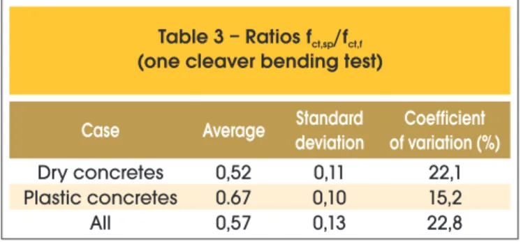
Thus, it can be observed that the set of dry and plastic concretes considered herein, statistically treated in terms of its tensile strengths (bending and indirect), results in irrelevant change of the previously established relationship by Hammitt [28] for plastic concretes, and it is noteworthy to highlight that the results pre-sented refer to bending tensile strength measured with a single cleaver testing. This study covers a broader range of strength for the generalization of the relationship sought between strengths. Note that all the points are above the line of equality between the parameters (45o) that means that the bending tensile stress on a cleaver have always resulted higher than the indirect tensile strength. In Table 2, there is a numerical comparison between 14 and 15 equations, which allows ensuring the use of both in case of dry concretes, at least in the range between 0.5 and 2.5 MPa of ultimate strength, when there is no important percent-ages variations between both. Table 3 shows direct relationships between values of indirect tensile strength and bending tensile strength to the same concretes, dry and plastic. It is observed that the dry concrete, naturally less mortared and more porous, has higher dispersion in results. The standard deviation obtained must be still considered high for molded samples in laboratory, which clearly indicates that the correlations should be cautiously considered when estimating bending tensile strength by diam-etral compression testing.
5. Conclusions
The issues about stress ield distribution on concretes were ad -dressed, because they have great interest in the ield of plain concrete paving, as well as for the use of concrete foundations loors with asphaltic coatings. These stress ields, very different to the bending tensile test and indirect tensile test by diametral compression, ultimately result in values of tensile strength of the concrete different among themselves and hard to be correlated, given that the Brazilian test, more simple in practical and under -standable terms on the stresses distribution, is not usual for tech-nological control or mix proportioning of concretes for pavements. The tests presented in this article, which were carried out with dry compacted and plastic vibrated concrete, with materials that took very different inputs with each other, as slag or rub-bers as sand particle fractions, recycled aggregates from con-struction and demolition waste, milled asphalt mixtures, high-performance and conventional concretes, in all cases, never revealed to the specimens, indirect tensile strength superior to
the bending tensile strength. A relationship was also observed between both strengths four decades ago for plastic concretes, and a correlation was proposed for a broader range of stud-ied concrete, validating the previous equation for dry concrete, of great interest for asphalt pavement bases and for concrete pavements (as the roller compacted concretes by and cement treated crushed stones).
The determination of strength by diametral compression, al-though it is non-standard as a mix proportioning and quality control parameter, can be gradually used for determination of concrete strength achieved at low ages (like a “thermometer” that can be expected from long-term strength), but especially for control of the inished concrete in track, given that the extrac -tion of cylindrical specimens is very simple and has a destruc-tive character much less relevant than the extraction of samples for making prismatic specimens in lab. It is suggested, in this case, to experimentally establish for each work a relationship between fct,f and fct,sp, avoiding the use of general correlations obtained from the previous technical literature, or even from earlier work records. Within the same work, there are possi-bilities, with systematic studies and constancy of materials, to reach the estimated models of good quality, as proposed by the study presented.
The continuous use of the technique of indirect tensile test by diametral compression can bring new lights in the future on how to take better advantage of a simple test preparation, whether from the point of view of molding or extraction, as well as con-sidering the same laboratory apparatus for its performance. On the other hand, the uniform ield of tensile stress distributions provides an important potential to the study, with less disper-sion of results, of the modulus of elasticity of concrete in tensile, of great interest for various paving works with plain concrete or cemented materials for pavements bases.
The literature review points out that the strength measurements are affected by the scale effect, i.e. the size of the specimens. The studies make it clear that different formats of specimens and distinct tests impose stress ields for each case that implies tensile strength also unequal to the same concrete. The discussions pre-sented clearly indicate that the concrete strength in the form of a working slab in a plane stresses state, which is the real world, can be quite different, being higher than the tensile strength measured by tests in a nearly uni-directional stresses state. Tensile strength in diametral compression tests is lower than those measured in bending beams, and the latter test is conservative with respect to the strength in plane stresses state, as seen in theory. What gives us the idea that there is still an open ield to better specify concrete mix proportion and control criteria for pavements.
Table 2 – Deviation between Hammitt
equation (1971) and current study
f
ct,sp(MPa)
f (MPa)
ct,fHAMMITT (1971)
f (MPa)
ct,f(current)
D
f (%)
ct,f0.5
1.0
1.5
2.0
2.5
1.99
2.5
3.01
3.52
4.03
1.88
2.46
3.04
3.62
4.2
5.53
1.60
-1.00
-2.84
-4.22
Table 3 – Ratios f /f
ct,sp ct,f(one cleaver bending test)
Case
Average
Standard
deviation
of variation (%)
Coefficient
Dry concretes
Plastic concretes
All
0,52
0.67
0,57
0,11
0,10
0,13
[17] ASSOCIAÇÃO BRASILEIRA DE NORMAS TÉCNICAS. Concreto-Determinação da resistência à tração na lexão em corpos-de-prova prismáticos. ABNT NBR 12142, 1991, Rio de Janeiro.
[18] AMERICAN SOCIETY FOR TESTING AND MATERIALS. Standard Test Method for Flexural Strength of Concrete (using simple beam with third-point loading). ASTM standard C78-08, 2008, West Conshohocken. [19] CERVO, T.C. Estudo da resistência à Fadiga de
Concretos de Cimento Portland para Pavimentação. Tese (Doutorado), EPUSP, 2005.
[20] BAZANT, Z. P.; NOVAK, D. Proposal for standard test of modulus of rupture of concrete with its size dependence. ACI Materials Journal, v.98, 2001, pp.79-87. [21] KANG, S-T; PARK, J-J; RYU, G-S; KOH, G-T; KIM,
S.W. Comparison of tensile strength with different test methods in ultra-high strength steel-iber reinforced concrete. Key Materials Engineering, v. 417-418, 2010, pp.649-652.
[22] PINTO, P.C.; BALBO, J.T.; SACHET, T; MUGAYAR, A.N.; Albuquerque, M.C.F. (2009) Avaliação de efeitos da substituição da areia por borracha moída ina de pneus em concretos compactados. Anais do 51º. Congresso Brasileiro do Concreto (Cdrom), Instituto Brasileiro do Concreto, Curitiba.
[23] SACHET, T; BALBO, J.T.; PINTO, P.C.; MUGAYAR, A.N.; Albuquerque, M.C.F. Incorporação de fresado asfáltico em concreto compactado com rolo. Anais do 51º. Congresso Brasileiro do Concreto (Cdrom), Instituto Brasileiro do Concreto, 2009, Curitiba. [24] MUGAYAR, A.N.; BALBO, J.T.; PINTO, P.C.;
SACHET, T; Albuquerque, M.C.F. Avaliação de efeitos da substituição da areia por borracha moída ina de pneus em concretos compactados. Anais do 51º. Congresso Brasileiro do Concreto (Cdrom), Instituto Brasileiro do Concreto, 2009, Curitiba. [25] TSENG, E. ; BALBO, J. T. . Concrete Pavement
Recycling for Use as Aggregates in New Concrete for Pavements - Mario Covas Metropolitan Road Ring case. In: 2nd International Conference on Best Practices for Concrete Pavements, 2011, IBRACON, Cdrom, Florianópolis.
[26] AMERICAN SOCIETY FOR TESTING AND MATERIALS. Standard Test Method for Splitting Tensile Strength of Cylindrical Concrete Specimens. ASTM standard C496M-04, 2004, Philadelphia.
[27] AMERICAN SOCIETY FOR TESTING AND MATERIALS.
Standard Test Method for Flexural Strength of
Concrete (Using Simple Beam With Center-Point Loading). ASTM standard C293-08, 2008, Philadelphia.
[28] HAMMITT, G.M. II. Concrete strength relationships. US Army Corps of Engineers, Waterways Experiment Station, 1971, Vicksburg.
6. Acknoledgements
The author is grateful to the Brazilian Council for the Development of Science and Technology (CNPq) whom supported the research under the project 473498/2006-5.
7. References
[01] TROXELL, G.E.; DAVIS, H.E.; KELLY, J.W. Composition and properties of concrete. Second edition,
McGraw-Hill, 1968, New York.
[02] BALBO, J.T. Estudo das propriedades mecânicas das misturas de brita e cimento e sua aplicação aos pavimentos semirrígidos. Tese (Doutorado), EPUSP, 1993.
[03] BAZANT, Z.P.; CEDOLIN, L. Whuy direct tension specimens lex and break at midlength. Proceedings: First International Conference on Fracture Mechanics of Concrete Structures, Elsevier Applied Science,
Colorado, 1993.
[04] METHA, P.K.; MONTEIRO, P.J.M. Concreto – microestrutura, propriedades e materiais. Instituto Brasileiro do Concreto, 2008, São Paulo.
[05] NEWMAN, D. A.; BENNETT, D. G. The Effect of Specimen Size and Stress Rate for the Brazilian Test - A Statistical Analysis. Rock Mechanics and Rock Engineering 23, 1990, p. 123-134.
[06] BALBO, J.T. Pavimentos de concreto. Oicina de Textos, São Paulo, 2009.
[07] CARNEIRO, F.B.L. Une novelle methode d’essai pour determiner la Resistance à la traction du beton. Reunion dês Laboratoires d’Essai de Materiaux, 1947, Paris.
[08] ASSOCIAÇÃO BRASILEIRA DE NORMAS TÉCNICAS.
Argamassa e concreto - determinação da resistência
à tração por compressão diametral de corpos-de-prova cilíndricos. ABNT NBR 7222, 1994, Rio de Janeiro. [09] FUSCO, P.B. Estruturas de concreto – Fundamentos
do projeto estrutural. McGraw-Hill, 1976, São Paulo. [10] PROVETI, J.R.C.; MICHOT, G. The Brazilian test: a
tool for measuring the toughness of a material and its brittle to ductile transition. Int. J. of Fracture Vol. 139-3, 2006, p. 455 .
[11] TIMOSHENKO, S. Theory of Elasticity. McGraw-Hill Book Company, 1934, New York.
[12] FROCHT, M. M. Photoelasticity. 3rd printing, John Wiley & Sons, 1961, New York.
[13] DURELLI, A.J.; PARKS, V.J. Moiré Analysis of Strain. Prentice-Hall, 1970, Englewood Cliffs.
[14] KRISHNAYYA, A.V.G; EISENSTEIN, Z. BRAZILIAN TENSILEB TEST FOR SOILS: REPLY. Canadian Geotechnical Journal, v.12, 1975, 544.
[15] AYDIN, A.; BASU, A. The use of Brazilian test as quantitative measure of rock weathering. Rock Mechanics and Rock Engineering, 39 (1), 2006, pp.77-85.
![Figure 1 – Fringes for tensile strain fields (left) and compression strain fields (right) in diametral compression test (extracted from: Durelli e Parks [13])](https://thumb-eu.123doks.com/thumbv2/123dok_br/18860124.417782/3.892.69.832.194.549/figure-fringes-tensile-compression-diametral-compression-extracted-durelli.webp)