João Luís Camacho Baptista Figueira
DOUTORAMENTO EM QUÍMICA
Carbon-rich Bridging Systems
A systematic study
TESE DE DOUTORAMENTO
CO-ORIENTAÇÃO
Kari Tapani Rissanen
ORIENTAÇÃO
João Manuel Cunha Rodrigues
João Luís Camacho Baptista Figueira
DOUTORAMENTO EM QUÍMICA
Carbon-rich Bridging Systems
A systematic study
iii
The work presented in this dissertation was
performed in the Molecular Materials Research Group
of the Madeira Chemistry Research Centre (CQM),
University of Madeira, and in the Department of
Chemistry, Nanoscience Centre, University of
Jyväskylä, Finland. It was financially supported by the
Fundação para a Ciência e a Tecnologia through the
PhD grant SFRH/BD/29325/2006, and partly by the
research projects POCTI/CTM/41495/2001,
PTDC/CTM/098451/2008, and CQM Strategic Plan,
v
However, a good laugh is a mighty good thing, and rather too scarce a good thing; the more's
the pity. So, if any one man, in his own proper person, afford stuff for a good joke to anybody, let
him not be backward, but let him cheerfully allow himself to spend and be spent in that way. And
the man that has anything bountifully laughable about him, be sure there is more in that man
than you perhaps think for.
vii
Acknowledgements
You don't have to be a "person of influence" to be influential. In fact, the most influential people
in my life are probably not even aware of the things they've taught me.
– Scott Adams
I acknowledge my supervisors and senior collaborators:
To Prof. João Rodrigues, for accepting me in his group since my licentiate degree and continued supervision and guidance throughout my still brief scientific career. Prof. João has molded my professional character.
To Acad. Prof. Kari Rissanen, for receiving me year after year in his group, and treating me as one of his “regular” students. For taking the time to personally teach me XRD.
To Prof. José Carlos Mesquita (University of Madeira, Portugal), for performing the cyclic voltammetry tests on the compounds and the resulting data compilation and reports.
To Mr. Reijo Kaupinen (University of Jyväskylä, Finland), for his continued NMR assistance and teaching and for being one of the best persons I know, always ready with a smile to help anyone.
To Ms. Mirja Lahtiperä (University of Jyväskylä, Finland), for introduction and general operation of the ESI-TOF spectrometer and for the wonderful and priceless insights on the acquisition of organometallic samples.
To Dr. Arto Valkonen (University of Jyväskylä, Finland), for helping me finish some crystal structures preparation for the thesis.
To Prof. Fernando Lahoz (University of La Laguna, Spain), for the solid state fluorescence measurements of the compounds I have prepared.
To Dr. César Fernandes (LREC – Laboratório Regional de Engenharia Civil, Funchal, Portugal), for letting me use LREC’s ATR-FTIR to finish some characterization data.
To the CCCEE (Centro de Competência de Ciências Exatas e da Engenharia, University of Madeira) lab technicians, Ms. Ana Paula Tentem and Mrs. Ana Paula Andrade, for their continued lab support throughout all my lab work.
viii
I acknowledge my laboratory colleagues and friends:
To Manuel Jardim, for the chemistry discussions, for working together in the matters of laboratory management and for being a good friend.
To all my friends, Micaela Fernandes, Rita Andrade, Lilia Camacho, Dr. Carla S. Alves, Dr. Luís Santos, Nilsa Oliveira, Rita Castro, Mara Gonçalves, Cláudia Camacho, Dr. Alireza Nouri, that helped one way or the other with support or simply good mood.
To Dr. Ondřej Jurček, one of my best friends, for helping me time and again to settle
and socialize in the busy winter life of Finland and to the rest of all the friends I met on my trips to Jyväskylä and that made my stays several fold better: Asela Manatunga, Chandan Giri, Dr .Nonappa, Dr. Ngong Kodiah Beyeh, Virpi Noponen, Dr. Satu Ikonen, Hana Svobodova, Dr. Jens Bunzen and Jenni Ranta.
To Dr. Visvaldas Kairys, for all the help with GAMESS and its steep learning curve even though I was unable to produce any fitting results for this dissertation. It is still a learning process at this point.
To Ana Cristina Olival, for some melting point measurements and a helpful hand around the lab during her internship.
I acknowledge my family
To my wife-to-be, Sandra Gouveia, for her unyielding support, uplifting and contagious cheerfulness. I have a world of debt to her.
To my parents, Alberto and Fernanda Figueira, for never doubting me and supporting my ambitions and projects no matter what.
I acknowledge the financial support
To FCT (Fundação para a Ciência e a Tecnologia) for the Ph.D. grant SFRH/BD/29325/2006 for this work, research projects POCTI/CTM/41495/2001, PTDC/CTM/098451/2008, and CQM Strategic Plan, PEst-OE/QUI/UI0674/2011.
ix Network (PTNMR-REDE/1517/RMN/2005-POCI2010/FEDER) for providing equipment essential to this work.
To the Instituto de Emprego da Madeira, for a professional internship that supported the final year of work.
xi
Resumo
Nesta dissertação discute-se os resultados obtidos na preparação de compostos candidatos a serem usados como fios moleculares. Estes compostos utilizam pontes orgânicas derivadas do 1,4-dietinilbenzeno com cadeias laterais alcoxil, assim como terminações compostas por complexos de paládio e ruténio. Os compostos foram caracterizados utilizando as técnicas espectroscópicas habituais tais como RMN 1H, 13C e 31P, MS, FTIR e UV-Vis, bem como voltametria cíclica que permitiu classifica-los de acordo com o sistema Robin–Day e determinar o efeito das pontes e comprimentos das cadeias laterais no transporte de eletrões.
Os ligandos derivados de 1,4-dietinilbenzeno foram preparados através de vias de síntese baseadas, principalmente, em acoplamentos catalisados por paládio (Acoplamento cruzado de Sonogashira). Assim sendo, foi preparada uma família de compostos do tipo 1,4-dietinilbenzeno com um anel e diferentes comprimentos da cadeia lateral alcoxil (OCH3, OC2H5,
OC7H15).
Os complexos binucleares de ruténio revelaram comunicação eletrónica entre os centros metálicos apenas quando os ligandos mais curtos são usados, enquanto os mais longos apresentaram, nos estudos de voltametria cíclica, apenas um par redox característico. Nos resultados de voltametria cíclica observaram-se dois processos irreversíveis de uma onda para os complexos dinucleares de paládio o que faz com que estes complexos possam ser considerados como isoladores moleculares.
O decaimento da fluorescência dos compostos sintetizados (ligandos e complexos) revela um padrão em que os tempos de decaimento decrescem com a coordenação aos complexos metálicos. Tal pode dever-se à redistribuição da carga dos ligandos aquando da coordenação conduzindo a percursos de relaxamento não radiativos. No decorrer do trabalho foram determinadas as estruturas de raios-X, de dois novos ligados e de um composto com paládio.
Verificou-se que as cadeias laterais, quando presentes, melhoram as características de deslocalização de carga dos complexos. Contudo, o efeito introduzido pelas cadeias laterais mais longas é quase negligenciável.
xiii
Abstract
This dissertation presents and discusses the preparation of molecular wires (MW) candidates that would then be probed for electron transfer properties. These wires are bridged by 1,4-diethynylbenzene derivatives with alkoxy side chains with palladium and ruthenium metal complex termini. Characterization of these compounds was performed by usual spectroscopic techniques like 1H, 13C{1H} and 31P{1H} NMR, MS, FTIR and UV-Vis as well as by cyclic voltammetry which allowed classifying the candidates in the Robin–Day system and determination of bridges side chain and length effects on electronic transport.
Preparation of the 1,4-diethynylbenzene derivatives was done with synthetic pathways that relied heavily in palladium catalyzed cross-couplings (Sonogashira). A family of single ringed 1,4-diethynylbenzene ligands with different length alkoxy side chains (OCH3, OC2H5,
OC7H15) was thus prepared allowing for the influence of these ring decorations to be assessed.
The ruthenium binuclear rods showed communication between metal centres only when the shorter ligands were used whereas the longer Ru complexes showed only one redox pair in CV studies which is in agreement to non-communicating metal centres.
Cyclic voltammetry studies show irreversible one wave processes for palladium dinuclear complexes, making these rods function as molecular insulators.
Fluorescence decay studies performed on the prepared compounds (ligands and complexes) show a pattern of decreasing decay times upon coordination to the metal centres which can due to ligand charge redistribution upon coordination leading to non-radiative relaxation paths.
Regarding the X-ray structures, two new ligand related structures were obtained as well as new structure for a palladium rod.
The effect of the side chains was observed to be important to the wires’ electronic properties when comparing with the analogs without a side chain. The effect brought by longer chains is nevertheless almost negligible.
xv
List of publications
Articles
Related to this thesis
6-“Synthesis, characterization, X-ray structures, substituent effects and solid-state
photoluminescence studies of phenylene ethynylene based dinuclear palladium (II) rods with alkoxy side chains”, João Figueira, Wojciech Czardybon, José Carlos Mesquita, João Rodrigues, Fernando Lahoz, Luca Russo, Arto Valkonen and Kari Rissanen. Under preparation.
5-“A convenient route for the preparation of the monohydride catalyst trans-[RuCl(H)(dppe)2]
(dppe = Ph2PCH2CH2PPh2): Improved Synthesis and Crystal Structure”,
João Figueira, Manuel G. Jardim, João Rodrigues, Arto Valkonen, Kari Rissanen, Inorg. Chem.
Comm., 2013, 29, 123-127.
4-“Three 2,5-dialkoxy-1,4-diethynylbenzene derivatives”,
João Figueira, João Rodrigues, Kari Rissanen, Acta Cryst., 2008, C64, o33-o36.
3-“trans-[bis(diphenylphosphino)methane-κ2P,P']dichlororuthenium(II)dichloromethane
disolvate”,
João Figueira, João Rodrigues, Kari Rissanen, Acta Cryst., 2006, E62, m3594-m3596.
2-"cis-Aquabis[bis(diphenylphosphino)ethane- қ2P,P´]-chlororuthenium(II) hexafluorophosphate
1.5-dichloromethane 0.5-water solvate",
Luca Russo, João Figueira, João Rodrigues and Kari Rissanen, Acta Cryst., 2006, E62,
m699-m701.
1-"cis-[bis(diphenylphosphino)ethane- қ 2P,P´]dichlororuthenium(II)dichlomethane disolvate",
Luca Russo, João Figueira, João Rodrigues and Kari Rissanen, Acta Cryst., 2006, E62,
xvi
Other work
3-“Poly(alkylidenamines) dendrimers as scaffolds for the preparation of low-generation
ruthenium based metallodendrimers”,
João Rodrigues, Manuel G. Jardim, João Figueira, Marisol Gouveia, Helena Tomás, Kari Rissanen, New J. Chem., 2011, 35, 1938-1943.
2- “4,4'-[Thiophene-2,5-diylbis(ethyne-2,1-diyl)]dibenzonitrile”,
João Figueira, João Rodrigues, Viatslav Vertlib, Kalle Nättinen, Kari Rissanen; Acta Cryst.,
2008, E64, o765-o766.
1-“A Trinuclear Aqua Cyano-bridged Ruthenium Complex [((η5-C5H5)(PPh3)2Ru(μ
-CN))2RuCl2(PPh3)(H2O)][PF6]: Synthesis, Characterization and Crystal Structure",
Viatcheslav Vertlib, João Figueira, José Mesquita, João Rodrigues, Kalle Nättinen and Kari Rissanen, Eur. J. Inorg. Chem., 2007, 13, 1920-1924.
Oral presentations
Related to this thesis
2012(2)
“Organic-inorganic hybrid molecular/semiconductor waveguides based on oligo(phenylene ethynylene)s derivatives”,
João Figueira, Nilsa Oliveira, Fei Hui, José Carlos Mesquita, João Rodrigues, Kari Rissanen, Workshop nano12 – Shaping the future –, Academia das Ciências de Lisboa, Portugal, 18th October, 2012.
"Oligo(phenyleneethynylene)derivatives for application as organic-inorganic hybrid molecular/semiconductor waveguides",
xvii 2011(1)
“Progress on the synthesis and characterization of dinuclear Pd and Ru rods for the preparation of organometallic molecular wires”.
João Figueira, José Carlos Mesquita, João Rodrigues, Kari Rissanen, 6th Material Group Meeting/CQM, University
of Madeira, Funchal, Portugal, 28th January, 2011.
2010(3)
“Preparation and characterization of Ruthenium and Palladium dinuclear Rods as potential molecular wires”,
João Figueira, José Mesquita, João Rodrigues, Kari Rissanen, 7th Supraphone meeting, Maria Laach, Germany,
April 29th to May 1st 2010.
“Ruthenium and palladium dinuclear OPE and OTE rods for nanoelectronic applications”,
João Figueira, José Carlos Mesquita, João Rodrigues, Kari Rissanen, 2nd Portuguese Young Chemists Meeting,
Universidade de Aveiro, Portugal, April 21-23rd, OC-19, 2010.
“Synthesis and characterization of dinuclear Pd and Ru rods for the preparation of organometallic molecular wires”, João Figueira, José Carlos Mesquita, João Rodrigues, Kari Rissanen, 5th Material Group Meeting/CQM, University
of Madeira, Funchal, Portugal, 29th January, 2010.
2009(2)
“Preparation of Ruthenium and Palladium Dinuclear OTEs and OPEs Rods for Application as Molecular Wires”, João Figueira, José Carlos Mesquita, João Rodrigues, Kari Rissanen, 4th Material Group Meeting/CQM, Funchal,
Portugal, 30th of January, 2009 (Flash presentation).
“Ruthenium and Palladium OPE and OTE bridged rods for Application as Molecular Wires“,
João Figueira, José Mesquita, João Rodrigues, Kari Rissanen, XVIII EuCheMS Conference on Organometallic Chemistry, Gutenberg, Sweden, 22-25th June, O-26, 2009.
2008(5)
"Molecular Wires and Metallodendrimers - a “nano” introduction",
João Rodrigues, Helena Tomás, José Carlos Mesquita, João Figueira, Manuel Jardim, Swarup Maiti, Workshop on Coordination and Organometallic Chemistry Towards New Materials, University of Madeira, Funchal, Portugal, 3rd
of December 2008.
"Pd and Ru complexes with OPE and OTE bridging ligands for nanoelectronic applications",
xviii
“Progress on the preparation of Binuclear Pd and Ru complexes based on OPE and OTE bridging ligands for nanoelectronic applications”,
João Figueira, José Mesquita, João Rodrigues, Kari Rissanen, CQM Materials Line Meeting, 29th of October 2008,
Funchal/Portugal (Private communication).
“Binuclear Pd and Ru based on OPE and OTE bridging ligands for nanolectronic applications”,
João Figueira, João Figueira, Kari Rissanen, Nanoschool 2008, University of Madeira, 13-17th October 2008.
“Novel Dinuclear Oligo(thienyleneethynylene)s Bridged Ruthenium Rods”,
João Figueira, João Rodrigues, Kari Rissanen, 3rd Material Group Meeting/CQM, Funchal, Portugal, January, 2008
(Flash presentation).
2007(1)
“Novel Polarised Molecular Wires Based on Transition Metal Complexes of di(4-pyridyl)heterocycles Spacers Bridging Ligands”
João Figueira, Viatcheslav Vertilib, João Rodrigues and Kari Rissanen, 2nd Material Group Meeting/CQM, Funchal,
Portugal, January, 2007 (Flash presentation).
2006(1)
"Organometallic Materials for Photonics and Molecular Electronics Nanoscale Devices",
João Rodrigues, Zsolt Csok, Wojciech Czardybon, João Figueira, Manuel Jardim and José Mesquita, Fourteen International Conference on Composites/Nano Engineering (ICCE-14), Boulder, USA, 2-8th July, 2006.
Other work
2012(2)
"Ruthenium poly(alkylidenamine) nitrile dendrimers - a new family of biometallodendrimers”, João Rodrigues, Manuel Jardim, Marisol Gouveia, João Figueira, Helena Tomás, and Kari Rissanen
XXV International Conference on Organometallic Chemistry (XXV ICOMC), September 2-7, Lisbon, OCS3.6, page 42, 2012.
“Low-generation ruthenium based metallodendrimers for biomedical applications”,
João Rodrigues, Manuel Jardim, João Figueira, Marisol Gouveia, Helena Tomás, and Kari Rissanen
3rd International Symposium on Biological Applications of Dendrimers, 5th-8th September, Toledo, Spain, OC5,
xix
Poster presentations
2012(1)
“Preparation and cyclic voltammetry studies of Ru and Pd phenylene ethynylene and thiophenylene ethynylene rods”,
João Figueira, José Carlos Mesquita, Kari. Rissanen, João Rodrigues, XIV Iberic Meeting of Electrochemistry & XVII Meeting of the Portuguese Electrochemical Society, CQM - University of Madeira, Funchal, Portugal, 11-14th of March, PF3 (page 84), 2012.
"Oligo(phenyleneethynylene)derivatives for application as organic-inorganic hybrid molecular/semiconductor waveguides",
Nilsa Oliveira, João Figueira, Fei Hui, João Rodrigues, José Carlos Mesquita, Kari Rissanen, F. Lahoz, XXV International Conference on Organometallic Chemistry (XXV ICOMC), September 2-7, Lisbon, Portugal, PSA, F2.8, page 47 2012.
2011(2)
“Oligo(phenylene ethynylene) bridged RuCl(dppe)2 and PdCl(PEt3)2 rods: synthesis, electrochemistry,
fluorescence and X-ray structures”,
João Figueira, José Carlos Mesquita, Arto Valkonen, Natte Nättinen, Kari. Rissanen, Fernando. Lahoz, João Rodrigues, XXII Encontro Nacional SPQ, University of Minho, Braga, Portugal, 3-6th of July, QI-CP 03, 2011.
“Time resolved fluorescence characterization of oligo(p-phenylene ethynylene) based metallic nanorods”,
Fernando Lahoz, D. López, João Figueira, José Carlos Mesquita, Nilsa Oliveira, João Rodrigues, Arto Valkonen, Natte Nättinen, Kari Rissanen, TNT – Trends in Nanotechnology, Tenerife, Spain, 21-25th of November, 2011.
2010(2)
“Analysis of Organometallic Compounds by Using Electrospray Quadrupole Ion Trap Mass Spectrometry”, Ying Lu, João Figueira, Manuel Jardim, João Rodrigues, 4th Portuguese Mass Spectroscopy Meeting, FCUL, Lisbon, Portugal, 13-15th of December, P01, page 47, 2010.
xx 2009(1)
“A new family of Palladium and Ruthenium binuclear rods for electronic applications”,
João Figueira, João Rodrigues, Wojciech Czardybon, Luca Russo, Kari Rissanen, 8th Conference on Inorganic Chemistry, Curia, Portugal, 16 – 17th of October, page 101, 2009.
2008(3)
“Novel Binuclear Ruthenium Oligo(thiophenyleneethynylene) rods for Nanoeletronic Applications”,
João Figueira, João Rodrigues, Kari Rissanen, 2nd EuCheMS Chemistry Congress, 17-20th of September, Turin,
Italy, page 39, VI-2, Nanomaterials, 2008.
“Single Crystal X-Ray Studies of Several Ruthenium Complexes Used as Starting Materials for Organometallic Nanomaterials”,
João Rodrigues, João Figueira, Luca Russo, Kalle Nätinnen, Kari Rissanen, ICOMC 2008, 13-18th of July 2008,
Rennes, France, page 739, 2008.
“Molecular Materials Based on Organometallic Compounds”,
João Rodrigues, João Figueira, Manuel Jardim, Swarup Maiti, José C. Mesquita, NanoSpain 2008, 14-18th of April,
Braga, Portugal, page 36, 2008.
2007(2)
“New OPE And OTE Ruthenium Metallomolecular Wires”,
João Figueira, José Mesquita, João Rodrigues and Kari Rissanen, 7ª Conferência de Química Inorgânica da Sociedade Portuguesa de Química, Fátima, Portugal, 30th of November to 1st of December 2007.
“New Metallomolecular Wires Based In Oligothiophene Bridging Systems –A Systematic Study”,
xxi
Abbreviations and symbols
Infra-red stretching mode Ac Acetyl or Acyl group (-C(O)CH3)
Ar Aromatic (ring)
ATR Attenuated Total Reflectance
C60 [C60]Fullerene
CMOS Complementary Metal Oxide Semiconductor CNS Creutz, Newton and Sutin
CNT Carbon Nanotube
Cp Cyclopentadienyl (ƞ5-C 5H5)
Cp* Pentamethylcyclopentadienyl (ƞ5-C
5(CH3)5)
CP-AFM Conducting Probe Atomic Force Microscopy CSD Cambridge Structural Database
d doublet (NMR)
dba Dibenzylideneacetone
DBU 1,8-Diazabicyclo[5.4.0]undec-7-ene DFT Density Function Theory
DMBA N,N’-dimethylbenzamidinate DMSO Dimethyl sulfoxide
dppe 1,2-Bis(diphenylphosphino)ethane dppf 1,1'-Bis(diphenylphosphino)ferrocene dppm 1,2-Bis(diphenylphosphino)methane
EFISH Electric Field Induced Second Harmonic Generation
eq Molar equivalent
Eqn. Equation
ESI-TOF Electrospray Ionization – Time Of Flight Et Ethyl (-CH2CH3)
ET Electron-transfer
Fc Ferrocene
FTIR Fourier Transform Infra-Red spectroscopy. HOMO Highest Occupied Molecular Orbital ICT Intervalence Charge Transfer ILCT Inter-Ligand Charge Transfer IMW Insulated Molecular Wires IT Information Technology
Kc Comproportionation constant (Kc= exp (ΔEº F/RT)
LEDs Light-Emitting Diode
LMCT Ligand To Metal Charge Transfer LUMO Lowest Occupied Molecular Orbital m medium (IR) or multiplet (NMR) MeO-DMBA N,N’-dimethyl-3-methoxybenzamidinate MLCT Metal to ligand charge transfer
MV Mixed Valence
NDR Negative differential resistance
NIR Near Infra-Red
xxii
OTTLE Optically Transparent Thin-Layer Electrochemical
Ph Phenyl
PKS Piepho, Krauz and Schatz PPE poly(phenylene ethynelene) PPP poly(p-phenylene) polymers
PT poly(α, α’-thiophene) polymers
q quartet (NMR)
quint quintet (NMR)
r.t. room temperature
Ref. Reference
s singlet (NMR) or strong (IR)
SAM Self-assembled monolayer
Sat. Saturated
STM Scanning Tunneling Microscope
STM-BJ Scanning Tunneling Microscope Break Junctions STS Scanning Tunneling Spectroscopy
t triplet (NMR)
Tacn N,N’,N’’-trimethyl-1,4,7-triazacyclononane TBAF Tetrabuthylamonium Fluoride
t-Bu tert-butyl
TEA Triethylamine
TMEDA N,N,N',N'-tetramethylethane-1,2-diamine
TMSA Trimethylsilylacetylene Tpy 2,2';6',2"-terpyridine
w weak (IR)
xxiii
Contents
Acknowledgements ... vii Resumo ...xi Abstract... xiii List of publications ... xv Articles ... xv
Related to this thesis ... xv Other work ... xvi
Oral presentations ... xvi
Related to this thesis ... xvi Other work ... xviii
Poster presentations ... xix Abbreviations and symbols... xxi Contents ... xxiii Figure Index ... xxix Scheme Index ... xxxix Table index ... xli
Chapter I – Introduction ... 1
Introduction ... 3 I.1. Molecular electronics ... 3 I.2. Molecular wires ... 7 I.3. Organic molecular wires ... 9
I.3.1. Oligo(2,5-thiophene ethynylene)s ... 9 I.3.2. Oligo(1,4-phenylene ethynylene) ... 12 I.3.3. Oligo(1,4-phenylene vinylene)s ... 13 I.3.4. Aromatic ladder oligomers ... 13 I.3.5. Oligophenylenes ... 14 I.3.6. Carbon nanotubes ... 14 I.3.7. Graphene ... 15
I.4. Metallomolecular wires ... 16 I.5. Transport and classification of homo binuclear organometallic complexes ... 19
I.6.1. Binuclear 1,4-diethynylbenzene derivatives and non-innocent ligands in Ru systems ... 26
xxiv
I.6.1. Metalocumulenic systems ... 31 I.6.2. Binuclear polyalkynyl bridged systems ... 34 I.6.3. Mixed systems ... 40 I.6.4. Other binuclear systems ... 42 I.6.5. Photonic molecular wires ... 50
I.7. Side chains and decorations ... 54 I.8. Alligator clip molecules... 59 I.9. Testing of molecular wire candidates ... 62 I.10. Binuclear palladium and platinum alkynyl rods ... 66 I.11. Luminescence of binuclear systems ... 71 I.12. Synthesis of the wires, general review ... 75
I.12.1. Ligand synthesis ... 75 I.12.2. Binuclear ruthenium rods synthesis ... 79 I.12.3. Binuclear palladium rods synthesis ... 81
Chapter II – Results and Discussion... 83
II.1. Synthesis of 1,4-diethynylbenzene and 2,5-thiopene derivatives for use as bridging ligands ... 85 II.2. Synthesis of the binuclear palladium rods bridged by 1,4-diethynylbenzene derivatives ... 91 II.3. Synthesis of the binuclear ruthenium rods bridged by 1,4-diethynyl and 2,5-thiophene derivatives ... 93
II.3.1. 1,4-diethynylbenzene derivatives bridged rods... 93 II.3.2. Thiophenylene ethynylene based Rods ... 98
II.4. Preparation of the “alligator clip” molecules and its coordination to a ruthenium rod ... 99 II.5. Ruthenium mono hydrido complex ... 102 II.6. UV-Vis Studies ... 106
II.6.1. Free ligands ... 106 II.6.2. Palladium rods ... 108 II.6.3. Ruthenium rods ... 112
II.7. Cyclic Voltammetry Studies ... 115 II.8. NMR Studies ... 120 II.9. FTIR Studies ... 123 II.10. MS Studies ... 126 II.11. Single crystal X-ray diffraction ... 129
xxv II.11.5. cis-[Ru(η2-O2CCH3)(dppe)2] (37) ... 136
II.11.6. Palladium phenylene ethynylene rod (21b). ... 137
II.12. Fluorescence decay studies ... 139
Chapter III – Conclusions and Future Perspectives ... 143
Chapter IV – Experimental Details and Characterization ... 149
IV.1. General remarks... 151 IV.2. Preparation and characterization of the 1,4-diethynylbenzene and the 2,5-thiophene derivatives ... 152
IV.2.1. 1,4-diethynylbenzene, 5a ... 152 IV.2.2. 1,4-dimethoxy-2,5-diethynylbenzene, 5b ... 153 IV.2.3. 1,4-diethoxy-2,5-diethynylbenzene, 5c ... 155 IV.2.4. 1,4-diheptoxy-2,5-diethynylbenzene, 5d ... 156 IV.2.5. 1,4-dimethoxy-2,5-bis((4-ethynylphenyl)ethynyl)benzene, 10a... 158 IV.2.6. 1,4-diethoxy-2,5-bis((4-ethynylphenyl)ethynyl)benzene, 10b ... 160 IV.2.7. 2,5-bis(4-ethynylphenyl)thiophene, 14b ... 163 IV.2.8. 2,5-bis((4-ethynylphenyl)ethynyl)thiophene, 18b ... 164
IV.3. Preparation and characterization of the palladium rods bridged with 1,4-diethynylbenzene derivatives. .... 166
IV.3.1. 1,4-bis[trans-(ethynyl)Pd(PEt3)2(Cl)]benzene, 20a ... 166
IV.3.2. 1,4-bis[trans-(ethynyl)Pd(PEt3)2(Cl)]-2,5-dimethoxybenzene, 20b ... 168
IV.3.3. 1,4-bis[trans-(ethynyl)Pd(PEt3)2(Cl)]-2,5-diethoxybenzene, 20c ... 170
IV.3.4. 1,4-bis[trans-(ethynyl)Pd(PEt3)2(Cl)]-2,5-dihethoxybenzene, 20d ... 172
IV.3.5. 1,4-bis[trans-((4-ethynylphenyl)ethynylethynyl)Pd(PEt3)2(Cl)]-2,5-dimethoxybenzene, 21a ... 176
IV.3.6. 1,4-bis[trans-((4-ethynylphenyl)ethynylethynyl)Pd(PEt3)2(Cl)]-2,5-diethoxybenzene, 21b ... 178
IV.4. Preparation and characterization of the ruthenium rods bridged with 1,4-diethynylbenzene and 2,5-thiophene derivatives. ... 181
IV.4.1. [Cl(dppe)2Ru–C≡C]2–C6H4, 23a ... 181
IV.4.2. [Cl(dppe)2Ru–C≡C]2–C6H4(OC2H5)2, 23c ... 183
IV.4.3. [Cl(dppe)2Ru–C≡C]2–C6H4(OC7H15)2, 23d ... 185
IV.4.4. [Cl(dppe)2Ru–C≡C–C6H4–C≡C]2–C6H4(OCH3)2, 24a ... 188
IV.4.5. [Cl(dppe)2Ru–C≡C–C6H4–C≡C]2–C6H4(OC2H5)2, 24b ... 190
IV.4.6. [Cl(dppe)2Ru–C≡C–C6H4]2–C5H4S, 27 ... 193
IV.4.7. [Cl(dppe)2Ru–C≡C–C6H4–C≡C]2– C5H4S, 28 ... 195
IV.5. Preparation and characterization of other compounds. ... 198
IV.5.1. trans-[RuCl(H)(dppe)2] (34) ... 198
Annexes ... 203
xxvi
A.1.1. UV-Vis spectroscopy ... 205 A.1.2. FTIR spectroscopy ... 205 A.1.3. NMR spectroscopy ... 205 A.1.4. MS spectroscopy ... 206 A.1.5. Cyclic voltammetry... 206 A.1.6. Single crystal X-ray diffraction ... 206 A.1.7. Fluorescence decay studies ... 207 A.1.8. Elemental Analysis ... 207 A.1.9. Melting point determination ... 207
A.2. General experimental procedures ... 208
A.2.1. Williamson substitution ... 208 A.2.2. Iodination of the 1,4-bis(alkoxy)benzenes ... 208 A.2.3. Bromination of the 1,4-bis(alkoxy)benzenes ... 208 A.2.4. Sonogashira coupling reactions ... 209 A.2.5. Deprotection of “Acetone Protected” ligands ... 209 A.2.6. Deprotection of trimethylsilyl protected ligands... 210 A.2.7. Palladium binuclear complexes. ... 210 A.2.8. Ruthenium phenylene ethynylene binuclear rods. ... 210 A.2.9. Ruthenium thiophenylene ethynylene binuclear rods. ... 211
A.3. Preparation of general starting materials ... 211
A.3.1. RuCl2(DMSO)4 (DMSO = dimethylsulfoxide) ... 211
A.3.2. cis-[RuCl2(dppe)2] ... 212
A.3.3. trans-[RuCl2(dppe)2] ... 212
A.3.4. TlPF6 ... 212
A.3.5. cis-[RuCl(dppe)2][PF6] ... 213
A.4. NMR Studies ... 213
A.4.1. Free ligands ... 213 A.4.2. Palladium rods ... 217 A.4.3. Ruthenium rods ... 220
A.5. MS Studies ... 223
A.5.1. Free ligands ... 223 A.5.2. Palladium rods ... 224 A.5.3. Ruthenium rods ... 227
xxvii 1,4-bis(4-bromo-1-ethynylbenzene)-2,5-diethoxybenzene (8b)... 232 1,4-bis(1,4-diethynylbenzene)-2,5-diethoxybenzene (10a) ... 233
trans-[RuCl(H)(dppe)2] (34) ... 234
cis-[RuCl(η2-O2CCH3)(dppe)2] (37) ... 235
Palladium phenylene ethynylene rod (20b) ... 237 Nitrile terminated thiophenylene ethynylene (38) ... 238
A.8. Fluorescence decay studies ... 240
xxix
Figure Index
Figure 1. Cartoon depicting Moore’s Law across a wide time span.[4] ... 4 Figure 2. 128Å long organic rod (1) prepared by Schumm and co-workers. R = 3-ethylheptyl.[13a] ... 8 Figure 3. An example (2) of a tetrakisporphyrin system (t-Bu is tert-butyl).[15] ... 8
Figure 4. The thiophene oligomers (3) prepared by the group of Otsubo.[23] ... 10 Figure 5. The thiophene-containing arylene-ethynylene/arylene-vinylene co-polymer (4).[26]... 11 Figure 6. The oligo(2,5-thiophene ethynylene) potential wire (5) prepared by the group of Tour (Ac = Acetyl
C(O)CH3).[27-28] ... 11
Figure 7. One of Tour’s OPE wires (Ac = acetyl group, C(O)CH3).[5] ... 12
Figure 8. Organic molecular (7a-b) wires with switching properties.[5] ... 12
Figure 9. One of the OPVs studied by Wasielewski and co-workers.[21b] ... 13
Figure 10. One of the oligo(quinoxaline)s reported by Gourdon.[33] ... 14
Figure 11.An example of the fluorenone based molecular wires prepared by Bryce’s group.[34] ... 14
Figure 12. OPE rod used by Mayor's group bearing a central 2,6-dibenzylamino core-substituted cromophore. a =
phenanthrene π-system; b = OPE rod; c = NDI (N,N-naphtalenediimides) chromophore. Adapted from ref. [36]. ... 15
Figure 13. Cartoon of an atom thick graphene sheet.[38] ... 16
Figure 14. Di-ruthenium systems studied by Mahapatro and co-workers in nanogap molecular junctions. Adapted
from ref. [53e]. ... 20
Figure 15. The ruthenium systems studied by Rigaut and co-workers.[53f, 57] ... 20
Figure 16. Potential energy curves for electron transfer in ligand-bridged binuclear complexes with (a) negligible, (b)
weak (Hab= λ/4) and (c) strong (Hab=3λ/4) electronic coupling. The dotted and solid curves represent the diabatic
and adiabatic surfaces, respectively. Adapted from ref. [63]. ... 25
Figure 17. Example of the systems studied by Klein et al.; [Ru] = [RuCl(dppe)2]+). Adapted from ref. [16]. ... 26
Figure 18. Compounds studied by Rigaut and co-workers (a). IR changes during the first oxidation of 16a (right,
16a → 16a•+, 1,2-C
2H4Cl2/NBu4PF6). Adapted from ref. [66d]. ... 28
Figure 19. The insulating chain bearing systems prepared by the group of Rigaut (a) and the spectroscopic changes
upon oxidation in an OTTLE Cell (1,2-C2H4Cl2, 0.2 M Bu4NPF6) of the system with shorter insulating chain and n =
1 (b). Adapted from ref. [53a]. ... 29
Figure 20. Trimetallic system prepared by the group of Rigaut. Adapted from ref. [46]. ... 30
Figure 21. (Ethynyl)(vinyl)phenylene bridged triruthenium prepared by the Rigaut group. Adapted from ref. [71]. 30
Figure 22. The tetraferrocenyl-[3]-cumulene reported by Bildstein et. al.. Fc = ferrocene. Adapted from ref. [74]. . 32
Figure 23. Binuclear Ru bis(allenylidene) reported by Guesmi et al.. Adapted from ref. [75]. ... 32
Figure 24. Complex used for the study of the effect of increasing number of double bonds (n = 1-4, P = PPh3).
Adapted from ref. [58, 77]. ... 33
xxx
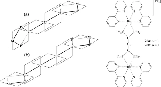
Figure 26. Representation of the π-orbital alignment of the allene-bridged bimetallic complexes (a) and that of the
cumulene-bridged bimetallic complexes (b) as well as the respective complexes (26a-b). Adapted from ref. [80]. .. 34
Figure 27. Series of Cp*Re(NO)(PPh3) terminated binuclear complexes prepared by Gladisz’ group. (n = 2-6, 8, 10).
Adapted from ref. [67b, 83]. ... 35
Figure 28. The polyalkynyl based binuclear wires (28-32). Adpted from ref. [85a] (28), [87] (29), [89] (30 and 31),
[90] (32) and [86] (33). ... 37
Figure 29. The polyalkynyl based binuclear wires (34a-i). Adpted from ref. [52g, 52k] (34a-e) and [53g] (34f-i). .. 38
Figure 30. The polyalkynyl based binuclear wires (35, 36, 37a-c). Adpted from ref. [52f] (35), [52b, 93] (36) and
[52b] (37a-c). ... 39
Figure 31. The polyalkynyl based binuclear (38a-c). Adapted from ref. [94]. ... 39
Figure 32. Example of the type of compounds studied by Chang and co-workers.[95]... 40
Figure 33. (CH)14 binuclear cumulenic complex (41) with semi-reversible two wave processes (CV plot). Adapted
from ref. [96]. ... 41
Figure 34. Binuclear systems reported by Gao and co-workers. Adapted from ref. [98]. ... 41
Figure 35.Ferrocene systems studied in Li’s report. Adapted from ref. [54a]. ... 42
Figure 36. [{FeCp(CO)2}2{1,4-C6H4(CN)2}][PF6]2 binuclear Fe complex studied by Astruc et. al. Adapted from ref.
[99]. ... 42
Figure 37. One of the wires (45a, RuT5) reported by Barbieri and co-workers. Adapted from ref. [101]. ... 43
Figure 38. Trinuclear ethynylthiophene bridged Ru (II) complex. Adapted from ref. [102]. ... 44
Figure 39. Cardan type junction reported by Ruben and co-workers. Adapted from ref. [104]. ... 45
Figure 40.The ruthenium(II) bis(2,2’:6’,2’’-terpyridine) complexes reported by Harriman and co-workers. Adapted
from ref. [105]. ... 45
Figure 41. The trimeric complex prepared by Ying and co-workers. Adapted from ref. [106]. ... 46
Figure 42. Trinuclear complex prepared by Wong and co-workers. Adapted from ref. [107]. ... 46
Figure 43. The Si hybrid wires prepared by the group of Rigaut. Adapted from ref. [66b]. ... 47
Figure 44. The norbornyl based systems reported by Eggers and co-workers. R1= CH2OCH3. Adapted from ref.
[108]. ... 47
Figure 45. Carborane hybrid wires (53a) prepared in the group of Low (central moiety is carborane C2B10H10).
Adapted from ref. [110]. ... 48
Figure 46.“Shish-kebab” type of IMW polymers. Adapted from ref. [112b]. ... 48
Figure 47. Molecular wire candidates studied by Jang and co-workers. Adapted from ref. [113]. ... 49
Figure 48. Insulated molecular wire prepared by Cacialli et al.. Adapted from ref. [114]. ... 49
Figure 49. One of the ZnPorphyrin-Paracyclophane-C60 wires studied by Molina-Ontoria et al.. Adpted from ref.
[122]. ... 52
Figure 50. Porphyrin based molecular photonic wire reported by Lindsey and co-workers. Adapted from ref. [123].
... 52
xxxi
Figure 52. Example of a terpyridyl terminated photonic molecular wire. M = Ru2+, Os2+, n = 1-3. Adapted from ref.
[125a]. ... 54
Figure 53. Phenylene vinylene oligomer with methoxy side chains studied by Meyers and colleagues. Adapted from
ref. [136]. ... 55
Figure 54. A family of binuclear complexes prepared by Akita and co-workers to test the inclusion of side chains.
[Fe] = FeCp*(dppe). Adapted from ref. [82]. ... 55
Figure 55. Study of the effect of the bridging ligand main moiety in FeCp*(dppe) wires. Adapted from ref. [138a].
... 56
Figure 56. OPV wires studied by Detert and Sugiono. Adapted from ref. [32]. ... 56
Figure 57. Polynuclear complex prepared by Fratoddi et al. (65) and Khan et al. (66a-h). Adapted from ref. [140]
and [141] respectively. ... 57
Figure 58. Binuclear ruthenium wires with electron donating and withdrawing side chains. Adapted from ref. [142].
... 58
Figure 59. Binuclear ruthenium complexes with growing alkoxy side chains. Adapted from ref.[143]. ... 58
Figure 60. Binuclear ruthenium complexes with dendritic side chains. Adapted from ref. [144]. ... 59
Figure 61. The most reported types of "alligator clip" molecules found in the literature. Adapted from ref. [8a],
[146], [57, 147] and [57, 147] respectively. ... 60
Figure 62. Direct C–Au molecular junction reported by Chen and co-workers (n = 1-4). Adapted from ref. [154]. . 60
Figure 63. Fullerene C60 terminated wire studied by Bryce and co-workers. Adapted from ref. [155a]. ... 61
Figure 64. Selenium functionalized alligator clips. Adapted from ref. [155b]. ... 61
Figure 65. Pyridine terminated rods. Adapted from ref. [155c]. ... 62
Figure 66. Representative current-distance (I(s)) traces obtained from STM-BJ experiments in UHV (left) and
current histograms constructed from plateau values of about 300 I(s) traces (right) for a 4,4’ -bis(mercaptoalkyl)-biphenyl derivative. Adapted from ref. [163]. ... 65
Figure 67. Heterometallic rods with [Pd(PEt3)2] reported by the group of Gladysz. Adapted from ref. [83b]. ... 67
Figure 68. Molecular PtII rods studied by Mayor and co-workers (76c)[53b] and Shashidhar and co-workers
(77a-e)[176]. Adapted from refs. [53b] and [176]. ... 68
Figure 69. The RuCp(dppf) terminated wires reported by Ge and co-workers. M = Pd or Pt; P_P = dppf
(1,1'-bis(diphenylphosphino)ferrocene).[180] ... 68
Figure 70. The amine terminated wire reported by Jones et al.. Adapted from ref. [181]. ... 69
Figure 71. Palladium diacetylide studied by Koch et al.. Adapted from ref. [183]. ... 70
Figure 72. Fluorenone bridged Pt rod. Adapted from ref. [184]. ... 70
Figure 73. Ruthenium polypyridyl dinuclear complex bridged by Pt and Au moieties. Adapted from ref. [185]. ... 71
Figure 74. Photonic molecular wire prepared as an oligomeric platinum acetylide. n = 2, 3, 6 and 10. Adapted from
ref. [186b]. ... 71
Figure 75. Bisterpyridyl binuclear ruthenium rod bridged by a 1,1’-diethynylferrocene moiety. Adapted from ref.
xxxii
Figure 76. Different bridges studied by Dong et al. using the terpy-Ru2+-terpy-bridge- terpy-Ru2+-terpy as for 84a-b;
R = alkyl chain. Adapted from ref. [187b]. ... 73
Figure 77. Terpyridyl Pt rods studied by Sun and co-workers. Adapted from ref. [187h]. ... 73
Figure 78. Diethynyl carbazole bridged dinuclear Pt and Pd rods. Adapted from ref. [187d]. ... 74
Figure 79. Diethynylphenylene oxidiazole bridged platinum dinuclear rods. Adapted from ref. [187g]. ... 75
Figure 80. Example of Ru(II) di-acetylide preparation as reported by Rigaut and co-workers. Adapted from ref.
[53a]. ... 81
Figure 81. General synthetic method used for the preparation of palladium acetylides. Adapted from ref. [206]. .... 81
Figure 82. Bisalkynyl Pd complex preparation by Fischer et al.. Adapted from ref. [207]. ... 82
Figure 83. General synthetic pathway for the preparation of the mono PE bridging ligands. ... 86
Figure 84. General reaction scheme for the preparation of the single ringed PEs when using the alternative source of
alkynyl, 2-methylbut-3-yn-2-ol. ... 87
Figure 85. General synthetic pathway for the preparation of the tris phenylene ethynylene bridging ligands. ... 89
Figure 86. General synthetic pathway for the preparation of the thiophene based bridging ligands. ... 90
Figure 87. General procedure for the preparation of the [PdCl2(PEt3)2] based binuclear rods. ... 92
Figure 88. General procedure adopted for the preparation of the binuclear PE ruthenium rods. [P] = P(C6H5)2; t
-BuOK = potassium tert-butoxide. ... 93
Figure 89. Preparation of complex 23a following the Dixneuf method (one pot and two step); where X = Na, Tl or
NH4; [P] = P(C6H5)2... 94
Figure 90. 31P{1H} NMR (CD2Cl2, 161 MHz) spectrum of a one-pot attempt to prepare 23c with cis-[RuCl2(dppe)2],
5c, NEt3 and TlPF6. ... 95
Figure 91. General preparation of the thiophene based ruthenium binuclear rods. [P] = P(C6H5)2, i. -78 ºC, t-BuLi,
diethyl ether; ii. CH2Cl2, r.t. ... 98
Figure 92. Preparation of the thiol based “alligator clip”, as reported by Tour.[238] ... 99
Figure 93. Modified preparation of the thiol clip. N(i-Pr)2Et = diisopropylamine; Ac = acyl (CH3C(O)-); N,N-DMA
= N,N -dimethylacetamide; 1,2-DCE = 1,2-dichloroethane; TMSA = trimethilsilylacetylene. ... 100
Figure 94. Coordination of the thiol clip (32) to the tris PE rod (24c). ... 101
Figure 95. 31P{1H} NMR (CDCl3, 161MHz) spectrum of the mixture obtained after several purification attempts of
33. ... 101
Figure 96. Reaction conditions used in the preparation of compound 34. ... 103
Figure 97.31P{1H} NMR (CDCl3, 161 MHz) spectra of three different attempts (experiments (3i-3iii)) to prepare
compound 34 (Method 3). ... 104
Figure 98. Overall mass spectrum of 34 (ESI-TOF, Method 3). ... 106
Figure 99. Electronic spectra of 5a, 5b and 10a in CH2Cl2 at ca. 1x10⁻⁵M. ... 108
Figure 100. Spectra for the palladium rod 20a as well as the respective free ligand (5a) and starting complex (19) in
xxxiii
Figure 101. Spectra for the palladium rod (20b), as well as the respective free ligand (5b) and starting complex (19)
in CH2Cl2 at ca. 1 × 10⁻⁵ M. ... 111
Figure 102. Spectra for the palladium rod (21a) as well as the respective free ligand (10a) and starting complex (19)
in CH2Cl2 at ca. 1 × 10⁻⁵ M for the starting materials and 1 × 10⁻⁶ M for the rod. ... 112
Figure 103. Spectra for the ruthenium rod (23c), as well as the respective free ligand (5c) and the corresponding trans conformer of the starting complex (36) in CH2Cl2 at ca. 6 × 10⁻⁶ M. ... 113
Figure 104. Spectra for a tris-ringed ruthenium rod (24b) as well as the respective free ligand (10b) and the
corresponding conformer of the starting complex (36) in CH2Cl2 at ca. 6 × 10⁻⁶ M. ... 114
Figure 105. Spectra for the ruthenium rods based on the thiophene ligands (27 and 28) as well as the respective free
ligands (14b and 18b) and starting complex (36) in CH2Cl2 at ca. 6 × 10⁻⁶ M for the complexes and 1 × 10⁻⁵ M for
the ligands and starting complex. ... 115
Figure 106. Cyclic voltammograms for the single ringed PE based palladium (20-d) rods with alkoxy side chains at
100 mVs-1 in CH
2Cl2 vs. Ag/AgCl (KCl saturated). ... 116
Figure 107. Cyclic voltammograms for the single ringed PE based ruthenium rods (23c-d) with alkoxy side chains
at 100 mVs-1 in CH
2Cl2 vs. Ag/AgCl (KCl saturated). ... 117
Figure 108. Cyclic voltammogram for thiophene based ruthenium Rods (27 and 28) at 100 mVs-1 in CH2Cl2 vs.
Ag/AgCl (KCl saturated). ... 119
Figure 109. ESI-TOF MS spectrum for palladium rod 20c. ... 128
Figure 110. ESI-TOF MS spectrum for palladium rod 24a. ... 129
Figure 111. ORTEP-3[265] plots of 4c, 5c and 5d (50% probability displacement ellipsoids). ... 130
Figure 112. Packing plot[266] relative to 4c. Only C–H···π interactions are shown. ... 131
Figure 113. Packing plot[266] relative to 5c. The in-plane interactions are shown. ... 131
Figure 114. Packing plot[266] relative to 4c. The C–H···π interactions are shown. ... 132
Figure 115. Perspective ORTEP-3[265] plot of 8b (50% probability displacement ellipsoids). ... 132
Figure 116. Mercury[266] plot of 8b to show short contacts... 133
Figure 117. Perspective ORTEP-3[265] plot of 9a (50% probability displacement ellipsoids). ... 134
Figure 118. Mercury[266] plot of 9c showing short contacts formed between molecules. ... 135
Figure 119. ORTEP-3[265] plot of the trans-[RuCl(H)(dppe)2]·CH2Cl2 in perspective view. The H-atoms, apart from
the hydride, as well as, the solvent molecules are excluded for clarity. Thermal displacement ellipsoids were drawn at 30% probability. ... 135
Figure 120. ORTEP-3[265] plot of cis-[Ru(η2-O2CCH3)(dppe)2][Cl] (37) in perspective view. H atoms, the solvent
molecules and counter-ion (PF6-) are excluded for clarity (30% probability displacement ellipsoids). ... 136
Figure 121. ORTEP-3[265] plot of trans-[PdCl(PEt3)2–C≡C–C6H4–C≡C]2–C6H4(OC2H5)2 (21b). H atoms are
excluded for clarity (30% probability displacement ellipsoids). Right side of the molecules was plotted with disordered atoms. ... 138
Figure 122. Decay of the fluorescence of the free ligands (5a-d, 10a-b) and IRF. ... 140
xxxiv
Figure 124.1H NMR (CDCl3, 400 MHz) spectrum of 5a... 153
Figure 125.1H NMR (CDCl3, 400 MHz) spectrum of 5b. ... 154
Figure 126. Cyclic voltammograms for the single ringed PE free ligands 5a-b. ... 154
Figure 127.1H NMR (CDCl3, 400 MHz) spectrum of 5c. ... 155
Figure 128.1H NMR (CDCl3, 400 MHz) spectrum of 5d. ... 156
Figure 129. Cyclic voltammograms for the single ringed PE free ligands 5c-d. ... 157
Figure 130. UV-Vis spectra of the mono ringed PE ligands (5b-d) bearing side chains in CH2Cl2 at ca. 1x10⁻⁵ M.
... 157
Figure 131. FTIR spectra for the single ringed PE ligands (5b-d). ... 158
Figure 132.1H NMR (CDCl3, 400 MHz) spectrum of 10a... 159
Figure 133. 1H NMR (CDCl3, 400MHz) spectrum of 10b. ... 161
Figure 134. UV-Vis spectra of the tris ringed PE ligands (10a-b) bearing side chains in CH2Cl2 at ca. 1x10⁻⁵ M. . 161
Figure 135. FTIR spectra for the tris ringed PE ligands (10a-b). ... 162
Figure 136. Cyclic voltammograms for the tris ringed PE free ligands (10a-b). ... 162
Figure 137. 1H NMR (CDCl3, 400 MHz) spectrum of 14b. ... 163
Figure 138. 1H NMR (CDCl3, 400 MHz) spectrum of 18b. ... 164
Figure 139.UV-Vis spectra of the thiophene based ligands (14b, 18b) in CH2Cl2 at ca. 1x10⁻⁵ M. ... 165
Figure 140.FTIR spectra for the thiophene based ligands (14b and 18b). ... 165
Figure 141. Cyclic voltammograms for the thiophene based free ligands (14b and 18b). ... 166
Figure 142. 1H NMR (CDCl3, 400 MHz) spectrum of 20a. ... 167
Figure 143. 31P{1H} NMR (CDCl3, 161 MHz) spectrum of 20a. ... 168
Figure 144. 1H NMR (CDCl3, 400 MHz) spectrum of 20b. ... 169
Figure 145. 31P{1H} NMR (CDCl3, 161 MHz) spectrum of 20b using H3PO4 (85% aq.) as external reference. ... 170
Figure 146. 1H NMR (CDCl3, 400 MHz) spectrum of 20c. ... 171
Figure 147. 31P{1H} NMR (CDCl3, 161 MHz) spectrum of 20c using H3PO4 (85% aq.) as external reference. ... 172
Figure 148. 1H NMR (CDCl3, 400 MHz) spectrum of 20d. ... 173
Figure 149. 31P{1H} NMR (CDCl3, 161 MHz) spectrum of 20d. ... 174
Figure 150.UV-Vis spectra of the single ringed PE based palladium binuclear rods (20b-d) bearing side chains in
CH2Cl2 at ca. 1x10⁻⁵ M. ... 174
Figure 151.FTIR spectra for the single ringed PE based palladium Rods (20a-d). ... 175 Figure 152. Cyclic voltammograms for Pd rods bridged by the shorter ligands (20b-d). ... 175
Figure 153. 1H NMR (CDCl3, 400 MHz) spectrum of 21a. ... 177
Figure 154. 31P{1H} NMR (CDCl3, 161 MHz) spectrum of 21a. ... 177
Figure 155. 1H NMR (CDCl3, 400 MHz) spectrum of 21b. ... 179
Figure 156. 31P{1H} NMR (CDCl3, 161 MHz) spectrum of 21b. ... 179
Figure 157. UV-Vis spectra of the tris ringed PE based palladium binuclear rods (21a-b) bearing side chains in
xxxv
Figure 158. FTIR spectra for the tris ringed PE based palladium Rods (21a-b). ... 180
Figure 159. Cyclic voltammograms for Pd rods bridged by the longer ligands (21a-b). ... 181
Figure 160. 31P{1H} NMR (CDCl3, 161 MHz) spectrum of 23a. ... 182
Figure 161. 1H NMR(CDCl3, 400 MHz) spectrum of 23c. ... 184
Figure 162. 31P{1H} NMR(CDCl3, 161 MHz) spectrum of 23c... 184
Figure 163. 1H NMR(CDCl3, 400 MHz) spectrum of 23d. ... 186
Figure 164. 31P{1H} NMR(CDCl3, 161 MHz) spectrum of 23d. ... 186
Figure 165. UV-Vis spectra of the single ringed PE based ruthenium rods (23a,c-d) in CH2Cl2 at ca. 6x10⁻⁶ M. .. 187
Figure 166. FTIR spectra for the single ringed PE based ruthenium rods (23a,c-d). ... 187 Figure 167. Cyclic voltammograms for Ru rods bridged by the shorter ligands (23c-d). ... 188
Figure 168. 1H NMR(CDCl3, 400 MHz) spectrum of 24a. ... 189
Figure 169. 31P{1H} NMR(CDCl3, 161 MHz) spectrum of 24a using H3PO4 (85% aq.) as external reference. ... 189
Figure 170. 1H NMR(CDCl3, 400 MHz) spectrum of 24b. ... 191
Figure 171. 31P{1H} NMR(CDCl3, 161 MHz) spectrum of 24b. ... 191
Figure 172.UV-Vis Spectra of the tris ringed PE based ruthenium binuclear rods (24a-b) in CH2Cl2 at ca. 6x10⁻⁶ M.
... 192
Figure 173.FTIR spectra for the tris ringed PE based ruthenium rods (24a-b). ... 192 Figure 174. Cyclic voltammograms for Pd rods bridged by the longer ligands (24a-b). ... 193
Figure 175. 1H NMR(CDCl3, 400 MHz) spectrum of 27. ... 194
Figure 176. 31P{1H} NMR(CDCl3, 161 MHz) spectrum of 27. ... 194
Figure 177. FTIR spectra for the thiophene based ruthenium rod 27 in KBr pellet. ... 195 Figure 178. 1H NMR(CDCl3, 400 MHz) spectrum of 28. ... 196
Figure 179. 31P{1H} NMR(CDCl3, 161 MHz) spectrum of 28 using H3PO4 (85% aq.) as external reference. ... 196
Figure 180. UV-Vis Spectra of the thiophene based ruthenium binuclear rods (27, 28) and trans-[RuCl2(dppe)2] (36)
in CH2Cl2 at ca. 1x10⁻⁶M. ... 197
Figure 181. FTIR spectra for the thiophene based ruthenium rod 28 in KBr pellet. ... 197 Figure 182. Cyclic voltammograms for Pd rods bridged by the longer ligands (27 and 28). ... 198
Figure 183. 1H NMR (CD2Cl2, 400 MHz) of compound 34. ... 201
Figure 184. 31P{1H} NMR (CD2Cl2, 161 MHz) of compound 34. ... 201
Figure A. 1: 13C{1H} NMR(CDCl3, 100 MHz) spectrum of 5a. ... 213
Figure A. 2:13C{1H} NMR(CDCl3, 100 MHz) spectrum of 5b. ... 214
Figure A. 3:13C{1H} NMR(CDCl3, 100 MHz) spectrum of 5c. ... 214
Figure A. 4:13C{1H} NMR(CDCl3, 100 MHz) spectrum of 5d. ... 215
Figure A. 5:13C{1H} NMR(CDCl3, 100 MHz) spectrum of 10a. ... 215
Figure A. 6:13C{1H} NMR(CDCl3, 100 MHz) spectrum of 10b. ... 216
xxxvi
Figure A. 8:13C{1H} NMR(CDCl3, 100 MHz) spectrum of 18b. ... 217
Figure A. 9:13C{1H} NMR(CDCl3, 100 MHz) spectrum of 20a. ... 217
Figure A. 10: 13C{1H} NMR(CDCl3, 100 MHz) spectrum of 20b. ... 218
Figure A. 11: 13C{1H} NMR(CDCl3, 100 MHz) spectrum of 20c. ... 218
Figure A. 12: 13C{1H} NMR(CDCl3, 100 MHz) spectrum of 20d. ... 219
Figure A. 13:13C{1H} NMR(CDCl3, 100 MHz) spectrum of 21a... 219
Figure A. 14: 13C{1H} NMR(CDCl3, 100 MHz) spectrum of 21b. ... 220
Figure A. 15: 13C{1H} NMR(CD2Cl2, 100 MHz) spectrum of 23c. ... 220
Figure A. 16: 13C{1H} NMR(CD2Cl2, 100 MHz) spectrum of 23d. ... 221
Figure A. 17: 13C{1H} NMR(CD2Cl2, 100 MHz) spectrum of 24a. ... 221
Figure A. 18: 13C{1H} NMR(CD2Cl2, 100 MHz) spectrum of 24b. ... 222
Figure A. 19: 13C{1H} NMR(CD2Cl2, 100 MHz) spectrum of 27. ... 222
Figure A. 20:13C{1H} NMR(CD2Cl2, 100 MHz) spectrum of 28. ... 223
Figure A. 21: ESI-MS(TOF+) spectrum of 10a. ... 223 Figure A. 22: ESI-MS(TOF+) spectrum of 10b. ... 224 Figure A. 23: ESI-MS(TOF+) spectrum of 20a. ... 224 Figure A. 24: ESI-MS(TOF+) spectrum of 20b. ... 225 Figure A. 25: ESI-MS(TOF+) spectrum of 20c. ... 225 Figure A. 26: ESI-MS(TOF+) spectrum of 20d. ... 226 Figure A. 27: ESI-MS(TOF+) spectrum of 21a. ... 226 Figure A. 28: ESI-MS(TOF+) spectrum of 21b. ... 227 Figure A. 29: ESI-MS(TOF+) Spectrum of 23a. ... 227 Figure A. 30: ESI-MS(TOF+) Spectrum of 23c. ... 228 Figure A. 31: ESI-MS(TOF+) Spectrum of 23d. ... 228 Figure A. 32: ESI-MS(TOF+) Spectrum of 24a. ... 229 Figure A. 33: ESI-MS(TOF+) Spectrum of 24b. ... 229 Figure A. 34: ESI-MS(TOF+) Spectrum of 27. ... 229 Figure A. 35: ESI-MS(TOF+) Spectrum of 28. ... 230 Figure A. 36: Mercury[266] plot of 8c to show angle formed by the planes of the central and terminal phenyl moieties.
Hydrogen atoms omitted for clarity. ... 232
Figure A. 37: Mercury[266] plot of 8b to show packing. ... 232 Figure A. 38: Mercury[266] plot of 8b to show short contacts in a different perspective. ... 232 Figure A. 39: Mercury[266] plot of 10a showing the angle formed between phenyl ring planes. ... 233 Figure A. 40: Mercury[266] plot of 34 showing packing. ... 234 Figure A. 41: Mercury[266] plot of 34 showing short contacts. ... 234 Figure A. 42: Mercury[266] plot of 34 showing CPK model. Chloride perspective (left), hydride perspective (right).
xxxvii
Figure A. 43: Mercury[266] plot of 37 showing packing. ... 235 Figure A. 44: Mercury[266] plot of 37 showing short contacts. ... 236 Figure A. 45: Mercury[266] plot of angle formed between the phenyl moieties in 20c. ... 237 Figure A. 46: Mercury[266] plot of 20b showing short contacts. ... 237 Figure A. 47: Mercury[266] plot of 20b showing packing. ... 238 Figure A. 48: Perspective ORTEP-3[265] plot of 38[293] (50% probability displacement ellipsoids). ... 239 Figure A. 49: Perspective ORTEP-3[265] plot of 38. ... 239 Figure A. 50: Mercury[266] plot of 38 to show hydrogen bonding between terminal nitrogen and aromatic hydrogen
xxxix
Scheme Index
Scheme 1. General representation of electron conduction in a photonic and a redox molecular wire. Adapted from
ref. [3b]. ... 18
Scheme 2. Charge transport though electron or hole transfer. D, B and A are donor fragment, bridging ligand and
acceptor fragment, respectivally. Adapted from ref. [2c]. ... 19
Scheme 3. Charge transport for the systems reported by Rigaut and co-workers at 5K: (a) direct tunnelling for 13a
and 13b junctions, (b) sequential tunnelling for the 13c junction. Adapted from refs. [53f, 57]. ... 21
Scheme 4. Formation of MV compounds (Class I and II) M1n+1–L–M2n and M1n–L–M2n+1 (Kc = comproportionation
constant). ... 21
Scheme 5. Totally delocalized Class III system with a large Kc. ... 22
Scheme 6. Conditions and classification for mixed-valence binuclear systems.Adapted from ref. [58]. ... 24 Scheme 7. Relation between acetylide, cumulene and carbyne mesomeric forms. Adapted from ref. [72]. ... 31 Scheme 8. The two types of orientation reported for these dicarboxylate binuclear complexes. Adapted from ref.
[103b]. ... 44
xli
Table index
Table 1: Overview of the palladium catalyzed coupling reactions, adapted from ref. [188b, 189]. ... 76 Table 2: Selected values for maximum absorption peaks and their respective molar extinction coefficients for the
free ligands (5a-d, 10a-b, 14b and 18b). ... 106
Table 3: Selected values for maximum absorption peaks and their respective molar extinction coefficients for the
palladium rods (20a-d, 21a-b) and the free Pd complex (19)... 109
Table 4: Selected values for maximum absorption peaks and their respective molar extinction coefficients for the
ruthenium rods (23a,c-d, 24a-b, 27 and 28) and the free Ru complex (36). ... 113
Table 5: Selected electrochemical data for the prepared palladium (20a-d, 21a-b) and ruthenium rods (23a,c-d,
24a-b). ... 120
Table 6: Selected NMR data for the prepared palladium (20a-d, 21a-b) and ruthenium rods (23a,c-d, 24a-b, 27 and
28). Chemical shifts in parenthesis are relative to the free ligands. ... 122
Table 7: Selected vibrational data for the prepared compounds based on the shorter bridging phenylene ethynylene
ligands (5a-d), obtained through FTIR-ATR (diamond). ... 123
Table 8: Selected vibrational data for the prepared compounds based on the longer bridging phenylene ethynylene
ligands (10a-b), obtained through FTIR-ATR (diamond). ... 125
Table 9: Selected vibrational data for the prepared compounds based on the bridging thiophenylene ethynylene
ligands (14b and 18b), obtained through FTIR-ATR (diamond)[a]. ... 126
Table 10: Selected ESI-MS(TOF) peaks for the prepared palladium (20a-d, 21a-b) and ruthenium rods (23a,c-d,
24a-b). ... 127
Table 11: Solid state fluorescence time-of-life values for the prepared free ligands (5a-d, 10a-b) and Pd rods (20a-d,
21a-b). ... 141
Table A. 1: Selected values for the cyclic voltammetry studies of 23c-d. ... 230 Table A. 2: Selected crystal data for the structures of 4c, 5c-d,[210, 293] 8b, 10a, 21b, 34, 37, 38. ... 231 Table A. 3: Selected bond (Å) and angle (º) values for 8b. ... 233 Table A. 4: Selected bond (Å) and angle (º) values for 10a. ... 233 Table A. 5: Selected bond (Å) and angle (º) values for 34. ... 235 Table A. 6: Selected bond (Å) and angle (º) values for 37. ... 236 Table A. 7: Selected bond (Å) and angle (º) values for 20b. ... 238 Table A. 8: Fluorescence decay data for some of the starting materials (4a-b and 9b), some free ligands (10b), some
3
Introduction
In this chapter, the literature review concerning the general field of Molecular Electronics will be presented. This review is mostly related to the molecular wire materials since it is the main focus of this work. Furthermore, special attention is given to organometallic wires of the M – L – M type (where M is a transition metal centre and L is a bridging ligand). Some of the characterization techniques usually associated with the field of molecular wires will also be discussed as well as fluorescence properties that some of these materials also exhibit.
I.1.
Molecular electronics
With the increasing demand for the further miniaturization of the electronic devices that are more and more a part of everyday life, comes the increase of costs and the demand for innovation. Intel®, of which emerged the industry’s most known prediction, Moore’s Law*
(Figure 1), is already looking beyond CMOS (Complementary Metal Oxide Semiconductor) for alternative computing mechanisms and logic devices, since it expects the physical limits of atomic structures or power density to be reached by 2020.[1-2] Nevertheless, Intel® has announced very recently a breakthrough in the manufacture of chips by finally being able to produce the 3D tri-gate architecture that was reported in 2002. This new architecture is thought to bring better integration, performance, and power efficiency and could, technically, prolong
silicon technology’s lifespan.[2c, 3]
One of the major limiting aspects of this technology pertains to the doping of silicon with electron donors (n doped) and electron acceptors (p doped) which effectively create the electron and hole-inversion layers. The density of these doping agents is a lot lower than those of the atoms that constitute the bulk of the device. As such, as down scaling is pushed further and further down, the necessity of transistors that would not use doping agents arises.[2a, 2b, 3b]
*The law is named after Intel’s co-founder Gordon E. Moore, who described the trend in his 1965 paper. It noted that number of
4
Figure 1. Cartoon depicting Moore’s Law across a wide time span.[4]
One other issue related to scaling is a consequence of the current lithography technology used for the preparation of chips. This technique makes use of photo sensitive patterned layers that are engraved by – currently – radiation on the extreme ultraviolet. The obvious roadblock will come when the scale of these patterns is the same or smaller than that of the radiation being used. Immediate analysis of this problem would point to the usage of X-ray radiation or ion/electron beams. The main problem here would of course be the cost and efficiency of the process which is hard to predict but nevertheless carries with it substantial investments.[2a, 2b, 3b]
Furthermore, charge leakage can happen when the silicon oxide layers (isolation) are three atoms thin. Silicon also loses its band structure when used in small sizes. All of these problems and their associated solution will eventually lead to a rise in the cost of building new factories for wafer and chip production.[2a, 2b, 3b, 5]
5 Other improvements that would lead to smaller and smaller devices still suffer from application constraints, e.g., single electron condensers, which needs either very low
temperatures or extremely small size (~ 1 nm) to work at ambient temperature.[2a, 2b]
One of the possible alternatives is to build and tailor these components from the
“bottom-up”. Effectively preparing these devices from molecular building blocks as it was once envisioned by Richard Phillips Feynman on his famous talk given on December 29th 1959 at the annual meeting of the American Physical Society at California Institute of Technology (Caltech)[6] which can now be found reproduced and referenced in many nanotechnology or nanoscience related articles.[2]
Furthermore, the molecular electronics addressed in this dissertation are those pertaining to the use of molecular scale components instead of the molecular materials for electronics (that encompass films, crystals, LEDs, OLEDs, etc.).[2a, 2b, 5]
As such, molecular electronics (sometimes also called plastic electronics) aims to find single molecules or small groups of molecules that can be used as the discrete electronic units,
e.g. wires, switches, memory as well as gain devices.[7] To achieve this, several steps have to be
taken: preparation and characterization of the molecules (with great care given to its properties); oriented arrangement of the single molecules; attachment and effective communication with the outside/macro world and finally electrically addressing single molecule devices.[7]
The importance of this matter was recognized in 2000 with the Nobel prize in chemistry
“for the discovery and development of electrically conductive polymers” attributed to Professors
Alan J. Heeger, Alan G. MacDiarmid and Hideki Shirakawa, as well as in 2001, when Science magazine attributed breakthrough of the year to Heath and co-workers for their cross-bar semi-conductors.[7] Molecular electronics have several intrinsic advantages that arise for their bottom-up origins. One good example of this, is that 500 g of a tris(ethynelene phenylene) organic wire contains around one mole of molecules (ca. 6 x 10²³ molecules) which is in fact more potential
molecular wires than the number of transistors (the main component of any modern computer chip) that has ever been made in the history of the world.[5] Notwithstanding, the addressing of
large arrays of ordered molecular devices is still impossible, but the potential is high enough to maintain and justify the current and future research efforts.[8] As such, molecular electronics are


![Figure 20. Trimetallic system prepared by the group of Rigaut. Adapted from ref. [46]](https://thumb-eu.123doks.com/thumbv2/123dok_br/15679589.625476/74.918.156.764.109.262/figure-trimetallic-prepared-group-rigaut-adapted-ref.webp)
![Figure 32. Example of the type of compounds studied by Chang and co-workers. [95]](https://thumb-eu.123doks.com/thumbv2/123dok_br/15679589.625476/84.918.164.755.853.1020/figure-example-type-compounds-studied-chang-workers.webp)
![Figure 46. “Shish - kebab” type of IMW polymers . Adapted from ref. [112b].](https://thumb-eu.123doks.com/thumbv2/123dok_br/15679589.625476/92.918.200.721.776.1036/figure-shish-kebab-type-imw-polymers-adapted-ref.webp)
![Figure 48. Insulated molecular wire prepared by Cacialli et al.. Adapted from ref. [114]](https://thumb-eu.123doks.com/thumbv2/123dok_br/15679589.625476/93.918.242.682.650.990/figure-insulated-molecular-wire-prepared-cacialli-adapted-ref.webp)

![Figure 59. Binuclear ruthenium complexes with growing alkoxy side chains. Adapted from ref.[143]](https://thumb-eu.123doks.com/thumbv2/123dok_br/15679589.625476/102.918.247.679.543.799/figure-binuclear-ruthenium-complexes-growing-alkoxy-chains-adapted.webp)
![Figure 71. Palladium diacetylide studied by Koch et al.. Adapted from ref. [183].](https://thumb-eu.123doks.com/thumbv2/123dok_br/15679589.625476/114.918.116.807.113.320/figure-palladium-diacetylide-studied-koch-et-adapted-ref.webp)
